
Subscribe to Our Youtube Channel
Related Manuals for Advantech ROM-5420


Summary of Contents for Advantech ROM-5420
- Page 1 User Manual ROM-5420 RISC-based SMARC Module with ® Freescale i.MX6 ARM Cortex™ A9 Processor...
- Page 2 No part of this manual may be reproduced, copied, translated or transmitted in any form or by any means without the prior written permission of Advantech Co., Ltd. Information provided in this manual is intended to be accurate and reliable. How- ever, Advantech Co., Ltd.
- Page 3 Do not attempt to recharge, force open, or heat the battery. Replace the battery only with the same or equivalent type recom- mended by the manufacturer. Discard used batteries according to the manufacturer’s instructions. Note! Notes provide optional additional information. ROM-5420 User Manual...
- Page 4 Part No. Description ROM-DB5900-SWA1E Development carrier board for SMARC Rev.1.0 For more information please refer to "Advantech Baseboard Check List" and "Evalu- ation Board Reference Schematic". You can download "Advantech Baseboard Check List" and "Evaluation Board Refer- ence Schematic" from http://com.advantech.com/...
- Page 5 Commercial grade Part No. ROM-5420CD-MDA1E Freescale i.MX6 Dual 1 GHz Memory 1 GB eMMC 4 GB Camera Input Parallel RGB HDMI LVDS PCIe 1 Host, 1 OTG Audio GPIO Serial Operation Temp. 0 ~ 60° C ROM-5420 User Manual...
- Page 6 The equipment has been dropped and damaged. The equipment has obvious signs of breakage. DISCLAIMER: This set of instructions is given according to IEC 704-1. Advantech disclaims all responsibility for the accuracy of any statements contained herein. ROM-5420 User Manual...
-
Page 7: Table Of Contents
Chapter Installation........5 ROM-5420 Board Looks ................6 Board Connectors ..................6 2.2.1 Connector List................6 ROM-5420 Board Block Diagram.............. 8 Figure 2.1 ROM-5420 Block Diagram.......... 8 Chapter Software Functionality ......9 Test Tools ....................10 3.1.1 eMMC Test ................. 10 3.1.2 SATA Test................... - Page 8 Debug Message..................30 Linux Software AP and Testing on ROM-5420 ........30 3.8.1 “Hello World!” Application and Execution ........30 3.8.2 Watchdog Timer Sample Code........... 31 3.8.3 GPIO Setting................33 3.8.4 RS232 Initial Code..............33 3.8.5 Display Output Setting ..............33 3.8.6...
-
Page 9: Chapter 1 Product Overview
Chapter Product Overview This chapter briefly introduces ROM-5420 platform. Sections include: Introduction Specification... -
Page 10: Introduction
Introduction ROM-5420 adopts Freescale i.MX6 Dual Core Processor - ARM® Cortex™ A9 archi- tecture as its SoC solution. The main features of this platform are followed by SMARC 1.0 standard, with a heatsink-less, compact, reliable & great power manage- ment. Therefore, ROM-5420 platform is suitable for following applications: ... -
Page 11: Product Features
On-board DDR3 1 GB Memory 4 GB eMMC for O.S. and 4 MB NOR Flash Flash for Advantech boot loader 3 GPUs. OpenGL ES 2.0 for 3D, BitBlt Graphics Engine for 2D and OpenVG 1.1 Decoder: MPEG-4 ASP, H.264 HP, H.263, MPEG-2 MP, MJPEG BP... -
Page 12: Mechanical Specifications
Operating temperature: 0 ~ 60° C (32~140° F) The operating temperature refers to the environmental temperature for the model. Operating Humidity: 0% ~ 90% relative humidity, non-condensing Storage temperature: -40~85° C Storage Humidity: – Relative humidity: 95% @ 60° C ROM-5420 User Manual... -
Page 13: Chapter 2 H/W Installation
Chapter H/W Installation This chapter gives mechanical and connector information on the ROM-5420 CPU Computer on Module. Sections include: Connector Information Mechanical Drawing... -
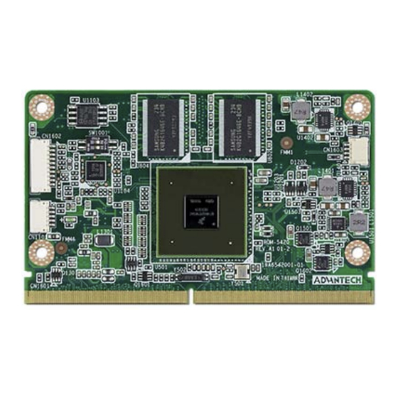
Page 14: Rom-5420 Board Looks
ROM-5420 Board Looks Board Connectors The board has four connectors that allow you to configure your system to your appli- cation. 2.2.1 Connector List External IO Connector Position Description U1103 Flash ROM SW1001 Boot selection CN1602 JTAG connector CN1101 MCU programming port... - Page 15 SD (Reserved for recovery) 2-OFF 2-ON CN1101 (MCU programming port) Signal Signal +3.3 V SWDIO SWCLK MCU_JTAG_RESET CN1602 (JTAG connector) Signal Signal +3.3 V JTAG_TRST# JTAG_TMS JTAG_TDO JTAG_TDI JTAG_TCK JTAG_RTCK CN1603 (Debug connector) Signal Signal +3.3 V UART1_TX UART1_RX ROM-5420 User Manual...
-
Page 16: Rom-5420 Board Block Diagram
ROM-5420 Board Block Diagram Below is the block diagram of ROM-5420. DDR3 eMMC Memory 4GB Flash TTL 24bit LVDS HDMI CSI (Camera input) Ethernet Transceiver RGMII USB Host/OTG PCIe x1 Freescale i.MX6 SATA Dual/Quad SDIO 4 SPI ISC Switch 4 I2C (Slave) -
Page 17: Chapter 3 Software Functionality
Chapter Software Functionality This chapter details the software programs on the ROM-5420 plat- form. -
Page 18: Test Tools
01887800 30 31 32 33 34 35 36 37 38 39 41 42 43 44 45 46 |0123456789ABCDEF| 3.1.3 USB Test Step 1: Insert USB flash disk then assure it is in ROM-5420 device list Step 2: Erase and check #dd if=/dev/sdb of=/dev/sdb bs=1024 count=1 seek=25118... -
Page 19: Sd Test
#echo -n "0123456789ABCDEF" | dd of=/dev/mmcblk1 bs=1024 count=1 seek=25118 0+1 records in 0+1 records out #hexdump -C /dev/mmcblk0 -s 25720832 -n 16 01887800 30 31 32 33 34 35 36 37 38 39 41 42 43 44 45 46 |0123456789ABCDEF| ROM-5420 User Manual... -
Page 20: Gpio Test
GPIO11 gpio177 * GPIO1 & GPIO3 has been reserved for camera input in ROM-5420. You can use the two GPIO ports if you do not need the camera feature. #cd /sys/class/gpio You can use “ls” to list all GPIO devices, and you should also see GPIO ports in above table. -
Page 21: Lvds/Hdmi/Vga Test
You can see display independent both show Advantech.avi at the same time. If you’d like to set the output audio as HDMI out or speaker out, please add the parameter of plughw: A. Plughw:0 → Output the audio through audio jack (AUDIO1) -
Page 22: I2C Test
HDMI video17 HDMI overlay video18 video19 VGA overlay video20 LVDS 0 video21 LVDS 1 3.1.7 I2C Test There are three i2c bus in ROM-5420. #ls /sys/class/i2c-dev i2c-0 i2c-1 i2c-2 i2c-3 i2c-4 i2c-5 i2c-6 #i2cdetect -l i2c-0 imx-i2c I2C adapter... - Page 23 XXXXXXXXXXXXXXXX e0: XX XX XX XX XX XX XX XX XX XX XX XX XX XX XX XX XXXXXXXXXXXXXXXX f0: XX XX XX XX XX XX XX XX XX XX XX XX XX XX XX XX XXXXXXXXXXXXXXXX ROM-5420 User Manual...
-
Page 24: Mini Pcie (Wifi) Test
[6] 12 34 12 34 12 34 3.1.10 Audio Out and MIC In Test MIC IN command is as follows: #arecord -t wav -c 1 -r 44100 -d 5 2.wav Audio out command is as follows: #aplay 2.wav ROM-5420 User Manual... -
Page 25: Opengl Test
3.1.11 OpenGL Test Please follow below instructions to test OpenGL on ROM-5420 platform: Step 1: Change path to /opt/viv_samples/vdk #cd /opt/viv_samples/vdk #ls tutorial* tutorial1 tutorial2_es20 tutorial4 tutorial5_es20 tutorial1_es20 tutorial3 tutorial4_es20 tutorial6 tutorial2 tutorial3_es20 tutorial5 tutorial7 Step 2: Run tutorial7 for OpenGL ES 1.1 Using Vertex Buffer Objects (VBO) can substantially increase performance by reduc- ing the bandwidth required to transmit geometry data. -
Page 26: Rs232 Test
= 0.203/2.640/7.417 ms 3.1.13 RS232 Test As you can see below, there are 5 UART supported by ROM-5420. /dev/ttymxc0 is reserved for ROM-5420 debug port (ROM-5420 CN1), the rest UART ports could be applied by user. #setserial -g /dev/ttymxc*... -
Page 27: Watchdog Timer Test
The actual timeout was set to 10 seconds Now reading back -- The timeout is 10 seconds Press [CTRL+C] then you should be able to see below result: imx2-wdt imx2-wdt.0: Unexpected close: Expect reboot! Then system will reboot in 10 seconds ROM-5420 User Manual... -
Page 28: Audio Test
3.1.15 Audio Test Execute the following commands to run the Audio demo application on ROM-5420. #cd /unit_tests #aplay audio8k16S.wav Then you can hear the music from speaker/head-sets. 3.1.16 Photo Demo Test Execute the following commands to run the Photo demo application on ROM-5420. -
Page 29: Battery Test
# RAWDATA=`i2cget -f -y 4 0x30 0x80 w` # echo $((RAWDATA % 256 * 256 + RAWDATA / 256))mV ROM-5420 platform is an embedded system with Linux kernel 3.0.35 inside. It con- tains all system-required shell commands and drivers ready for ROM-5420 platform. -
Page 30: Package Content
Package Content We would offer you two different kinds of Linux package for ROM-5420. One is pre- built system image for system recovery another is source code package (BSP). 3.2.1 Source Code Package ROM-5420 source code package (BSP) contains cross compiler, Linux source code, Uboot source code, root file system and some scripts used in OS development. - Page 31 → just for sample test. 3.2.1.5 scripts Some scripts provided by Advantech will help you configure system or build the images more quickly. Please check them as follows: – setenv.sh → A script to setup the developing environment quickly.
- Page 32 Linux-specific and general UNIX questions. There are also various README files in ./source/linux-3.0.35/Documentation, you can find the kernel-specified installations and notes for drivers. You can refer to ./ source/linux-3.0.35/Documentation/00-INDEX for a list of the purpose of each README/note. ROM-5420 User Manual...
-
Page 33: Set Up Build Environment
All instructions in this guide are based on Ubuntu 10.04 LTS developing environment. Please install the Ubuntu 10.04 LTS at your PC/NB in advance. When you obtain the ROM-5420 Linux source code package, please refer to follow- ing instructions to extract to your developing environment: Copy "5420LBVxxxx.tar.bz2"... -
Page 34: Build Instructions
This section will guide you how to build the u-boot & Linux kernel. 3.4.1 Build u-boot Image Advantech has written a script to build the u-boot quickly. You can build u-boot image by follow below steps: Open "Terminal" on Ubuntu 10.04 LTS $sudo su (Change to “root”... -
Page 35: Source Code Modification
$sudo su (Change to “root” authority) Input user password. Change directory to BSP's scripts folder #. setenv.sh (To configure the developing environment automatically) #./cfg_kernel.sh menuconfig Then you will see a GUI screen (Linux Kernel Configuration) as below: Figure 3.1 Linux Kernel Configuration ROM-5420 User Manual... - Page 36 Please refer to former Chapter 3.5.1 to rebuild the kernel with RTC driver (Seiko Instruments S-35390A) after completing above steps Note! If you cannot find the driver for your device from the list, please contact your hardware vender. ROM-5420 User Manual...
-
Page 37: Change Rom-5420 Boot Logo
Change directory to BSP's scripts folder #./mksd-linux.sh /dev/sdf Type “y” (Start to copy files, wait until it shows [Done]) Then insert the Linux system SD card to ROM-5420 SD card slot (SD1), it will boot up with Linux environment. 3.6.2... -
Page 38: Boot From Sata
On ROM-5420 platform, type #cd /mk_inand On ROM-5420 platform, type #./mksd-linux.sh /dev/sda (Check the SATA location like: /dev/sda) On ROM-5420 platform, type “y “(Start to copy files, waiting a few minutes until it shows [Done]) Power off and remove this SD card. -
Page 39: Watchdog Timer Sample Code
Insert the Linux system SD card to your developing computer. #cp helloworld /media/rootfs/tool (/media/rootfs is the mounted point of your Linux system SD card) Remove this SD card and insert it to ROM-5420, then open serial console. On ROM-5420 platform, type #root (Login) On ROM-5420 platform, type #cd /tool On ROM-5420 platform, type #./helloworld... - Page 40 If you would like to change the WDT time, please modify: ioctl(fd, WDIOC_SETTIMEOUT, &timeout). ROM-5420 User Manual...
-
Page 41: Gpio Setting
If the panel has problem to be activated, you may need to check the panel datasheet to configure the panel related parameters. The LVDS video mode database is stored in linux-3.0.35/drivers/video/mxc/ldb.c. You can add a new one for your LVDS panel. static struct fb_videomode ldb_modedb[] = { "LDB-XGA", 60, 1024, 768, 15385, ROM-5420 User Manual... - Page 42 Single Display Settings HDMI out, please set in u-boot as below: setenv bootargs_mmc 'setenv bootargs ${bootargs} root=/dev/ mmcblk1p1 rootwait rw video=mxcfb0:dev=hdmi,1920x1080M@60,if=RGB24' VGA out, please set in u-boot as below: setenv bootargs_mmc 'setenv bootargs ${bootargs} root=/dev/ mmcblk1p1 rootwait rw video=mxcfb0:dev=lcd,1920x1080M@60,if=RGB24' ROM-5420 User Manual...
-
Page 43: Network Setup
SYNOPSIS ifconfig [-v] [-a] [-s] [interface] ifconfig [-v] interface [aftype] options | address ... OPTIONS display all interfaces which are currently available, even if down display a short list (like netstat -i) ROM-5420 User Manual... -
Page 44: Storage (Sata /Emmc/Sd Card)
Otherwise, set (or clear) the IFF_BROADCAST flag for the interface. del addr/prefixlen Remove an IPv6 address from an interface. 3.8.7 Storage (SATA /eMMC/SD Card) The storages devices are named as follows: Device Name SATA /dev/sda eMMC /dev/mmcblk0 SD card /dev/mmcblk1 ROM-5420 User Manual... -
Page 45: System Recovery
Chapter System Recovery This chapter introduces how to recover Linux operating system if it is damaged accidentally. -
Page 46: System Recovery
Connect console cable to debug port (CN1) and open serial console program on Ubuntu 10.04 LTS, set baudrate to 115200. For detail console setting, please refer to section 3.6. On ROM-5420 platform, type #root (Login) On ROM-5420 platform, type #cd /mk_inand On ROM-5420 platform, type #./mkinand-linux.sh /dev/mmcblk0 On ROM-5420 platform, type “y “... -
Page 47: Advantech Services
Chapter Advantech Services This chapter introduces Advantech design in serviceability, technical support and warranty policy for ROM-5420 evaluation kit. -
Page 48: Risc Design-In Services
Easy Development Advantech has support firmware, root file-system, BSP or other develop tools for cus- tomers. It helps customers to easy develop their carrier board and differentiate their embedded products and applications. - Page 49 Advantech has been involved in the industrial computer industry for many years and found that customers usually have the following questions when implementing modu- lar designs.
- Page 50 RISC COM. Design stage When a product moves into the design stage, Advantech will supply a design guide of the carrier board for reference. The carrier board design guide provides pin defini- tions of the COM connector with limitations and recommendations for carrier board design, so customers can have a clear guideline to follow during their carrier board development.
-
Page 51: Contact Information
RISC platforms usually have less support for ready-made drivers on the carrier board, therefore the customer has to learn from trial and error and finally get the best solution with the least effort. Advantech’s team has years of experience in customer support and HW/SW development knowledge. Consequently, we can support customers with professional advice and information as well as shortening development time and enabling more effective product integration. -
Page 52: Technical Support And Assistance
Technical Support and Assistance For more information about this and other Advantech products, please visit our web- site at: http://www.advantech.com/ http://www.advantech.com/ePlatform/ For technical support and service, please visit our support website at: <http://support.advantech.com.tw/support/> Visit the Advantech web site at www.advantech.com/support where you can find the latest information about the product. - Page 53 ROM-5420 User Manual...
- Page 54 No part of this publication may be reproduced in any form or by any means, electronic, photocopying, recording or otherwise, without prior written permis- sion of the publisher. All brand and product names are trademarks or registered trademarks of their respective companies. © Advantech Co., Ltd. 2014...
Need help?
Do you have a question about the ROM-5420 and is the answer not in the manual?
Questions and answers