
Subscribe to Our Youtube Channel
Related Manuals for Advantech UNO-2484G


Summary of Contents for Advantech UNO-2484G
- Page 1 User Manual UNO-2484G 電腦 ® Intel Core™ i Standard-Size Automation Computer with 4 x GbE, 1 x mPCIe, 1 x HDMI, 1 x DP, 4 x USB 3.0, and 4 x COM...
- Page 2 限用物質含有情況標示聲明書 Declaration of the Presence Condition of Restricted Substances Marking 設備名稱:電腦 型號 ( 型式 ):UNO-2484G Equipment name Type Designation (Type) 限用物質及其化學符號 Restricted Substances and Their Chemical Symbols 單元 六價鉻 鉛 汞 鎘 多溴聯苯 多溴二苯醚 Unit Hexavalent Lead Mercury Cadmium Polybrominated...
- Page 3 No part of this manual may be reproduced, copied, translated, or transmitted in any form or by any means without the prior written permission of Advantech Co., Ltd. The information provided in this manual is intended to be accurate and reliable.
- Page 4 UNO2484G75312302-T UNO2484G75312401-T UNO2484G75312402-T UNO2484G75312501-T UNO2484G75312502-T UNO2484G75312601-T UNO2484G7731801E-T UNO2484G7731901E-T UNO2484G77312201-T UNO2484G77312202-T UNO2484G77312301-T UNO2484G77312302-T UNO2484G77312401-T UNO2484G77312402-T UNO2484G77312501-T UNO2484G7C212201-T UNO2484G7C212301-T UNO2484G7C212401-T UNO2484G7C212501-T UNO2484G63321701-T UNO2484G63322201-T UNO2484G63322202-T UNO2484G63322203-T UNO2484G63322301-T UNO2484G63322302-T UNO2484G63322303-T UNO2484G63322401-T UNO2484G63322402-T UNO2484G63322403-T UNO2484G63322501-T UNO2484G63322502-T UNO2484G63322503-T UNO2484G63322601-T UNO2484G63322602-T UNO2484G65322201-T UNO2484G65322202-T UNO2484G65322203-T UNO-2484G User Manual...
- Page 5 UNO2484G7532101E-T UNO2484G7532102E-T UNO2484G75322201-T UNO2484G75322202-T UNO2484G75322203-T UNO2484G75322301-T UNO2484G75322302-T UNO2484G75322303-T UNO2484G75322401-T UNO2484G75322402-T UNO2484G75322403-T UNO2484G75322501-T UNO2484G75322502-T UNO2484G75322601-T UNO2484G7732001E-T UNO2484G7732101E-T UNO2484G77322201-T UNO2484G77322202-T UNO2484G77322203-T UNO2484G77322301-T UNO2484G77322302-T UNO2484G77322303-T UNO2484G77322401-T UNO2484G77322402-T UNO2484G77322403-T UNO2484G77322501-T UNO2484G77322502-T UNO2484G77322601-T UNO2484G7C22101E-T UNO2484G7C222201-T UNO2484G7C222202-T UNO2484G7C222301,-T UNO2484G7C222302-T UNO2484G7C222401-T UNO2484G7C222402-T UNO2484G7C222501-T UNO2484G7C222601-T UNO-2484G User Manual...
- Page 6 Product Warranty (2 years) Advantech warrants the original purchaser that each of its products will be free from defects in materials and workmanship for two years from the date of purchase. This warranty does not apply to any products that have been repaired or altered by persons other than repair personnel authorized by Advantech, or products that have been subject to misuse, abuse, accident, or improper installation.
- Page 7 This product has passed the CE test for environmental specifications when shielded cables are used for external wiring. We recommend the use of shielded cables. This type of cable is available from Advantech. Please contact your local supplier for ordering information.
- Page 8 Danger d'explosion si la batterie est mal remplace. Remplacer uniquement par le meme type ou equivalent recommandé par le fabricant. Jeter les piles usagées selon les instructions du fabricant. UNO-2484G User Manual viii...
- Page 9 In accordance with IEC 704-1:1982 specifications, the sound pressure level at the operator’s position should not exceed 70 dB (A). DISCLAIMER: These instructions are provided according to IEC 704-1 standards. Advantech disclaims all responsibility for the accuracy of any statements contained herein. 安全指示...
- Page 10 UNO-2484G User Manual...
-
Page 11: Table Of Contents
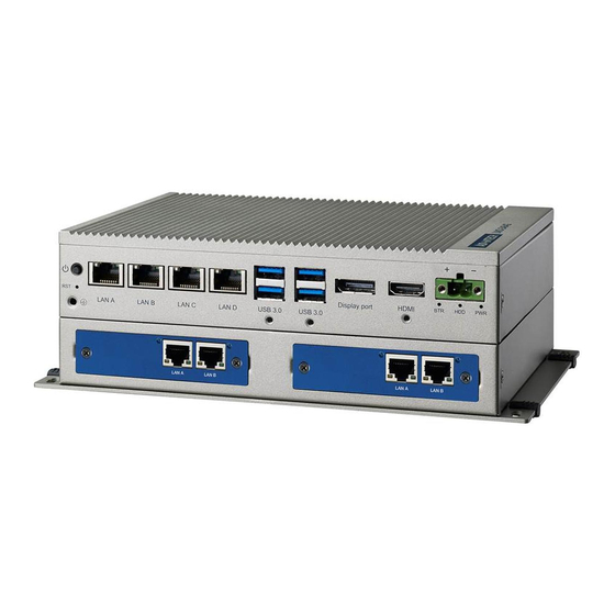
Chapter Hardware Functionality.......5 Introduction ....................6 Figure 2.1 Front panel of the UNO-2484G single-stack model..6 Figure 2.2 Front panel of the UNO2484G dual-stack model ..6 UNO-2484G Interface ................6 2.2.1 COM Port Interface (COM1, COM2, COM3, COM4) ....6 LAN: Ethernet Connector ................ - Page 12 A.10 Screw Type and Quantity for Mounting Module........33 A.11 Modifying the Serial Port Mode............... 34 A.12 Set Bias Resistors and Termination Resistors by Hardware Switches ... 36 A.13 BIOS Settings of TPM 2.0 (Optional) ............40 UNO-2484G User Manual...
-
Page 13: Chapter 1 Overview
Chapter Overview This chapter provides an overview of UNO-2484G specifications. Introduction Safety Precautions Accessories... -
Page 14: Introduction
Equipped with the latest Intel Core™ i pro- cessor, 8 GB of DDR4 RAM, four GbE LAN, and four USB 3.0 ports, UNO-2484G supports one DP and one HDMI display as well as Advantech’s iDoor modules. -
Page 15: Accessories
– Display: 1 x HDMI, supports 1920 x 1080 @60Hz 24bpp and 1 x DP Because UNO-2484G features a modularized design, Advantech offers both single and double-stack models. Single-stack models: ... - Page 16 UNO-2484G User Manual...
-
Page 17: Chapter 2 Hardware Functionality
Chapter Hardware Functionality This chapter explains how to setup UNO-2484G’s hardware functions, including connecting peripherals and setting switches and indicators. Introduction UNO-2484G Interface LAN/Ethernet Connector Power Connector USB Connector RTC Battery Power Button / Power Manage- ment ... -
Page 18: Introduction
Link (Green LED) and Active (Green LED) sta- tus. Power Connector UNO-2484G is equipped with a phoenix power connector that is compatible with 10 ~ 36 V external power and features reversed wiring protection. This protects the sys- tem from damage caused by reversed wiring of ground and power lines. -
Page 19: Usb Connector
BIOS. Additionally, the provision of four USB ports complies with USB EHCI, Rev. 3.0. (Refer to Appendix A.5 for pin assignments.) RTC Battery UNO-2484G has an RTC battery to ensure that the BIOS and system clock settings are retained even after brief power disconnections. Type: Panasonic BR2032 ... - Page 20 Figure 2.3 First stack motherboard Figure 2.4 Second stack extension board UNO-2484G User Manual...
-
Page 21: Chapter 3 Initial Setup
Chapter Initial Setup This chapter explains the process for initializing UNO-2484G. Chassis Grounding Connect the Power Supply Open/Close the Rear Cover Hard Disk Installation Extension Kit Installation... -
Page 22: Chassis Grounding
Figure 3.1 Chassis grounding connection Connect the Power Supply UNO-2484G is intended to be supplied by a listed power adapter or DC power source rated 10 ~ 36V , 8A, and TMA 60°C. Should you require further assistance, please contact Advantech for additional information. -
Page 23: Open/Close The Rear Cover
The rear cover can be opened in order to install an mPCIe module, mSATA SSD, or HDD, or to adjust the switch settings. Open the Rear Cover Remove the four rubber feet. Remove the two affixing screws of the rear cover. Slide to open the rear cover. UNO-2484G User Manual... - Page 24 Close the Rear Cover: Align the guide pillars between the rear cover and bracket, then slide the rear cover in place and fix in position. Secure the rear cover in place using two screws. Then attach the four rubber feet. UNO-2484G User Manual...
-
Page 25: Hard Disk Installation
Hard Disk Installation 3.4.1 HDD/SSD Installation for Single-Stack UNO-2484G Remove the rear cover. Remove the HDD bracket by unscrewing the four affixing screws on the HDD bracket. Attach the HDD/SSD to the HDD bracket using screws. UNO-2484G User Manual... - Page 26 Slide the HDD/SSD attached to the bracket into the chassis. UNO-2484G User Manual...
-
Page 27: Hdd/Ssd Installation For Double-Stack Uno-2484G
Secure the HDD bracket in place using four screws. Replace the rear cover. 3.4.2 HDD/SSD Installation for Double-Stack UNO-2484G Remove the rear cover. Unscrew the five affixing screws to remove the second stack extension kit. UNO-2484G User Manual... - Page 28 Remove the HDD bracket by unscrewing the four screws on the HDD bracket. Attach the HDD/SSD to the HDD bracket using screws. UNO-2484G User Manual...
- Page 29 Slide the HDD/SSD attached to the bracket into the chassis. UNO-2484G User Manual...
- Page 30 Affix the HDD bracket in place using four screws. Reattach the second stack extension kit using five screws. Replace the rear cover. UNO-2484G User Manual...
-
Page 31: Hdd/Ssd Installation With Uno-2484G-S2Ae Ext. Module
3.4.3 HDD/SSD Installation with UNO-2484G-S2AE Ext. Module Below is the list of components provided with the UNO-2484G-S2AE extension mod- ule. Secure the second stack extension kit rear cover (5-1) in place using the screws provided (1). Lock PCBA Port A (3) and Port B (3) with screws (2). - Page 32 Secure the front cover (5-2) in place using the screws provided (1). Ensure that the HDD A port of the front cover and Port A on the PCBA are located on the same side. UNO-2484G User Manual...
- Page 33 Secure the HDD to the HDD tray (5-3) using the screws located at the internal side of the first stack layer. Insert the HDD with tray into the slot and tighten the thumb screws. UNO-2484G User Manual...
- Page 34 Align the guide pillars between the rear cover and bracket, and then slide the rear cover in place to fix in position. Secure the rear cover in place using the screws provided. Then attach the rub- ber feet. UNO-2484G User Manual...
-
Page 35: Extension Kit (Uno-2484G-Ekae) Installation
Extension Kit (UNO-2484G-EKAE) Installation Remove the rear cover. Attach the second extension kit stack to the first stack. Secure the rear cover in place using the two screws provided. Then attach the four rubber feet. UNO-2484G User Manual... - Page 36 UNO-2484G User Manual...
-
Page 37: Appendix A System Settings / Pin Assignments
Appendix System Settings / Pin Assignments... -
Page 38: Cn10 Internal Gpio Pin Header
Table A.1: CN10 Internal GPIO Pin Header Signal GPIO0 GPIO1 GPIO2 GPIO3 GPIO4 GPIO5 GPIO6 GPIO7 Board Connectors and Jumpers The UNO-2484G board features several connectors and jumpers. The following sec- tions explain how to configure the UNO-2484G hardware settings. UNO-2484G User Manual... - Page 39 Internal power connector; the voltage is the same as that for DCIN CN35 Board-to-board connector AT/ATX mode switch. ON -> ATX mode, OFF -> AT mode Clear COMS switch. Pin 1 -> normal, Pin 3 -> Clear Disable internal COM5~8, Pin (1-2) -> enable, Pin (3-4) -> disable UNO-2484G User Manual...
-
Page 40: Power Connector (Pwr)
Signal Name ML_Lane 0 (p) ML_Lane 0 (n) ML_Lane 1 (p) ML_Lane 1 (n) ML_Lane 2 (p) ML_Lane2 (2) ML_Lane 3 (p) ML_Lane 3 (n) CONFIG1 CONFIG2 AUX CH (p) AUX CH (n) Hot Plug Return DP_PWR UNO-2484G User Manual... -
Page 41: Hdmi Display Connector
TMDS Data2 Shield TMDS Data2- TMDS Data1+ TMDS Data1 Shield TMDS Data1- TMDS Data0+ TMDS Data0 Shield TMDS Data0- TMDS Clock+ TMDS Clock Shield TMDS Clock- Reserved DDC/CEC/HEC Ground +5 V Power (max. 50 mA) Hot Plug Detect UNO-2484G User Manual... -
Page 42: Com1/Com2/Com3/Com4 Rs232/422/485 Connector
COM1/COM2/COM3/COM4 RS232/422/485 Connector RS232 RS422 RS485 UNO-2484G User Manual... -
Page 43: Mini Pcie Slot (Minipcie)
Note 1: +3.3V aux is suspend power; power out to device +3.3V/1.1A. Note 2: +3.3V is core power. Note 3: +1.5V is core power; power out to device +1.5V/0.5A. UNO-2484G User Manual... -
Page 44: Lan Rj45 Connector
1000BASE-T: In MDI and in MDI-X configuration, MDI[2]+/- cor- responds to BI_DC+/- and MDI[3]+/- corresponds to BI_DD+/-. 100BASE-TX: Unused. MDI3+ 10BASE-T: Unused. MDI3- Left LED Right LED 10Link 100Link 1000 Link Active Orange Green Green UNO-2484G User Manual... -
Page 45: Cn15/Cn53 Internal Usb 2.0 Pin Header
CN15/CN53 Internal USB 2.0 Pin Header Table A.7: CN15/CN53 Internal USB 2.0 Pin Header Signal USB1- USB2- USB1+ USB2+ A.10 Screw Type and Quantity for Mounting Module UNO-2484G User Manual... - Page 46 The default setting for the serial ports is RS-232 mode. The setting can be configured to RS-422 or RS-485 modes by following the instructions below. Power on the UNO-2484G device and press "Delete" to enter the BIOS configu- ration menu.
- Page 47 Select the serial port (e.g., select “Serial Port 1 Configuration”). Select “COM1 mode” and choose from “RS232 mode”, “RS422 mode”, or “RS485 mode”. UNO-2484G User Manual...
- Page 48 A.12 Set Bias Resistors and Termination Resistors by Hardware Switches Location of new Dip Switches: Dip switch for COM port: Definitions of settings are as shown below. Setting for “ON” Setting for “OFF” UNO-2484G User Manual...
- Page 49 This dip switch is used to select RS485/422 Bias Resistor. Description COM1 RS232 Mode Bit 1,2 off (default) COM1 Bit 1,2 ON RS422/485 Mode COM2 RS232 Mode Bit 3,4 off (default) COM2 Bit 3,4 ON RS422/485 Mode UNO-2484G User Manual...
- Page 50 “on”. This dip-switch is used to select RS485/422 Bias Resistor. Description COM3 RS232 Mode Bit 1,2 off (default) COM3 Bit 1,2 ON RS422/485 Mode COM4 RS232 Mode Bit 3,4 off (default) COM4 Bit 3,4 ON RS422/485 Mode UNO-2484G User Manual...
- Page 51 This dip switch is used to select Termination Resistor (Rc 120 ohm) for long distance transmission or device matching. Description Default setting Bit1~ 4 OFF COM1 bit 1 COM2 bit 2 COM3 bit 3 COM4 bit 4 UNO-2484G User Manual...
- Page 52 A.13 BIOS Settings of TPM 2.0 (Optional) The UNO-2484G series supports the TPM 2.0 function. This function can be enabled or disabled in the BIOS configuration menu by following the instructions below. Power on the UNO-2484G device and press “Delete” to enter the BIOS configu- ration menu.
- Page 53 Choose “Enabled” or “Disabled” to enable/disable the TPM 2.0 function in the BIOS menu. UNO-2484G User Manual...
- Page 54 No part of this publication may be reproduced in any form or by any means, such as electronically, by photocopying, recording, or otherwise, without prior written permission from the publisher. All brand and product names are trademarks or registered trademarks of their respective companies. © Advantech Co., Ltd. 2022...
- Page 55 Links/Pic.jpg @ 150 dpi 8 Links/Pic01.jpg @ 150 dpi 13, 16 Links/Pic02.jpg @ 150 dpi 13, 16 Links/Pic03.jpg @ 150 dpi 13, 16 Links/Pic04.jpg @ 150 dpi 14, 17 Links/Pic05.jpg @ 150 dpi 14, 17 Links/Pic06.jpg @ 150 dpi 15, 18 UNO-2484G User Manual...
- Page 56 Links/Pic07.jpg @ 150 dpi 15 Links/Pic08.jpg @ 150 dpi 18 Links/reference 15.jpg @ 150 dpi 29 Links/Template_Caution.gif @ 150 dpi 2 Links/Template_EA_FrontCover.ai i Links/Template_Note.png @ 150 dpi 7 Links/Template_Warning.gif @ 150 dpi 2 Links/top.png @ 150 dpi 27 UNO-2484G User Manual...
Need help?
Do you have a question about the UNO-2484G and is the answer not in the manual?
Questions and answers