
Related Manuals for Advantech RSB-4221


Summary of Contents for Advantech RSB-4221
- Page 1 User Manual RSB-4221 RISC 3.5inch SBC based on TI Sitara AM3358 Cortex A8 1Ghz High Performance Processor...
- Page 2 The documentation and the software included with this product are copyrighted 2016 by Advantech Co., Ltd. All rights are reserved. Advantech Co., Ltd. reserves the right to improve the products described in this manual at any time without notice. No part of this manual may be reproduced, copied, translated, or transmitted in any form or by any means without the prior written permission of Advantech Co., Ltd.
- Page 3 Follow these simple precautions to protect yourself from harm and the products from damage. To avoid electrical shock, always disconnect the power from your PC chassis before you work on it. Don't touch any components on the CPU card or other cards while the PC is on. RSB-4221 User Manual...
- Page 4 Packing List Before installation, please ensure the following items have been shipped: 1 x RSB-4221 3.5inch SBC Optional Accessories Part No. Description 96PSA-A36W12R1 Adapter A/D 100-240V 36W 12V 1700023575-01 CAN Cable 1700023576-01 USB Cable 1700023707-01 Debug Cable SQF-ISDS1-4G-82C SQF SD C6 SLC 4G, 1CH...
- Page 5 The equipment has been dropped and damaged. The equipment has obvious signs of breakage. DISCLAIMER: This set of instructions is given according to IEC 704-1. Advantech disclaims all responsibility for the accuracy of any statements contained herein. RSB-4221 User Manual...
- Page 6 RSB-4221 User Manual...
-
Page 7: Table Of Contents
2.4.1 Debug Port Connection............... 24 2.4.2 Debug Port Setting..............24 Figure 2.20Hyper Terminal Settings for Terminal Setup .... 24 Chapter Software Functionality ......25 Test Tools ....................26 eMMC Test....................26 USB Test....................27 SD Test ....................27 RSB-4221 User Manual... - Page 8 Serial Tools................. 53 Figure 4.10Serial Control............53 4.8.8 Matrix GUI User’s Guide............. 54 Figure 4.11Matrix................ 54 4.8.9 Screen rotation for Qt application ..........55 4.8.10 Add a Startup items when boot........... 56 4.8.11 Package online install ..............56 RSB-4221 User Manual viii...
- Page 9 Obtaining an RMA Number............67 5.5.2 Returning the Product for Repair ..........67 5.5.3 Service Charges ................. 68 5.5.4 Repair Report................69 5.5.5 Custody of Products Submitted for Repair........69 5.5.6 Shipping Back to Customer ............69 RSB-4221 User Manual...
- Page 10 RSB-4221 User Manual...
-
Page 11: Chapter 1 General Introduction
Chapter General Introduction This chapter gives background information on the RSB-4221. Sections include: Introduction Specification... -
Page 12: Introduction
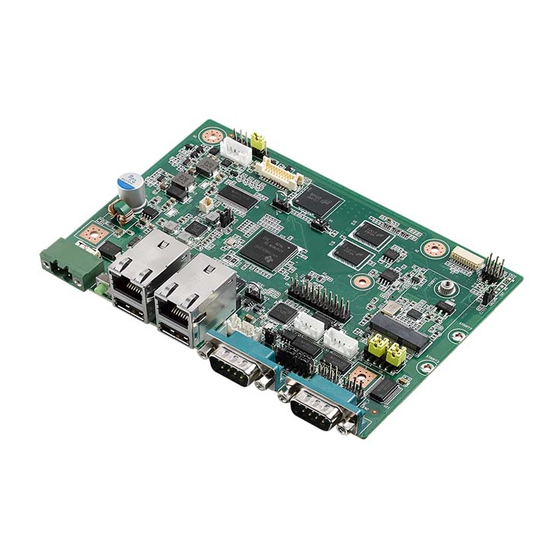
Introduction RSB-4221 is a RISC SBC integrated with a TI Sitara AM3358 Cortex-A8 processor. It is an ideal solution for automation control applications such as smart grids, and industrial and machinery automation due to its ample I/O interface and network func- tionality. -
Page 13: Mechanical Specifications
– Normal discharge capacity: 240 mAh Environmental Specifications Operating temperature: 0~60°C (32~1400~60°F) Operating humidity: 0% ~ 90% relative humidity, non-condensing Storage temperature: -40~85°C (-40~185°F) Storage humidity: 60°C @ 95% RH Non-condensing Block Diagram RSB-4221 User Manual... - Page 14 RSB-4221 User Manual...
-
Page 15: Chapter 2 H/W Installation
Chapter H/W Installation This chapter gives mechanical and connector information on the RSB-4221 3.5 inch SBC. Sections include: Jumper Information Connector Information Mechanical Drawing Quick Start Guide... -
Page 16: Jumpers
2.1.2 Jumper List Table 2.1: Jumper List Boot device select(SW1) LVDS power level select(CN3) Backlight power level select (CN2) COM1 RS232 and RS485 mode detect(CN10) COM1 RS232, RS422, RS485 signal select (JSETCOM1) COM1 switch (CN14) RSB-4221 User Manual... -
Page 17: Jumper Settings
This pin header is designed for selecting LCD power level. Backlight power level select (CN2) Part Number 1653003100 Footprint HD_3x1P_100_D Description PIN HEADER 3x1P 2.54mm 180D(M) DIP 205-1x3GS Setting Function (1-2) (2-3) +V12 This pin header is designed for selecting LCD backlight power level. RSB-4221 User Manual... - Page 18 (5-6 7-9 8-10 13- RS232 mode (CN10must be set RS232 at the same time) 15 14-16) (3-59-11 10-12 15- RS422 mode 17 16-18) (1-2 9-11 10-12 RS485 mode (CN10must be set RS485 at the same time) 15-17 16-18) RSB-4221 User Manual...
-
Page 19: Connectors
CAN CONN CN12 GPIO CONN CN20 USB Type A Connector CN19 USB Type A Connector CN18 USB Pin Box JTAG Connector CN19 Ethernet Connector CN20 Ethernet Connector SD Card LVDS CONN LVDS Backlight CN21 DC-Power Jack Recovery RSB-4221 User Manual... -
Page 20: Connector Settings
2.2.2 Connector Settings 2.2.2.1 RTC Battery Connector (CN9) RSB-4221 supports a lithium 3V/210mAH CR2032 battery with wire via battery con- nector. Figure 2.1 DC RTC Battery Connector 2.2.2.2 M.2 (CN11) RSB-4221 supports socket1 connectivity type 2230 S1&S2&S3 key EM.2 interface. - Page 21 Figure 2.2 M.2 CONNECTOR 2.2.2.3 UART0 debug port (COM0) RSB-4221 can communicate with a host server (Windows or Linux) by using stan- dard DB9. Description COM0_RX COM0_TX RSB-4221 User Manual...
- Page 22 Figure 2.3 COM PORT 2.2.2.4 UART1 COM port (COM1) RSB-4221provides a standard DB9 which can support RS232/RS422/RS485 by changing CN10/ JSETCOM1 jumper. Description COM1_DCD COM1_RX COM1_TX COM1_DTR COM1_RTS COM1_CTS Figure 2.4 COM PORT RSB-4221 User Manual...
- Page 23 2.2.2.5 UART2 and UART3 COM port Pin Connector (COM2_3) RSB-4221 provides a 2x3 pin connector, which contains 2 two-wire COM ports (RS232 level). Description COM2_TX COM3_TX COM2_RX COM3_RX Figure 2.5 COM port pin header 2.2.2.6 UART4 and UART5 COM port Pin Connector (COM4_5) RSB-4221 provides a 2x3 pin connector, which contains 2 two-wire COM ports (RS232 level).
- Page 24 Figure 2.7 CAN port Connector 2.2.2.8 GPIO Pin Connector (CN12) RSB-4221 provides a 10x2 pin connector for GPIO (supports 3.3V level/GPIO_PWR 3.3V) Description GPIO_PWR NO PIN GPIO0 GPIO7 GPIO1 GPIO8 GPIO2 GPIO9 GPIO3 GPIO10 GPIO4 GPIO11 GPIO5 GPIO12 GPIO6 GPIO13 Figure 2.8 GPIO pin header...
- Page 25 Figure 2.9 USB port connector 2.2.2.10 USB Type A Connector (CN19) Description USB_P2L_N USB_P2L_P Figure 2.10 USB port connector 2.2.2.11 USB Pin Box (CN18) RSB-4221supports a pin box header that contains two USB2.0 ports. Description USB_P3L_N USB_P4L_N USB_P3L_P USB_P4L_P RSB-4221 User Manual...
- Page 26 Figure 2.11 USB port connector 2.2.2.12 JTAG (CN1) JTAG connector is used for internal debugging only. Description +3.3V JTAG_TRSTn JTAG_TMS JTAG_TDO JTAG_TDI JTAG_TCK JTAG_EMU0 JTAG_RESETn JTAG_EMU1 Figure 2.12 JTAG Pin header RSB-4221 User Manual...
- Page 27 2.2.2.13 Ethernet Connector (CN19) RSB-4221 provides two RJ45 LAN interface connectors which are compliant with 1000 base-T IEEE 802.ab,100 base-TX IEEE 802.u, 10 base-t IEEE 802.3.The Ethernet ports provide standard RJ-45 jack connector with LED indicators on the front side to show Active/Link status and speed status.
- Page 28 2.2.2.14 Ethernet Connector (CN20) Description MDI10+ MDI10- MDI11+ MDI11- MDI12+ MDI12- MDI13+ MDI13- LAN1_100_LINK LAN1_1000_LINK +3.3V LAN1_ACT Figure 2.14 Ethernet Connector RSB-4221 User Manual...
- Page 29 2.2.2.16 LVDS Connector (CN5) RSB-4221 provides an LVDS 10x2-pin board-to-board connector for single channel 18 bit LVDS panel up to 1366x768. To avoid damaging the LCD panel, please make sure to set the right voltage level before powering on (refer to jumper setting descrip- tion for CN3 and LCD datasheet that you will use).
- Page 30 To avoid damaging the LCD panel, please make sure set the right voltage level before powering on (refer to jumper setting description for CN2 and LCD datasheet that you will use). Description +VDD_BKLT_LVDS LCD_BKLT_A LCD_BKLT_PWM_A Figure 2.17 LVDS Inverter Power Connector RSB-4221 User Manual...
- Page 31 2.2.2.19 Recovery (SW2) RSB-4221 supports a recovery function when it runs on Android OS. Under Linux OS the recovery button (SW2) is useless. You must press SW2 for about 5 seconds as the board powers up. Generally speaking, you can find the following string under...
-
Page 32: Mechanical
Mechanical 2.3.1 Jumper and Connector Location LAN1 LAN2 COM0 COM1 Recovery DC-In USB1 USB2 COM2,3,4,5 USB3,4 GPIO Backlight LVDS SD Slot RSB-4221 User Manual... -
Page 33: Board Dimension
2.3.2 Board Dimension RSB-4221 User Manual... -
Page 34: Quick Start Guide
Figure 2-7. After the bootloader is programmed on the SD card, insert power adapter con- nector to DC jack on RSB-4221 to power up the board. The bootloader prompt is displayed on the terminal screen. Figure 2.20 Hyper Terminal Settings for Terminal Setup... -
Page 35: Chapter 3 Software Functionality
Chapter Software Functionality This chapter details the software programs on the RSB-4221 plat- form. -
Page 36: Test Tools
Test Tools All test tools must be verified on RSB-4221, please prepare required test fixtures before verifying each specified I/O. If you have any problem to get the test fixture, please contact your Advantech contact window for help. eMMC Test... -
Page 37: Usb Test
W95 FAT32 (LBA) /dev/mmcblk0p2 160650 7759394 3799372+ Linux Run program to read/write SD. root@am335x-adv:/unit_tests# ./AutoRun_sd.sh mmcblk0 10240+0 records in 10240+0 records out 10240+0 records in 10240+0 records out 10240+0 records in 10240+0 records out =================SD test pass================ RSB-4221 User Manual... -
Page 38: Spi Test
Copied 4194304 bytes from address 0x00000000 in flash to ./temp-0.img 0000000 0000 0000 0000 0000 0000 0000 0000 0000 0400000 ============================================================== ################## --------------SPI mtdblock0 Write 0 PASS !!! ============================================================== ============================================================== ###################-----------> SPI Test all mtdblock0 PASS !!! RSB-4221 User Manual... -
Page 39: I2C Test
60: -- -- -- -- -- -- -- -- -- -- -- -- -- -- -- -- 70: -- -- -- UU -- -- -- -- =====I2C test Pass!===== CAN Test Connect one RSB-4221 CAN Port CAN1_D+ /CAN1_D- and GND with another RSB-4221. Run program to transmit data between two RSB-4221 CAN ports. root@am335x-adv:/unit_tests# ./AutoRun_CAN.sh... -
Page 40: Gpio Test
GPIO Test Power on RSB-4221 and boot into OS Run program to test GPIO read/write. root@am335x-adv:/unit_tests# ./AutoRun_gpio.sh GPIO200 direction is: GPIO201 direction is: GPIO202 direction is: GPIO203 direction is: GPIO204 direction is: GPIO205 direction is: GPIO206 direction is: GPIO207 direction is:... -
Page 41: Lvds Test
M2WIFIFlag=TRUE" 3.10.1 M.2 wifi Test Connect the marverll WIFI module to M.2 interface under rsb-4221 board, the supported module is sd8897. Run program test_wifi.sh to load drivers. root@am335x-adv:/unit_tests/Marverll_8897_driver# ./test_wifi.sh ************************************************** Begin Set the Wireless ************************************************** [ 107.156327] cfg80211: Calling CRDA to update world regulatory domain... -
Page 42: Bluetooth Test
3.10.2 Bluetooth Test To use Marvel Bluetooth, please according to the following steps: Connect the marverllWIFI module to M.2 interface under rsb-4221 board, the supported module is sd8897. After entering the linux system, insert the module for Bluetooth: root@am335x-adv:~# insmod /unit_tests/Marverll_8897_driver/bt8xxx.ko 28.790453] BT: Loading driver... -
Page 43: Lan Test
LAN Test RSB-4221 sets DHCP as defaul network portocal. 3.11.1 eth0 Test Connect RSB-4221 eth0 port with a host computer. Config RSB-4221 eth0 IP as 192.168.1.2.meanwhile,config the host computer IP as 192.168.1.1 root@am335x-adv:~# ifconfig eth0 192.168.1.2 root@am335x-adv:~# ifconfig eth0 eth0 Link encap:EthernetHWaddr 78:A5:04:DD:E1:0A inet addr:192.168.1.2 Bcast:192.168.1.255 Mask:255.255.255.0... -
Page 44: Serial Port Test
64 bytes from 192.168.1.1: seq=5 ttl=64 time=0.107 ms 3.12 Serial Port Test There are 6 serial port supported by RSB-4221. /dev/ttyO0 is reserved for RSB-4221 debug port (RSB-4221 COM0), the rest UART ports could be applied by user. 3.12.1 COM1~COM5 RS232 Test Switching jumper as described before (please refer to 2.1.2 Jumper List) to switch... -
Page 45: Com1 Rs485 Test
Writing:This is a test for Loopback /dev/ttyO1 Reading : This is a test for Loopback /dev/ttyO1 ->TX/RX Signal pass Close uart /dev/ttyO1 PASS ..Close uart /dev/ttyO4 PASS ..+-----------------------------------+ | UART RS485 Testing PASS | +-----------------------------------+ RSB-4221 User Manual... -
Page 46: Watchdog Timer Test
3.13 Watchdog Timer Test RSB-4221 has an external watchdog IC using TI msp430g2202, which will reset sys- tem when exception occurs. Please refer to the flow diagram below. The valid timeout value for watchdog is from 1 to 6553 seconds, and the default time- out value is 60 seconds. - Page 47 ConfigData=0xde (UTMI-8, dyn FIFOs, bulk combine, bulk split, HB-ISO Rx, HB-ISO Tx, SoftConn) musb-hdrc: MHDRC RTL version 2.0 musb-hdrc: setup fifo_mod RSB-4221 User Manual...
- Page 48 RSB-4221 User Manual...
-
Page 49: Chapter 4 Linuxbsp
Chapter LinuxBSP This chapter introduces how to build an Android system and develop based our Linux system. -
Page 50: Introduction
In this case, we strongly recommend using Ubuntu 12.04 LTS installed on your host PC before starting RSB-4221 evaluation/development. Package Content We offer you two different kinds of Linux package for RSB-4221. One is a pre-built system image for system recovery, another is a source code package (BSP). 4.2.1 Pre-built System Image You can find the pre-built image 4221LIVxxxx_yyyy-mm-dd.tar.gz from RSB-4221... - Page 51 The description of RSB-4221 BSP package contents: “cross_compiler” ->This folder contains source code for cross compiler. “document” ->This folder contains user guide. “image” ->This folder contains the uImage, u-boot.img “image/rootfs” ->This folder contains Linux root file system ...
- Page 52 ->just for sample test. Figure 4.2 image\rootfs 4.2.2.5 Scripts Some scripts provided by Advantech will help you configure system or build the images more quickly. Please check them as follows: setenv.sh ->A script to setup the development environment quickly.
-
Page 53: Set Up Build Environment
All instructions in this guide are based on Ubuntu 12.04 LTS development environ- ment. Please install the Ubuntu 12.04 LTS at your PC/NB in advance. When you obtain the RSB-4221 Linux source code package, please refer to following instructions to extract to your development environment: Copy "335XLBVxxxx_yyyy-mm-dd.bin"... -
Page 54: Setenv.sh
This section will guide you how to build the u-boot & Linux kernel. 4.4.1 Build u-boot Image Advantech has written a script to build the u-boot quickly. You can build u-boot image by follow below steps: Open "Terminal" on Ubuntu 12.04 LTS.. -
Page 55: Kernel Source Code Modification
(Change to “root” authority) $sudo su Input user password. #cd /root/335XLBVxxxx_yyyy-mm-dd/scripts/ (To configure the development environment automatically) #. setenv.sh #./cfg_kernel.sh am335x_rsb4221_defconfig# ./cfg_kernel.sh menuconfig Then you will see a GUI screen (Linux Kernel Configuration) as below: Figure 4.3 Linux Kernel Configuration RSB-4221 User Manual... - Page 56 S-35390A” on the list. Choose this option then exit and save your config- uration. Figure 4.4 Selecting Seiko Instruments S-35390A Change directory to “source/ linux-3.2.0-psp04.06.00.11/arch/arm/mach- omap2”, edit the“board-rsb4221.h” and “board-advantech.c”. Please add below codes to source/ linux-3.2.0-psp04.06.00.11/arch/arm/mach- mx6/board-rsb4221.h: /* I2C */...
-
Page 57: Create A Linux System Boot Media
Check the SD card location, like: /dev/sdb #cd /root/335XLBVxxxx_yyyy-mm-dd/scripts #./mksd-linux.sh /dev/sdb Type “y” (Start to copy files, wait until it shows [Done]) Insert the Linux system SD card into the RSB-4221 SD card slot (SD1) to boot up your Linux environment. RSB-4221 User Manual... -
Page 58: Boot From Onboard Flash
You can then boot from the onboard flash without an SD card. Debug Message RSB-4221 can connect to a host PC (Linux or Windows) by using console cable and debug port adapter. In order to communicate with host PC, a serial communication program such as HyperTerminal, Tera Term or PuTTY is required. -
Page 59: Linux System Configuration And Use
/tftpboot. You need to execute “chmod 777 /tftpboot” on RSB-4221 to let the tftp server work. Then, users can tftp to RSB-4221 via the tftp cli- ent on host PC. Use this command to get and put files: hostPC$ tftp TARGET_SYSTEM_IP tftp>get file1... -
Page 60: Network Configuration
Then you can ftp the RSB-4221 using user ftp. 4.8.2.3 sshserver When booting up the RSB-4221, the ssh service is already started by default. You can run the following command on your host PC to login to RSB-4221: hostPC$ sudossh-l root TARGET_SYSTEM_IP The service start command is: root@am335x-adv:/ # /etc/init.d/dropbear start... - Page 61 'nameserver 172.21.128.251' >> /etc/resolv.conf If you want to reserve the setting after rebooting the device, set as below advantech# echo "/sbin/ifconfig eth0 172.21.73.191 netmask 255.255.255.0; / sbin/route add default gw 172.21.73.253 eth0;echo 'nameserver 172.21.128.251' > /etc/resolv.conf;" > /etc/adv.d/netcfg.eth0 advantech# echo "/sbin/ifconfig eth1 192.168.3.102 netmask 255.255.255.0;...
-
Page 62: Date/Time Configuration
Date/Time Configuration* You can use the tool we provide to modify the system time. Click on the "Time Set- tings" icon on the screen. Then Advantech Date/Time Settings utility will be started. Figure 4.7 Date/Time Settings After the time is adjusted, please click “OK” button, and the date will be saved. Mean- while, the RTC time will be synchronized to the time you just set. -
Page 63: Brightness Control
We provide a GUI application to control the brightness. So, you can conveniently adjust the screen brightness. Figure 4.9 Brightness Control 4.8.7 Serial Tools We have five serial ports, named ttyO1~ttyO5. We provide a serial test tool to easily validate the serial ports. Figure 4.10 Serial Control RSB-4221 User Manual... -
Page 64: Matrix Gui User's Guide
Matrix comes as a 6x4 matrix of icons or as a 4x3 matrix depend- ing on the display resolution. The launcher for Matrix is just a simple QT application that displays a Webkit based browser that points to the URL http://localhost:80. Figure 4.11 Matrix RSB-4221 User Manual... -
Page 65: Screen Rotation For Qt Application
/etc/init.d/matrix-gui-2.0 start If you want the Matrix to start with the system by default, please run the following command on RSB-4221: advantech# cp /etc/init.d/matrix-gui-2.0 /etc/rc5.d/S97matrix-gui-2.0 When you want to cancel the default startup, just remove the S97matrix-gui-2.0 file. -
Page 66: Package Online Install
It is intended for use on embedded Linux devices and is used in this capacity in the OpenEmbedded and OpenWrt projects. Advantech Embedded Linux for RSB-4221 has built-in OPKG package manager, with this tool you can install most of the required software online and manage them such as uninstall, upgrades and so on. -
Page 67: Development Guide And Reference
Development of GUI Programs with QT Library With the development kit, you can develop a qt-based GUI program. Follow these steps, you can quickly convert your QT Project to a GUI application for RSB-4221: On your host PC, set up QT Build Environment... -
Page 68: Demo Program Source Code
4.9.3.2 Watchdog Programming RSB-4221 support hardware watchdog, the watchdog API follows posix standards. The valid timeout value is from 1 to 6553 seconds, if the timeout value set is not in this scope, the driver will set timeout value to default value (60 seconds). - Page 69 = 0; ioctl (fd, WDIOC_GETTIMEOUT, &timeout); Please refer to <BSP_PATH>/source/demo/watchdogfolderto get more information. 4.9.3.3 Gpio Programming RSB-4221 has 8 gpios. Please refer to <BSP_PATH>/source/demo/gpio Usage: # ./gpio 200 out 1 Note. “200” means gpio0, and so 200-207 corresponds to gpio0-gpio7 “out”...
- Page 70 /sys/class/backlight/pwm-backlight/brightness You can set brightness using the following command: #echo "20" > /sys/class/backlight/pwm-backlight/brightness Note. The value should be between 1-100. You can get the current brightness values using the following command: #cat /sys/class/backlight/pwm-backlight/brightness RSB-4221 User Manual...
-
Page 71: Chapter 5 Advantech Services
Chapter Advantech Services This chapter introduces Advan- tech design in serviceability, tech- nical support and warranty policy for RSB-4221 evaluation kit. -
Page 72: Risc Design-In Services
Easy Development Advantech has support firmware, root file-system, BSP or other develop tools for cus- tomers to help them easily develop their carrier board and differentiate their embed- ded products and applications. - Page 73 Advantech has been involved in the industrial computer industry for many years and found that customers usually have the following questions when implementing modu- lar designs.
- Page 74 RISC COM. Design stage When a product moves into the design stage, Advantech will supply a design guide of the carrier board for reference. The carrier board design guide provides pin defini- tions of the COM connector with limitations and recommendations for carrier board design, so customers can have a clear guideline to follow during their carrier board development.
-
Page 75: Contact Information
RISC platforms usually have less support for ready-made drivers on the carrier board, therefore the customer has to learn from trial and error and finally get the best solution with the least effort. Advantech’s team has years of experience in customer support and HW/SW development knowledge. Consequently, we can support customers with professional advice and information which shortens develop- ment time and allows effective product integration. -
Page 76: Technical Support And Assistance
(Dead-on-Arrival). The DOA Cross-Shipment excludes any shipping damage, cus- tomized and/or build-to-order products. For those products which are not DOA, the return fee to an authorized ADVANTECH repair facility will be at the customers' expense. The shipping fee for reconstructive products from ADVANTECH back to customers' sites will be at ADVANTECH's expense. -
Page 77: Exclusions From Warranty
"Problem Description". Vague entries such as "does not work" and "failure" are not acceptable. If you are uncertain about the cause of the problem, please contact ADVANTECH's Application Engineers (AE). They may be able to find a solution that does not require sending the product for repair. -
Page 78: Service Charges
Product updates and tests upon the request of customers who are without war- ranty. If a product has been repaired by ADVANTECH, and within three months after such a repair the product requires another repair for the same problem, ADVANTECH will do this repair free of charge. -
Page 79: Repair Report
5.5.5 Custody of Products Submitted for Repair ADVANTECH will retain custody of a product submitted for repair for one month while it is waiting for return of a signed P/I or payment (A/R). If the customer fails to respond within such period, ADVANTECH will close the case automatically. ADVAN- TECH will take reasonable measures to stay in proper contact with the customer dur- ing this one month period. - Page 80 No part of this publication may be reproduced in any form or by any means, such as electronically, by photocopying, recording, or otherwise, without prior written permission from the publisher. All brand and product names are trademarks or registered trademarks of their respective companies. © Advantech Co., Ltd. 2016...
Need help?
Do you have a question about the RSB-4221 and is the answer not in the manual?
Questions and answers