Table of Contents
Advertisement
Quick Links
Advertisement
Table of Contents

Subscribe to Our Youtube Channel
Related Manuals for Advantech AiMC-2000


Summary of Contents for Advantech AiMC-2000
- Page 1 User Manual AiMC-2000 Fanless Embedded Micro Computer...
- Page 2 Attention! This package contains a hard-copy user manual in Chinese for China CCC certification. Please disregard the printed Chinese copy of the user manual if the product is not to be sold and/or installed in China. AiMC-2000 User Manual...
- Page 3 No part of this manual may be reproduced, copied, translated or transmitted in any form or by any means without the prior written permission of Advantech Co., Ltd. Information provided in this manual is intended to be accurate and reliable. How- ever, Advantech Co., Ltd.
- Page 4 Because of Advantech’s high quality-control standards and rigorous testing, most of our customers never need to use our repair service. If an Advantech product is defec- tive, it will be repaired or replaced at no charge during the warranty period. For out- of-warranty repairs, you will be billed according to the cost of replacement materials, service time and freight.
- Page 5 Technical Support and Assistance Visit the Advantech web site at www.advantech.com/support where you can find the latest information about the product. Contact your distributor, sales representative, or Advantech's customer service center for technical support if you need additional assistance. Please have the following information ready before you call: –...
- Page 6 Discard used batteries according to the manufacturers instructions. ATTENTION: L'ordinateur est muni d'un circuit en temps réel de l'horloge ali- mentée par batterie. Il ya un danger d'explosion si la pile est remplacée de AiMC-2000 User Manual...
- Page 7 Remplacez uniquement par un type identique ou équivalent vii AiMC-2000 User Manual recommandé par le fabricant. Jetez les piles usag CAUTION: Always completely disconnect the power cord from your chassis whenever you work with the hardware. Do not make connections while the power is on.
- Page 8 AiMC-2000 User Manual viii...
-
Page 9: Table Of Contents
Ethernet ..................3 1.3.4 Power Requirement ..............3 Environmental Specifications ..............3 Mechanical Specifications................. 4 1.5.1 AiMC-2000 Dimensions ..............4 Figure 1.1 AiMC-2000 mechanical dimension drawing ....4 Chapter General Information ......5 Jumpers ....................6 2.1.1 Jumper Options................6 2.1.2 Setting Jumper on main board............ - Page 10 Appendix A Programming the Watchdog Timer . 39 Programming the Watchdog Timer ............40 A.1.1 Watchdog Timer Overview ............40 A.1.2 Programming the Watchdog Timer..........40 Table A.1: Watchdog Timer Registers........42 A.1.3 Example Program ............... 43 AiMC-2000 User Manual...
-
Page 11: Chapter 1 General Introduction
Chapter General Introduction This chapter gives background information on AiMC-2000. -
Page 12: Introduction
150% and the graphic performance offers significant improve- ment. AiMC-2000 not only provides dual display, VGA and HDMI port, six COM ports, eight USB ports including one USB 3.0, dual LAN ports, but also provides dual stor- age, mSATA and a hard drive of 2.5 inch HDD for massive data storage. -
Page 13: Display
Vibration loading during operation: With HDD: 0.5 Grms, IEC 60068-2-64, random, 5 ~ 500 Hz, 1 hr/axis Shock during operation: With HDD: 10 G, IEC 60068-2-27, half sine, 11 ms duration Safety: UL,CB,CCC EMC: CE, FCC Class A, CCC AiMC-2000 User Manual... -
Page 14: Mechanical Specifications
Mechanical Specifications 1.5.1 AiMC-2000 Dimensions Unit:mm Figure 1.1 AiMC-2000 mechanical dimension drawing AiMC-2000 User Manual... -
Page 15: Chapter 2 General Information
Chapter General Information... -
Page 16: Jumpers
Pins 2 and 3 as closed for a few seconds before moving the jumper back to Pins 1 and 2 as closed. This procedure resets the CMOS to its default settings. Table 2.1: CMOS Mode Selection (JRTCTEST1) Function Setting Normal (Default) Clear CMOS AiMC-2000 User Manual... -
Page 17: Com1 Rs-232/422/485 Mode Selector (Jsetcom1)
Function Jumper Settings RS-232* (5-6) + (7-9) + (8-10) + (13-15) + (14-16) closed RS-422 (3-4) + (9-11) + (10-12) + (15-17) + (16-18) closed RS-485 (1-2) + (9-11) + (10-12) + (15-17) + (16-18) closed *default AiMC-2000 User Manual... -
Page 18: Rs-485/422 Terminal Resistor Jumper (Sw_422_1)
Table 2.5: JOBS1 + JWDT1: OBS Beep and Watchdog Timer Output Closed Pins Result 2-3* Watchdog reset 4-5* OBS alarm default Function Settings Watchdog Timer Output (2-3) (default) OBS BEEP (4-5) (default) Watchdog Timer disabled (1-2) OBS BEEP (4-5) (default) AiMC-2000 User Manual... -
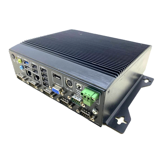
Page 19: Aimc-2000 I/O Indication
AiMC-2000 I/O Indication 2.2.1 Front I/O Indication Remote USB2.0 USB3.0 PS/2 Power Line out USB2.0 USB2.0 HDMI KB/MS On/Off Line in LAN2 LAN1 4*USB2.0 DC in HDD LED Power Switch RS-232/422/485 (COM1) RS-232(4) RS-232(5) RS-232(6) RS-232(2) RS-232(3) I/O Connectors 2.3.1... -
Page 20: Ps/2 Keyboard And Ps/2 Mouse Connector (Kbms1)
Mouse DATA Keyboard CLK Mouse CLK 2.3.4 VGA connector (VGA1) Signal Signal GREEN BLUE RED GND GREEN GND BLUE GND SGND HSYNC VSYNC 2.3.5 RJ45+USB2.0 x2 stack connector (LAN2_USB34) Signal Signal MDI_0+ MDI_0- MDI_1+ MDI_1- MDI_2+ MDI_2- AiMC-2000 User Manual... -
Page 21: Rj45+Usb2.0+Usb3.0 Stack Connector (Lan1_Usb12)
USB_D3+ 2.3.6 RJ45+USB2.0+USB3.0 stack connector (LAN1_USB12) Signal Signal MDI_0+ MDI_0- MDI_1+ MDI_1- MDI_2+ MDI_2- MDI_3+ MDI_3- +5V_USB USB_D1- USB_D1+ +5V_USB USB_D0- USB_D0+ USB3_RX0- USB3_RX0+ USB3_TX0- USB3_TX0+ 2.3.7 HD Analog Audio Interface (AUDIO1) Signal LINE IN LINE OUT AiMC-2000 User Manual... -
Page 22: Usb2.0 X4 Stack Connector (Usb5678)
2.3.8 USB2.0 x4 stack connector (USB5678) Signal Signal +5V_USB USB_D6- USB_D6+ +5V_USB USB_D5- USB_D5+ +5V_USB USB_D7- USB_D7+ +5V_USB USB_D8- USB_D8+ 2.3.9 COM1 connector (COM1) RS-232 RS-422 RS-485 Signal DCD# DATA- DATA+ DTR# DSR# RTS# CTS# AiMC-2000 User Manual... -
Page 23: Remote Power On/Off Connector
2.3.10 Remote Power on/off connector Signal Power Button AiMC-2000 User Manual... -
Page 24: Installation
Installation 2.4.1 Memory/mSATA/mini PCIe Device Installation Remove bottom cover and HDD tray. AiMC-2000 User Manual... - Page 25 Install memory/mSATA/mini PCIe device. Install mini PCIe Install mSATA Install memory Install memory Install bottom cover and HDD tray. AiMC-2000 User Manual...
-
Page 26: Hdd Installation
2.4.2 2.5” HDD Installation Remove bottom cover and HDD tray. AiMC-2000 User Manual... - Page 27 Install HDD to HDD tray. Install bottom cover and HDD tray. AiMC-2000 User Manual...
- Page 28 AiMC-2000 User Manual...
-
Page 29: Chapter 3 Bios Operation
Chapter BIOS Operation... -
Page 30: Introduction
AiMC-2000 BIOS setup menu pages. BIOS Setup The AiMC-2000 is equipped with built-in AMI BIOS and a CMOS Setup Utility that allows users to configure specific settings or activate certain system features. The CMOS Setup Utility saves the configuration in the CMOS RAM of the mother- board. -
Page 31: Main Menu
System Date using the <Arrow> keys. Enter new values via the keyboard. Press the <Tab> or <Arrow> keys to move between fields. The date must be entered in MM/DD/YY format. The time must be entered in HH:MM:SS format. AiMC-2000 User Manual... -
Page 32: Advanced Bios Features
3.2.2 Advanced BIOS Features Select the Advanced tab from AiMC-2000 Setup menu to enter the Advanced BIOS Setup page. Users can select any item in the left frame of the screen, such as CPU Configuration, to access the submenu for that item. Select an Advanced BIOS Setup option by highlighting the text using the <Arrow>... - Page 33 Enable ACPI Auto Configuration This item allows users to enable or disable ACPI auto configuration. Enable Hibernation This item allows users to enable or disable hibernation. Lock Legacy Resources This item allows users to lock legacy device resources. AiMC-2000 User Manual...
- Page 34 3.2.2.2 PC Health Status This page shows AiMC-2000 PC health status. CPU Warning Temperature This item allows users to set the CPU temperature threshold. When the system CPU reaches the threshold temperature, a buzzer will emit a warning alert.
- Page 35 3.2.2.3 S5 RTC Wake Settings Wake System From S5 This item allows users to enable or disable system wake on alarm event. 3.2.2.4 Serial Port Console Redirection AiMC-2000 User Manual...
- Page 36 Execute Disable Bit This item allows users to enable or disable the Execute Disable Bit function. Intel Virtualization Technology This item allows users to enable or disable Intel® Virtualization Technology. Power Technology Enable the power management features. AiMC-2000 User Manual...
- Page 37 This page shows the CPU information. 3.2.2.6 PPM Configuration EIST To enable or disable Intel SpeedStep. CPU C state Report To enable or disable CPU C state report to OS. AiMC-2000 User Manual...
- Page 38 Serial-ATA Port 2 This item allows users to enable or disable the Serial-ATA Port 2 / mSATA device. SATA Port 2 Hot Plug This item allows users to enable or disable the SATA Port 2 hot plug. AiMC-2000 User Manual...
- Page 39 PCI Express Dynamic Clock Gating This item allows users to enable or disable the PCI Express Dynamic Clock Gat- ing function. OS Selection This item allows users to set the OS as Windows 7 or Windows 8.x. AiMC-2000 User Manual...
- Page 40 Controls the execution of UEFI and Legacy Storage OpROM. – Video Controls the execution of UEFI and Legacy Video OpROM. – Other PCI devices Determines the OpROM execution policy for devices other than network, storage, and/or video devices. AiMC-2000 User Manual...
- Page 41 The “Auto” option enumerates devices according to their media format. Optical drives are emulated as CDROMs, and drives with no media are emulated according to the drive type. Note! When the selected OS is Windows 7, users must install a USB 3.0 XHCI driver. AiMC-2000 User Manual...
- Page 42 This item allows users to enable or disable the BIOS AT code from running. Enter Intel® AT Suspend Mode This item allows users to request that a platform enter AT Suspend mode (this option is only available when AT enrolled). AiMC-2000 User Manual...
-
Page 43: Chipset
3.2.3 Chipset This page provides information of the chipset on AiMC-2000. Azalia HD Audio This item allows users to adjust the Azalia HD audio options. USB Configuration This item allows users to adjust the USB configuration. PCI Express Configuration This item allows users to adjust the PCI Express configuration. - Page 44 LCD Control Primary IGFX Boot Display (VBIOS Default) This item allows users to select the video device activated during POST. Sec- ondary boot display options are presented according to users’ selection. AiMC-2000 User Manual...
- Page 45 Audio Configuration Audio Controller This item allows users to enable or disable the audio controller. USB Configuration AiMC-2000 User Manual...
-
Page 46: Security
3.2.4 Security Select the Security tab from the AiMC-2000 BIOS Setup Utility main setup menu. All Security options, such as password protection and virus protection, are described in this section. To access the submenus for the “Change Administrator” and “User Password”... -
Page 47: Boot
If this item is set to “Disabled”, the BIOS displays standard POST messages. If set to “Enabled”, an OEM logo is shown instead of POST messages. Boot Option Priorities This item allows users to set the system boot order. AiMC-2000 User Manual... -
Page 48: Save And Exit
This item allows users to override boot priority with a selected boot device. Launch EFI Shell From a Filesystem Device This item allows users to launch an EFI Shell application (Shellx64.efi) from an available filesystem device. AiMC-2000 User Manual... -
Page 49: Appendix A Programming The Watchdog Timer
Appendix Programming the Watchdog Timer... -
Page 50: Programming The Watchdog Timer
2E (hex) is the address port, and 2F (hex) is the data port. Users must first assign register addresses by inputting an address value into address port 2E (hex) before writing/reading data to/from the assigned register through data port 2F (hex). AiMC-2000 User Manual... - Page 51 Unlock NCT6106D Select a register for the watchdog timer Enable the function of the watchdog timer Use the function of the watchdog timer Lock NCT6106D AiMC-2000 User Manual...
- Page 52 0 (default = Bit 4: Read the watchdog timer status, 1 means the timer has reach timeout. Write this address to I/O port 2E (hex) to lock the AA (hex) ----- watchdog timer. AiMC-2000 User Manual...
-
Page 53: Example Program
Inc dx Mov al,10 Out dx,al ;----------------------------------------------------------- Dec dx; lock NCT6106D Mov al,0aah Out dx,al Enable the watchdog timer and set the timeout interval as 5 minutes ;----------------------------------------------------------- Mov dx,2eh; unlock NCT6106D Mov al,87h Out dx,al Out dx,al AiMC-2000 User Manual... - Page 54 Enable the watchdog timer to be reset using a mouse ;----------------------------------------------------------- Mov dx,2eh; unlock NCT6106D Mov al,87h Out dx,al Out dx,al ;----------------------------------------------------------- Mov al,07h; select the watchdog timer registers Out dx,al Inc dx Mov al,08h Out dx,al ;----------------------------------------------------------- AiMC-2000 User Manual...
- Page 55 Dec dx; enable the watchdog timer function Mov al,30h Out dx,al Inc dx Mov al,01h Out dx,al ;----------------------------------------------------------- Dec dx; enable the watchdog timer to be strobed reset using a keyboard Mov al,0f2h Out dx,al Inc dx In al,dx Or al,40h Out dx,al AiMC-2000 User Manual...
- Page 56 Out dx,al ;----------------------------------------------------------- Dec dx; generate a timeout signal Mov al,0f2h Out dx,al; write 1 to Bit 5 of Register F7 Inc dx In al,dx Or al,20h Out dx,al ;----------------------------------------------------------- Dec dx; lock NCT6106D Mov al,0aah Out dx,al AiMC-2000 User Manual...
- Page 57 AiMC-2000 User Manual...
- Page 58 No part of this publication may be reproduced in any form or by any means, electronic, photocopying, recording or otherwise, without prior written permis- sion of the publisher. All brand and product names are trademarks or registered trademarks of their respective companies. © Advantech Co., Ltd. 2017...
Need help?
Do you have a question about the AiMC-2000 and is the answer not in the manual?
Questions and answers