
Subscribe to Our Youtube Channel
Related Manuals for Advantech USM-110


Summary of Contents for Advantech USM-110
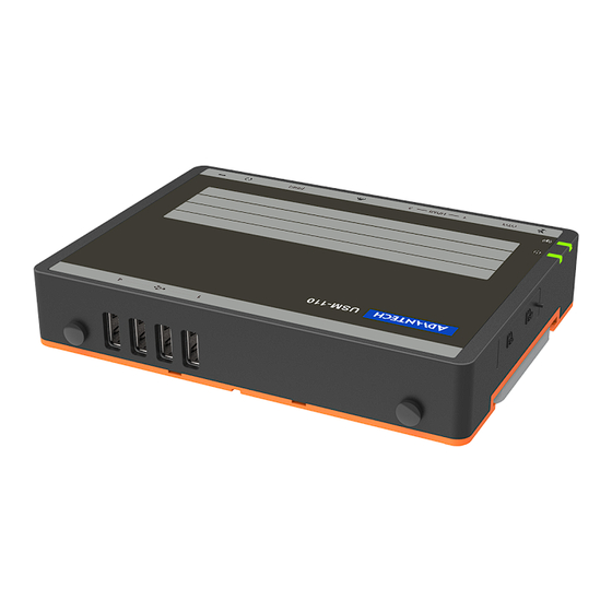
- Page 1 User Manual USM-110 Mini Digital Signage Player with Arm® Cortex®-A17 Quad-Core Processor...
- Page 2 No part of this manual may be reproduced, copied, translated, or transmitted in any form or by any means without the prior written permission of Advantech Co., Ltd. The information provided in this manual is intended to be accurate and reliable.
- Page 3 Consult the dealer or an experienced radio/TV technician for assistance. Technical Support and Assistance Visit the Advantech website at www.advantech.com/support to obtain the latest product information. Contact your distributor, sales representative, or Advantech's customer service center for technical support if you need additional assistance. Please have the following information ready before calling: –...
- Page 4 Discard used batteries according to the manufacturer's instructions.” Note! Notes provide additional optional information. Document Feedback To assist us with improving this manual, we welcome all comments and constructive criticism. Please send all feedback in writing to support@advantech.com. USM-110 User Manual...
- Page 5 In accordance with IEC 704-1:1982 specifications, the sound pressure level at the operator’s position does not exceed 70 dB (A). DISCLAIMER: These instructions are provided according to IEC 704-1 standards. Advantech disclaims all responsibility for the accuracy of any statements contained herein. USM-110 User Manual...
- Page 6 Transport: carry the unit with both hands and handle with care Maintenance: clean the surfaces using only approved products or a dry applicator European Contact Information Advantech Europe GmbH Kolberger Straße 7 D-40599 Düsseldorf, Germany Tel: 49-211-97477350 Fax: 49-211-97477300 USM-110 User Manual...
-
Page 7: Table Of Contents
Installation..........5 Quick Tour....................6 Figure 2.1 USM-110 Front View ..........6 Figure 2.2 USM-110 Rear View........... 6 Figure 2.3 USM-110 Standard I/O Layout ........6 Figure 2.4 USM-110 Delight I/O Layout........6 Installation Procedures................7 2.2.1 Connecting the Power Cord............7 2.2.2... - Page 8 Figure 5.3 Server Configuration ..........38 Figure 5.4 Device Edit Page - 1..........39 Figure 5.5 Device Edit Page - 2..........39 WISE-PaaS/SignageCMS Remarks ............40 Figure 5.6 Dual Display Support..........40 Figure 5.7 HDMI Output Layout..........40 USM-110 User Manual viii...
-
Page 9: Chapter 1 Overview
Chapter Overview... -
Page 10: Introduction
Moreover, USM-110 is integrated with Advantech’s WISE-Paas/SignageCMS digital signage management software, which allows users to layout, schedule, and dispatch signage content to USM-110 over the Internet. This enables remote delivery of diverse high-resolution multimedia to multiple client devices simultaneously. 1.2 Specifications 1.2.1 General Specifications... -
Page 11: Environmental Specifications
(PSE), it must comply with the IEEE 802.3at PoE standard. An IEEE 802.3at-qualified PSE will provide up to 30W power to USM-110. Only 25.5W power input is available for USM-110 because of transmitter dissipation. USM-110 can be connected to an AC power source and PSE simultaneously. -
Page 12: Dimensions
1.3 Dimensions Unit:mm Figure 1.1 USM-110 Standard Model Unit:mm 4- 4.4 28.3 Figure 1.2 USM-110 Delight Model USM-110 User Manual... -
Page 13: Chapter 2 Installation
Chapter Installation... -
Page 14: Quick Tour
SIM Card Slot USB2.0 Antenna SD Slot Line Out DC In RJ45 Antenna Antenna RS232/422/485 Figure 2.3 USM-110 Standard I/O Layout Wi Indicator Reset Power Indicator HDMI2.0 SD Slot S S D D Antenna A A ntenna USB2.0 Antenna USB2.0 A A nten n na... -
Page 15: Installation Procedures
2.3 Device Mounting To ensure flexible installation, the USM-110 digital signage player supports five mount options - wall, magnet, VESA, pole, and DI-rail mounting. Learn more about USM-110 mount options by watching the video at the links below. YouTube: https://youtu.be/c_yWG_WvkmQ Youku: http://v.youku.com/v_show/id_X- MzgyMTY4NDE4MA==.html?spm=a2h3j.8428770.3416059.1... -
Page 16: Wall Mount Installation
Attach the device to the mount bracket following the “Module Assembly” steps outlined previously. 2.3.4 Pole Mount Installation Step 1.Affix the mount bracket to the pole using cable ties (see above illustrations). Step 2.Attach the device to the mount bracket following the “Module Assembly” steps outlined previously. USM-110 User Manual... -
Page 17: Din-Rail Mount Installation
2.Attach the device to the mount bracket following the “Module Assembly” steps outlined previously. 2.3.6 Magnet Mount Installation Step 1.Place the device onto a flat metal surface. Step 2.Use the two magnets on the side wings to affix the device to the metal surface (Figure 7). USM-110 User Manual... -
Page 18: Expanded Module Installation
1.Unscrew the affixing screws and remove the orange rear cover. Step 2.Unscrew the screws circled in red below, and remove the bracket. Step 3.Install the Wi-Fi or 4G module into the M.2 or mini PCIe slot, respectively. USM-110 User Manual... - Page 19 Insert an antenna cable into the module (see the image below for reference). Insert antenna cable here Insert antenna cable here Fixed screw Fixed screw 4G module Mini PCIe slot Wi-Fi module M.2 slot Step 5.Remove the two rubber plugs that cover the antenna holes. Attach the antenna connectors. USM-110 User Manual...
- Page 20 Step 6.Attach the antennas to the antenna connectors Step 7.Replace the bracket and orange rear cover and secure in place. USM-110 User Manual...
-
Page 21: Jumper Settings
2.5 Jumper Settings 2.5.1 Jumper Description Users can configure USM-110 according to their specific application requirements by setting jumpers. A jumper is the simplest type of electrical switch and consists of two metal pins and a small metal clip (typically protected by a plastic cover) that slides over the pins to connect them. -
Page 22: Jumper And Connector Locations
COM4 RS485/RS422 Impedance Select JSETCOM4 COM4 RS232/RS422/RS485 Mode Select 2 2.5.4 Jumper Settings Table 2.2: SW3: AT & ATX Mode Switch Setting Function (1-2) ATX Mode (default A201-01 version) (2-2) Floating (2-3) AT Mode (default A101-01 version) USM-110 User Manual... - Page 23 Table 2.5: CN14: COM4 RS-232/422/485 Mode Select 1 Setting Function (1-2) RS-232/422 Mode (default) (2-3) RS-485 Mode Table 2.6: CN15: COM4 RS-485/422 Impedance Select Setting Function (1-3) RS-485 Impedance Off (default) (3-5) RS-485 Impedance On (1-3)&(2-4) RS-422 Impedance Off (default) (3-5)&(4-6) RS-422 Impedance On USM-110 User Manual...
- Page 24 Table 2.7: JSETCOM4 COM4 RS-232/422/485 Mode Select 2 Setting Function (5-6) (7-9) (8-10) (13-15) (14-16) RS-232 Mode (default) (3-4) (9-11) (10-12) (15-17) (16-18) RS-422 Mode (1-2) (9-11) (10-12) (15-17) (16-18) RS-485 Mode USM-110 User Manual...
-
Page 25: Chapter 3 Software
Chapter Software... -
Page 26: Operating System Updates
3.1 Operating System Updates The USM-110 ultra-compact digital signage player is pre-installed with the latest OS version. However, users may wish to update or change the OS. This chapter explains the procedures for OS installation and upgrade. Note! Some distributors and system integrators may have pre-installed system software prior to shipment. -
Page 27: Firmware Update Via Sd Card
3.1.2 Firmware Update via SD Card Preparation One computer equipped with Windows OS One micro SD card (at least 4 GB storage) Download “SD_Firmware_Tool._v1.46” from the Advantech website 3.1.2.1 SD Card Configuration Step 1.Execute “SD_Firmware_Tool._v1.46\SD_Firmware_Tool.exe” Step 2.Insert the SD card into the device and configure the firmware tool as explained below: Item 1. - Page 28 5.Another pop-up dialog window will appear, click the “ 确定 ” button. 3.1.2.2 Device Image Update Insert the SD card into the USM-110 SD slot and power on the device. Follow the instructions provided on screen to complete the update process. Upon completion, remove the SD card and restart the device.
-
Page 29: Operating System Change (Via Otg)
Configure the CN7 jumper by connecting Pins 1 and 2 instead of the default position of Pins 2 and 3 (refer to the red arrow in Figure 3.1). Power on the USM-110 digital signage player and connect it to a client device via OTG. - Page 30 Figure 3.1 USM-110 Mainboard Note! 1. The OTG cable must have a 5.8 mm jack connector. 2. The OTG cable must feature an ID pin (to facilitate data transfers). 5.8 mm USM-110 User Manual...
- Page 31 2-3. Click “Run”. The status of the burn process will be displayed in the right frame of the user interface. After image burning is complete, the user interface will report “found one loader device”. USM-110 User Manual...
-
Page 32: System Development
This chapter introduces the USM-110 software development process to allow users to develop unique application(s). Because USM-110 is designed to support a Linux host, developing on a Windows/ Android-based PC may result in compatibility issues. Currently, the officially sup- ported host OS version is Ubuntu 14.04 LTS (64 bit). - Page 33 Execute the Android launch command. In this example, the setup is for the produc- tion image of the Advantech RISC platform device with user debug type. If your ”. device is RSB4680, the system will send the command “launch rsb4680-userdebug...
-
Page 34: Uart
Typically, the UART RTS signal is used to switch the transmitter on and off. COM Name Device Node Remark UART0 /dev/ttyS0 for BT data COM1 /dev/ttyS1 COM2 /dev/ttyS2 Debug port/RS232 COM3 /dev/ttyS3 COM4 /dev/ttyS4 Support RS-485/422 USM-110 User Manual... -
Page 35: System Setup
Chapter System Setup... -
Page 36: Apk Installation
4.1 APK Installation Step 1.Navigate to the USM-110 program menu and click on the “Apkinstaller” icon. Step 2. Choose the “Install” option. Step 3. Select the storage disc where the APK is located. Step 4.Select the APK that you want to install. - Page 37 Step 5.Click “Install”. Step 6.Click “Done” to complete the APK installation. USM-110 User Manual...
-
Page 38: Apk Uninstall/Removal
1.In the program menu, click the “Settings” icon to access the system settings functions. Step 2.Click on the “Apps” item, and select the APK to remove from the app list. Step 3.Click the “Uninstall” button to initiate the uninstall process. USM-110 User Manual... -
Page 39: System Settings
Step 4.Select “OK” to begin uninstalling. 4.3 System Settings 4.3.1 Screen Rotate Step 1.In the program menu, click the “Settings” icon to access the system settings functions. Step 2.Click on the “Display” item. USM-110 User Manual... - Page 40 Step 3.Select the “Screen rotation” function. Step 4.Choose the desired rotation degree. USM-110 User Manual...
-
Page 41: Rs-232/422/485 Settings
4.3.2 RS-232/422/485 Settings Remove the USM-110 top cover. Locate the COM4 connector. USM-110 User Manual... - Page 42 Reference Figure 4.1 in the USM-110 user manual (shown below) to configure the RS-232/422/485 jumper settings. Figure 4.1 RS-232/422/485 Jumper Settings USM-110 User Manual...
-
Page 43: Wise-Paas/Signagecms
Chapter WISE-PaaS/ SignageCMS... -
Page 44: Wise-Paas/Signagecms Architecture
The server software must be installed on a Windows OS; however, the client software can be installed on various OS. To ensure convenient operation, the USM-110 digital signage player is pre-installed with the relevant client software. Advantech’s WISE-PaaS/SignageCMS software allows users to connect to the server remotely via any web-based browser (the net- work must be in the same network segment). -
Page 45: Wise-Paas/Signagecms Configuration
Make note of the [Client ID] or [Custom ID] (if the “Use Custom ID” checkbox is selected*). Click the “Silent Installation” checkbox to enable automatic updates. *The [Client ID] or [Custom ID] is required for the [Client Device] field in the server system settings. USM-110 User Manual... - Page 46 Option 1. If [Use Custom ID] is selected, input the [Custom ID] value set in the client system. – Option 2. If [Use Custom ID] is not selected, input the [Client ID] value set in the client system. Click [Save & Exit]. USM-110 User Manual...
- Page 47 Navigate to the Device page of the interface to access the device list. Check the Status column. A green check (as shown in Figure 5.5) means that the device has been added successfully. Figure 5.5 Device Edit Page - 2 USM-110 User Manual...
-
Page 48: Wise-Paas/Signagecms Remarks
5.3 WISE-PaaS/SignageCMS Remarks The USM-110 device’s primary output is HDMI1. HDMI2 is a secondary output. Use of an extension module may be influenced by the following limitations: Audio input is only supported on HDMI1. Mouse, keyboard, and touch control is only supported on HMDI1. - Page 49 USM-110 User Manual...
- Page 50 No part of this publication may be reproduced in any form or by any means, such as electronically, by photocopying, recording, or otherwise, without prior written permission from the publisher. All brand and product names are trademarks or registered trademarks of their respective companies. © Advantech Co., Ltd. 2021...
- Page 51 PWS-430 User Manual...
Need help?
Do you have a question about the USM-110 and is the answer not in the manual?
Questions and answers