Table of Contents
Advertisement
Quick Links
Advertisement
Table of Contents

Related Manuals for Advantech USB-4750


Summary of Contents for Advantech USB-4750
-
Page 1: User Manual
USB-4750 32-Channel Isolated Digital I/O USB Module User Manual... - Page 2 No part of this man- ual may be reproduced, copied, translated or transmitted in any form or by any means without the prior written permission of Advantech Co., Ltd. Information provided in this manual is intended to be accurate and reli- able.
- Page 3 Product Warranty (2 years) Advantech warrants to you, the original purchaser, that each of its prod- ucts will be free from defects in materials and workmanship for two years from the date of purchase. This warranty does not apply to any products which have been repaired or...
- Page 4 This product has passed the CE test for environmental specifications when shielded cables are used for external wiring. We recommend the use of shielded cables. This kind of cable is available from Advantech. Please contact your local supplier for ordering information.
-
Page 5: Table Of Contents
Chapter 1 Introduction ... 2 Hardware Features... 2 Software Overview... 3 1.2.1 Chapter 2 Installation ... 6 Unpacking ... 6 Driver Installation ... 7 Hardware Installation ... 9 Hardware Uninstallation ... 9 Chapter 3 Signal Connections ... 12 Overview ... 12 I/O Connectors ... - Page 6 USB-4750 User Manual...
- Page 7 Introduction Sections include: • Hardware Features • Software Overview...
-
Page 8: Chapter 1 Introduction
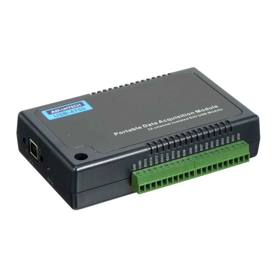
Chapter 1 Introduction Thank you for buying the Advantech’s USB-4750 data acquisition mod- ule. The Advantech USB-4750 is a powerful data acquisition (DAS) module for the USB port. It features a unique circuit design and complete functions for data acquisition and control. -
Page 9: Software Overview
1.2 Software Overview Advantech offers a rich set of DLL drivers, third-party driver support and application software on the companion CD-ROM to help fully exploit the functions of your device. Advantech’s Device Drivers feature a complete I/O function library to help boost your application performance and work seamlessly with development tools such as Visual C++, Visual Basic, Inprise C++ Builder, and Inprise Delphi. - Page 10 USB-4750 User Manual...
- Page 11 Installation Sections include: • Unpacking • Driver Installation • Hardware Installation • Hardware Uninstallation...
-
Page 12: Chapter 2 Installation
Chapter 2 Installation 2.1 Unpacking After receiving your USB-4750 package, please inspect its contents first. The package should contain the following items: • USB-4750 Module • Shielded USB 2.0 Cable (1.8 m) • Companion CD-ROM (DLL driver included) • User Manual The USB-4750 Module harbors certain electronic components vulnerable to electrostatic discharge (ESD). -
Page 13: Driver Installation
2.2 Driver Installation We recommend you install the software driver before you install the USB-4750 module into your system, since this will guarantee a smooth installation process. The 32-bit DLL driver Setup program for the USB-4750 module is included on the companion CD-ROM that is shipped with your module package. - Page 14 For further information on driver-related issues, an online version of the Device Drivers Manual is available by accessing the following path: Start\Programs\Advantech Automation \Device Manager\Device Driver’s Manual USB-4750 User Manual...
-
Page 15: Hardware Installation
2.2 Driver Installation) After the DLL driver installation is completed, you can now go on to install the USB-4750 module in any USB port that supports the USB 1.1/2.0 standard, on your computer. It is suggested that you refer to the computer’s user manual if you have any doubts. -
Page 16: Figure 2.2:Stop A Hardware Device Dialog Box
Step2: Right click the “Unplug or Eject Hardware” icon on your task bar. Figure 2.1: Unplug or Eject Hardware Dialog Step3: Select “Advantech USB-4750 Device” and press “Stop” Button. Figure 2.2: Stop a Hardware device dialog box Step4: Unplug your USB device from the USB port. - Page 17 Signal Connections Sections include: • Overview • Isolated Digital I/O Connections • Field Wiring Considerations...
-
Page 18: Figure 3.1:I/O Connector Pin Assignment
A good signal connection can avoid unnecessary and costly damage to your PC and other hardware devices. 3.2 I/O Connectors USB-4750 is equipped with plug-in screw-terminal connectors that facili- tate connection to the module without terminal boards or cables. 3.2.1 Pin Assignments Figure 3.1: I/O Connector Pin Assignment... -
Page 19: Table 3.1:I/O Connector Signal Descriptions
3.2.2 I/O Connector Signal Description Table 3.1: I/O Connector Signal Descriptions Signal Reference Direction Description IDI<0~15> INT<0,1> INT_G INT<0,1>_ CNT<0,1> IDO<0~15> COM<0,1> 3.2.3 LED Indicator Status Description The USB Module is equipped with a LED indicator to show the current status of the device. -
Page 20: Figure 3.2:Isolated Digital Input Connections
Figure 3-1 shows external circuitry with both wet and dry contact components, con- nected as an input source to one of the card's digital input channels. Figure 3.2: Isolated Digital Input Connections USB-4750 User Manual... -
Page 21: Figure 3.3:Isolated Digital Output Connections
3.3.2 Isolated Digital Output Connections Each of 8 isolated digital output channels comes equipped with a Darling- ton transistor. Every 8 output channels share common collectors and inte- gral suppression diodes for inductive loads. Channels 0 ~ 7 use COM0, and channels 8 ~ 15 use COM1 as a common pin. -
Page 22: Field Wiring Considerations
3.4 Field Wiring Considerations • When you use USB-4750 to acquire data from outside, noises in the environment might significantly affect the accuracy of your measure- ments if due cautions are not taken. The following measures will be helpful to reduce possible interference running signal wires between signal sources and the USB-4750. - Page 23 Specifications...
-
Page 24: A.3 Isolated Counter
A.4 General I/O Connector Type 10-pin screw terminal *4 Dimensions Power Consumption 5 V @ 350 mA max. Temperature Relative Humidity USB-4750 User Manual DI0, DI8 2500 VDC 25 µs 5~50VDC, or dry contact 2500 VDC 5 ~ 40 VDC 100mA/ch.
Need help?
Do you have a question about the USB-4750 and is the answer not in the manual?
Questions and answers