Table of Contents
Advertisement
Quick Links
Advertisement
Table of Contents

Related Manuals for Advantech ROM-2620


Summary of Contents for Advantech ROM-2620
- Page 1 User Manual ROM-2620 NXP i.MX 8ULP 1200 Cortex®- A35 OSM 1.1 Computer-on- Module...
- Page 2 No part of this manual may be reproduced, copied, translated or transmitted in any form or by any means without the prior written permission of Advantech Co., Ltd. Information provided in this manual is intended to be accurate and reliable. How- ever, Advantech Co., Ltd.
- Page 3 60°C (32 ~140 °F) i.MX8ULP OSM V1.1 S module, 1GB DDR, 16GB eMMC, -40 ROM-2620WD-MDA1E ~ 85 °C (-40 ~158 °F) Packing List Before installation, please ensure the following items have been shipped: 1 x ROM-2620 ROM-2620 User Manual...
- Page 4 IEEE802.11ax+BT 5.2 2T2R MT7921L M.2 2230 1750007965-01 Wi-Fi Coaxial Cable, SMA (M) to MHF4, 30 cm 1750008717-01 Wi-Fi 2.4 GHz and 5 GHz Dipole Antenna *Please contact us for suggestions on suitable cellular modules for your region. ROM-2620 User Manual...
- Page 5 The equipment has been dropped and damaged. The equipment has obvious signs of breakage. DISCLAIMER: This set of instructions is given according to IEC 704-1. Advantech disclaims all responsibility for the accuracy of any statements contained herein. Safety Precaution - Static Electricity Follow these simple precautions to protect yourself from harm and the products from damage.
- Page 6 ROM-2620 User Manual...
-
Page 7: Table Of Contents
Camera ....................21 3.11.1 MIPI-CSI0 (Tested with OV5640 + mini-SAS to MIPI-CSI Cable) .. 3.12 PWM ....................... 21 3.13 M33 Function ..................22 3.13.1 CAN Bus ..................23 3.13.2 QSPI ................... 23 3.13.3 LPSPI..................24 3.13.4 LPUART..................24 ROM-2620 User Manual... - Page 8 Chapter Embedded OS ........27 Introduction ..................... 28 4.1.1 Device Tree Source File Select for ROM-2620 ......28 4.1.2 Module ..................28 Chapter System Recovery ......29 System Recovery..................30 5.1.1 Recovery by UUU Tool ............... 30 Chapter Advantech Services......31 RISC Design-In Services ................
-
Page 9: Chapter 1 General Introduction
Chapter General Introduction This chapter details background information on the ROM-2620. Sections include: Introduction Specifications... -
Page 10: Introduction
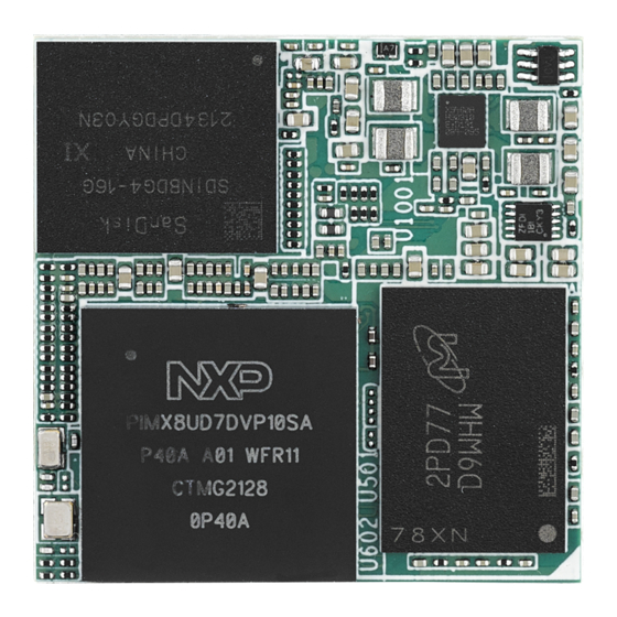
Introduction Advantech's ROM-2620 is powered by NXP i.MX 8ULP processor, featuring 2 Arm Cortex-A35 cores. Additionally, it incorporates 2 Arm Cortex-M33 cores for real-time responsiveness. The Cortex-M33 is capable of reducing static power consumption to 36 microwatts, making it suitable for applications that require extended battery life. -
Page 11: Mechanical Specifications
Operating Temperature: 0 ~ 60 °C/32 ~ 140 °F; -40 ~ 85 °C/-40 ~ 185 °F Operating Humidity: 5 ~ 95% relative humidity, non-condensing Storage Temperature: -40 ~ 85 °C/-40~185 °F Storage Humidity: 60 °C/140 °F @ 95% RH non-condensing ROM-2620 User Manual... - Page 12 ROM-2620 User Manual...
-
Page 13: Chapter 2 H/W Installation
Chapter H/W Installation This chapter details mechanical and connector information. Sections include: Mechanical Drawing Pin Define ? Quick Start Guide... -
Page 14: Board Dimensions
1GB LPDDR4 SPI x 1 NXP ARM Cortex-A35 I2S x 1 i.MX 8ULP 1.0GHz 16 GB eMMC MIPI-CSI MIPI DSI PWM x 6 NXP PMIC GPIO x 24 RMII USB 2.0 x 1 USB OTG x 1 ROM-2620 User Manual... -
Page 15: Pin Define
JTAG_nTRST JTAG0_TRST# UART Contact Name Contact Acronym ROM-2620 UART_A_RX LPUART4_RX UART_A_TX LPUART4_TX UART_A_RTS LPUART4_RTS# UART_A_CTS LPUART4_CTS# UART_B_RX LPUART2_RX UART_B_TX LPUART2_TX UART_B_RTS LPUART2_RTS# Size-S UART_B_CTS LPUART2_CTS# UART_C_RX LPUART6_RX UART_C_TX LPUART6_TX UART_D_RX LPUART5_RX UART_D_TX LPUART5_TX UART_CON_RX LPUART1_RX UART_CON_TX LPUART1_TX ROM-2620 User Manual... - Page 16 GPIO_A_6/SPI_A_CS1# FLEXSPI0_A_SS1# GPIO_A_7/SPI_B_CS1# LPSPI3_PCS1# GPIO_B_0 GPIO_B_0 GPIO_B_1 GPIO_B_1 GPIO_B_2 GPIO_B_2 GPIO_B_3 GPIO_B_3 Size-S GPIO_B_4 GPIO_B_4 GPIO_B_5 GPIO_B_5 GPIO_B_6 GPIO_B_6 GPIO_B_7 GPIO_B_7 GPIO_C_0 GPIO_C_0 GPIO_C_1 GPIO_C_1 GPIO_C_2 GPIO_C_2 GPIO_C_3 GPIO_C_3 GPIO_C_4/DISP_VDD_EN DISP_VDD_EN GPIO_C_5/DISP_BL_EN DISP_BL_EN GPIO_C_6/CAM_PWR CAM_PWR GPIO_C_7/CAM_RST# CAM_RST# ROM-2620 User Manual...
- Page 17 I2S_LRCLK I2S7_TX_FS I2S_BITCLK I2S7_TX_BCLK Contact Name Contact Acronym ROM-2620 CAN_A_TX AC17 CAN0_TX Size-S CAN_A_RX AB17 CAN0_RX Contact Name Contact Acronym ROM-2620 USB_A_D_N AB13 USB_A_DN USB_A_D_P AC14 USB_A_DP Size-S USB_A_ID AB14 USB_A_ID USB_A_OC# AC15 USB_A_OC# USB_A_VBUS AB16 USB_A_VBUS_DET ROM-2620 User Manual...
- Page 18 Contact Acronym ROM-2620 CSI_DATA0_N CSI_DATA0_N CSI_DATA0_P CSI_DATA0_P CSI_DATA1_N CSI_DATA1_N CSI_DATA1_P CSI_DATA1_P CSI_DATA2_N CSI_DATA2_P CSI_DATA3_N Size-S CSI_DATA3_P CSI_CLOCK_N CSI_CLK_N CSI_CLOCK_P CSI_CLK_P 24M OSC Should Design CAM_MCK on Carrier Board [1] I2C_CAM_SDA / CSI_TX_N LPI2C0_SDA I2C_CAM_SCL / CSI_TX_P LPI2C0_SCL ROM-2620 User Manual...
-
Page 19: Quick Start Guide
2.4.1 Debug Port Connection and Setting ROM-2620 debug port is shared with A-core Console. Please connect the debug console cable 1700021565-01 & 1700019474. Then connect the USB-to-RS232 Cable to your PC terminal. Connect the cable to COM1 pin header to the nearby the HDMI connector. - Page 20 Figure 2.1 Connect a Display: ROM-2620's default display interface is LVDS. When you use LVDS display as an example, please connect the LVDS display cable to ROM-2620's LVDS connector as shown in Figure 2.2.
- Page 21 Connect the Power Source: ROM-2620's power input is 12VDC. The power interface's location is DCIN1. Please choose a suitable adapter and power cord to connect the board (please refer to P/Ns on datasheet and Optional Accessories of this manual) as shown in Figure 2.3.
- Page 22 After booting, the display boot screen and debug window are shown as pictures below. Login username: root without password. ROM-2620 User Manual...
-
Page 23: Chapter 3 Software Functionality
Chapter Software Functionality This chapter details the software functions on the ROM-2620. -
Page 24: Display
Backlight Power: 12V) Connect G070VW01 LVDS panel with the LVDS cable. Connect this to the LVDS. Connect the Backlight cable to LVDS_BKLT_PWR. Power on ROM-2620. 3.1.1.2 Dual Channel LVDS Panel: G215HVN0 (VDD: 5V, Backlight Power: 12V) Connect G215HVN0 LVDS panel with the LVDS cable. Connect this to the LVDS. -
Page 25: Test Wi-Fi With Ewm-W194M201E Module (Sdio Interface)
Please refer to the 3.3.1 step 2. Bluetooth test command. # hciconfig hci0 up # bluetoothctl # discoverable on # pairable on # scan on [NEW] FC:18:3C:8D:75:F4 myphone # scan off # pair FC:18:3C:8D:75:F4 # connect FC:18:3C:8D:75:F4 ROM-2620 User Manual... -
Page 26: Serial Port (Com A/C)
Adam-4520 RX- <-->ROM-2620 COMA DB9 Pin 1, Adam-4520 RX+ <-->ROM-2620 COMA DB9 Pin 2, Adam-4520 TX- <-->ROM-2620 COMA DB9 Pin 4, Adam-4520 TX+ <--> ROM-2620 COMA DB9 Pin 3 Run below command: # stty -F /dev/ttyLP0 speed 115200 ignbrk -brkint -icrnl -imaxbel -opost - onlcr -isig -icanon -iexten -echo -echoe -echok -echoctl -echoke # cat /dev/ttyLP0 &... -
Page 27: Usb
Test command: # dd if=/dev/urandom of=data bs=1 count=1024 # dd if=/dev/mmcblk0 of=backup bs=1 count=1024 skip=4096 # dd if=data of=/dev/mmcblk0 bs=1 seek=4096 # dd if=/dev/mmcblk0 of=data1 bs=1 count=1024 skip=4096 # diff data data1 # dd if=backup of=/dev/mmcblk0 bs=1 seek=4096 ROM-2620 User Manual... -
Page 28: Ethernet
3.10 GPIO 3.10.1 GPIO Pins Table 3.1: GPIO Pins Numbers GPIO1 GPIO2 GPIO3 GPIO4 GPIO5 GPIO6 GPIO7 GPIO8 GPIO9 GPIO10 437 (Use for SDIO) GPIO11 438 (Use for M2_UART) GPIO12 439 (Use for M2_UART) GPIO13 GPIO14 GPIO15 ROM-2620 User Manual... -
Page 29: Gpio Loopback Test (Using Gpio1 And Gpio2 As Examples)
# echo 4 > /sys/class/pwm/pwmchip0/export # echo 1000000 > /sys/class/pwm/pwmchip0/pwm4/period # echo 500000 > /sys/class/pwm/pwmchip0/pwm4/duty_cycle # echo 1 > /sys/class/pwm/pwmchip0/pwm4/enable PWM2: # echo 5 > /sys/class/pwm/pwmchip6/export # echo 1000000 > /sys/class/pwm/pwmchip6/pwm5/period # echo 500000 > /sys/class/pwm/pwmchip6/pwm5/duty_cycle # echo 1 > /sys/class/pwm/pwmchip6/pwm5/enable ROM-2620 User Manual... -
Page 30: M33 Function
LPSPI master Press for test mode of LPSPI slave Press for test mode of LPUART About this firmware, user should note that if you want to switch to another test mode, you must reboot the system. ROM-2620 User Manual... -
Page 31: Can Bus
3.13.1 CAN Bus Prepare two pcs rom-2620. One for 'Node A' one for 'Node B' Connect these two boards (HI-HI/LO-LO) The test steps and screen are as below : Follow the figure (step1 - step4). If B node received data means test successful. -
Page 32: Lpspi
3.13.3 LPSPI Two pcs rom-2620. One for 'Master' one for 'Slave'. Connection with these two boards by SPI Bus as below: LPSPI3_PCS0-- LPSPI3_PCS0 LPSPI3_GND-- LPSPI3_GND LPSPI3_PCS1-- LPSPI3_PCS1 LPSPI3_SCK-- LPSPI3_SCK LPSPI3_SOUT-- LPSPI3_SIN LPSPI3_SIN-- LPSPI3_SOUT One board select mode 'M' to be Master. - Page 33 After select the test mode 'U' to verify LPUART2, you will see below screen. If tester can input any characters/strings and show that at COM-B means test successful. ROM-2620 User Manual...
- Page 34 ROM-2620 User Manual...
-
Page 35: Embedded Os
Chapter Embedded OS This chapter introduces Linux systems instructions... -
Page 36: Introduction
O.S. (Linux kernel 5.15.52). It contains all the system-required shell commands and drivers needed to operate the platform. We do not offer IDE developing environment on ROM-2620 BSP. Users can evaluate and develop their device using the Ubuntu 20.04 LTS environment. -
Page 37: System Recovery
Chapter System Recovery This chapter details system recov- ery for damaged Linux os... -
Page 38: System Recovery
UUU command to flash eMMC. # tar zxvf 2620A1AIM36LIVD0032_iMX8ULP_1G_imx-boot.tgz # tar zxvf 2620A1AIM36LIVD0032_iMX8ULP_1G_flash_tool.tgz # sudo ./uuu -b emmc_all 2620A1AIM36LIVD0032_iMX8ULP_1G_imx-boot/imx-boot- imx8ulprom2620a1-1G.bin-flash_singleboot_m33 2620A1AIM36LIVD0032_iMX- 8ULP_1G_flash_tool/image/imx-image-full-imx8ulprom2620a1- 20240117122318.rootfs.wic Enter ROM-2620 eMMC Boot mode by change SW1301 and SW1302 as below: Reboot the system. ROM-2620 User Manual... -
Page 39: Advantech Services
Chapter Advantech Services This chapter outlines Advantech's Design-In services, technical sup- port, and warranty policy for ROM- 2620. -
Page 40: Risc Design-In Services
Comprehensive document support Design Assistance Service Advantech provides a checklist for engineers to check their schematics and review services based on customer carrier board schematics. These services prevent design errors before they occur. This saves time and reduces costs associated with developing carrier boards. - Page 41 R&D costs and hardware investment. By virtue of a cooperative relationship with leading original manufacturers of CPUs and chipsets - such as ARM, TI, and NXP - Advantech helps solve communication and technical support difficulties. This can reduce the uncertainties in product devel- opment.
- Page 42 I/O and perfor- mance. Advantech also offers software evaluation and peripheral module recommen- dations (such as WiFi, 3G, BT). At this stage, Advantech seeks to resolve customer concerns. Product evaluation with a focus on performance and specification is vital during the planning period.
-
Page 43: Contact Information
Korea (Toll Free) 080-363-9495 Taiwan (Toll Free) 0800-777-111 Russia (Toll Free) 8-800-555-01-50 Alternatively, you can contact the Advantech service team via our website. http://www.advantech.com.tw/contact/default.aspx?page=contact_form2&sub- ject=Technical+Support Our technical support engineers will provide a quick response to your queries ROM-2620 User Manual... -
Page 44: Technical Support And Assistance
The DOA cross-shipment excludes any shipping damage, customized and/or build- to-order products. For products that are not DOA, the return fee to an authorized Advantech repair facil- ity will be at the customer's expense. The shipping fee for reconstructed products from Advantech back to the customer will be at Advantech's expense. -
Page 45: Repair Process
"Attn. RMA Service Department". All products must be returned in properly packed ESD material or anti-static bags. Advantech reserves the right to return unrepaired items at the customer's cost if inap- propriately packed. Door-to-Door transportation, such as speed post, is recommended for delivery. Oth- erwise, the sender should bear additional charges such as clearance fees if air cargo shipment methods are used. - Page 46 tomer who is without warranty. If a product has been repaired by Advantech, and within three months after such a repair the product requires another repair for the same problem, Advantech will con- duct the repair free of charge. However, free repairs do not apply to products that have been misused, abused, or subjected to unauthorized disassembly/modification;...
- Page 47 ROM-2620 User Manual...
- Page 48 No part of this publication may be reproduced in any form or by any means, electronic, photocopying, recording, or otherwise, without prior written permis- sion from the publisher. All brand and product names are trademarks or registered trademarks of their respective companies. © Advantech Co., Ltd. 2024...
Need help?
Do you have a question about the ROM-2620 and is the answer not in the manual?
Questions and answers