Table of Contents
Advertisement
Quick Links
Advertisement
Table of Contents

Related Manuals for Advantech RSB-3720


Summary of Contents for Advantech RSB-3720
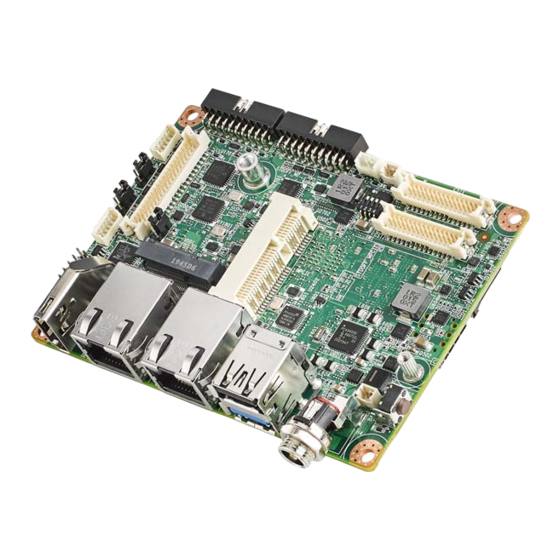
- Page 1 User Manual RSB-3720 NXP i.MX8M Plus Cortex®-A53 2.5" SBC with UIO40-Express...
- Page 2 The documentation and the software included with this product are copyrighted 2020 by Advantech Co., Ltd. All rights are reserved. Advantech Co., Ltd. reserves the right to improve the products described in this manual at any time without notice. No part of this manual may be reproduced, copied, translated, or transmitted in any form or by any means without the prior written permission of Advantech Co., Ltd.
- Page 3 Packing List Before installation, ensure that the following items have been shipped: 1 x RSB-3720 SBC (With Heat Sink: 1970004819T001) Safety Precautions – Static Electricity Follow this simple precaution to protect yourself from harm and the products from...
- Page 4 The equipment has been dropped and damaged. – The equipment shows obvious signs of breakage. DISCLAIMER: These instructions are provided according to IEC 704-1 standards. Advantech disclaims all responsibility for the accuracy of any statements contained herein. Ordering Information Part No.
- Page 5 Antenna Cable R/P SMA (M) to MHF4, 300mm EWM-C117FL06E* LTE 4G,3G WCDMA/DC-HSPA+, 2G module, MPCI-L280H 1750007990-01 Antenna 4G/LTE full band L=11 cm 50 Ohm 1750006009 Antenna Cable SMA (F) to MHF 1.32 25cm *Please contact us for suggesting suitable cellular module for your region. RSB-3720 User Manual...
-
Page 6: Table Of Contents
Figure 2.26GPIO Pin Header ............32 Figure 2.27SPI Pin Header ............33 Figure 2.28I2C Connector ............33 LED ......................34 Quick Start Guide ..................34 2.6.1 Debug Port Connection ............... 34 2.6.2 Debug Port Setting ..............35 Chapter Software Functionality ..... RSB-3720 User Manual... - Page 7 3G/4G ..................50 3.9.4 Ethernet ..................51 3.10 IIC ......................52 Chapter Advantech Services ......RISC Design-In Services................54 Contact Information .................. 57 Global Service Policy ................58 4.3.1 Warranty Policy ................58 4.3.2 Repair Process ................58 RSB-3720 User Manual...
-
Page 8: Chapter 1 General Introduction
Chapter General Introduction This chapter includes background information regarding RSB-3720. Introduction Specification... -
Page 9: Introduction
Edge AI inference at 2.3 TOPS to perform well on Object Detection as well as Image Segmentation. To stand on the front of the Edge AI trend, RSB-3720, a compact-sized 2.5" Single Board Computer is best used for Edge AI Gateway and vision-based system for factory automation. -
Page 10: Mechanical Specifications
Operating Temperature: 0 ~ 60 °C/32 ~ 140 °F; -40 ~ 85 °C/-40 ~ 185 °F Operating Humidity: 5 ~ 95% relative humidity, non-condensing Storage Temperature: -40 ~ 85 °C/-40~185 °F Storage Humidity: 60 °C/140 °F @ 95% RH non-condensing RSB-3720 User Manual... -
Page 11: Block Diagram
Dual Channel UIO2 UART3(4-wire) I2C1 LVDS (Default configured 232/422/485 as debug console) BKLT Backlight CP339 Header Connector x2 FlexCAN1 4-Lane MIPI-CSI2-1 Transceiver Connector I2C2 FlexCAN2 4-Lane MIPI-CSI2-2 Support CAN-FD in Wide temp. SKUs: RSB-3720WQ/ RSB-3720WD Connector I2C3 RSB-3720 User Manual... -
Page 12: Chapter 2 Hardware Installation
Chapter Hardware Installation This chapter provides mechanical and connector information. Jumper Information Connector Information Mechanical Drawing Quick Start Guide... -
Page 13: Jumper And Connector Locations
Jumper and Connector Locations RSB-3720 User Manual... -
Page 14: Board Dimensions
Board Dimensions RSB-3720 User Manual... -
Page 15: Jumpers
Generally, only a standard cable is required to make most connections. Warning! To avoid damaging the computer, always turn off the power supply before setting jumpers. 2.3.2 Jumper List RSB-3720 User Manual... -
Page 16: Jumper Settings
2.3.3 Jumper Settings 2.3.3.1 BLP1 2.3.3.2 BLP2 RSB-3720 User Manual... - Page 17 2.3.3.3 VDD1 2.3.3.4 RSB-3720 User Manual...
-
Page 18: Connectors
Connectors 2.4.1 Connector List RSB-3720 User Manual... -
Page 19: Connector Settings
RSB-3720 supports 1 2-pin type connector for RTC Battery. Figure 2.1 BAT (RTC Battery CONN.) 2.4.2.2 BL1 (LVDS Backlight 1) RSB-3720 supports 1 LVDS Backlight CONN. for each channel, pin definition for the channel as below: Figure 2.1 BL1 (LVDS Backlight 1) RSB-3720 User Manual... - Page 20 2.4.2.4 COM1 (COM + CAN Pin Header): (default as debug console) RSB-3720 supports COM1 Pin Header for 1 4-wires COM port (Can be define as RS- 232/RS-422/RS-485 by S/W setting), default set as RS-232 debug console + 1 CANBus (Supports CAN-FD with industrial temp. SKU: RSB-3720WQ/RSB-3720WD) pin definition as below: Figure 2.4 COM1 (COM + CAN Pin Header)
- Page 21 2.4.2.5 CSI1 (MIPI-CSI Camera Input 1) RSB-3720 supports 2 4-Lane MIPI-CSI Camera Input CONNs, CSI1 is for MIPI-CSI1, pin definition as below: Figure 2.5 CSI1 (MIPI-CSI Camera Input 1) RSB-3720 User Manual...
- Page 22 2.4.2.6 CSI2 (MIPI-CSI Camera Input 2) RSB-3720 supports 2 4-Lane MIPI-CSI Camera Input CONNs, CSI2 is for MIPI-CSI2, pin definition as below: Figure 2.6 CSI2 (MIPI-CSI Camera Input 2) RSB-3720 User Manual...
- Page 23 2.4.2.7 DCIN/ DCIN1 (12V DC Power Input by DC Jack/ by Pin Header) Power input for RSB-3720 is 12V, we design DC Jack and 2 pin type Pin Header co-layout, default SKU is by lockable DC Jack. DCIN: (Default) Figure 2.7.1 DCIN (12V DC Jack) DCIN1 (By BOM Option): Figure 2.7.2 DCIN1 (12V DC-IN Pin Header)
- Page 24 2.4.2.8 HDMI (HDMI CONN.) RSB-3720 supports 1 HDMI 2.0 CONN. on the coast line. Figure 2.8 HDMI (HDMI CONN.) RSB-3720 User Manual...
- Page 25 2.4.2.9 LAN1 (Ethernet eth0) LAN1 supports 10M/100M/1G. Figure 2.9 LAN1 (Ethernet eth0) RSB-3720 User Manual...
- Page 26 2.4.2.10 LAN2 (Ethernet eth1) LAN2 supports 10M/100M/1G. Figure 2.10 LAN2 (Ethernet eth1) 2.4.2.11 LOUT (Line Out Pin Header) Figure 2.11 LOUT (Line Out Pin Header) RSB-3720 User Manual...
- Page 27 2.4.2.12 LVDS (LVDS CONN.) RSB-3720 supports 1 single channel LVDS @LVDS0, 1 4-Lane MIPI-DSI @LVDS1, and can be configured as 1 dual channel LVDS. Figure 2.12 LVDS (LVDS CONN.) RSB-3720 User Manual...
- Page 28 2.4.2.13 M2 (M.2 Key E CONN.) RSB-3720 supports 1 M.2 Key E CONN. for extension, interfaces: USB/PCIe/SDIO/UART/I2S. RSB-3720 User Manual...
- Page 29 Figure 2.13 M2 (M.2 Key E CONN.) RSB-3720 User Manual...
- Page 30 2.4.2.14 MIC (MIC In Pin Header) Figure 2.14 MIC (MIC In Pin Header) 2.4.2.15 MPCIE (Mini-PCIe CONN.) RSB-3720 supports 1 Full size Mini-PCIe CONN. for extension, interface: USB. RSB-3720 User Manual...
- Page 31 Figure 2.15 MPCIE (Mini-PCIe CONN.) 2.4.2.16 RST (Reset Button) Figure 2.16 RST (Reset Button) RSB-3720 User Manual...
- Page 32 2.4.2.17 SD (SD Slot) RSB-3720 supports 1 Micro SD Slot. Figure 2.17 SD (SD Slot) 2.4.2.18 SIM (SIM Slot) RSB-3720 supports 1 Nano SIM Slot. Figure 2.18 SIM (SIM Slot) RSB-3720 User Manual...
- Page 33 2.4.2.19 UIO1 (UIO40-Express Pin Header 1) RSB-3720 supports I/O extension by supporting UIO40-Express standard, UIO1 connector pinout is as the following: Figure 2.19 UIO1 (UIO40-Express Pin Header 1) RSB-3720 User Manual...
- Page 34 2.4.2.20 UIO2 (UIO40-Express Pin Header 2) RSB-3720 supports I/O extension by supporting UIO40-Express standard, UIO2 connector pinout is as the following: Figure 2.20 UIO2 (UIO40-Express Pin Header 2) RSB-3720 User Manual...
- Page 35 2.4.2.21 USB1 (USB 3.2 Gen 1 on TOP + USB 2.0 on BOT) Figure 2.21 USB1 (USB 3.2 Gen 1 on TOP + USB 2.0 on BOT) RSB-3720 User Manual...
-
Page 36: Led
HDMI connector. Note: Debug cable needs to be purchased separately. 2. RSB-3720 can communicate with a host server by using serial cables. Common serial communication programs such as HyperTerminal, Tera Term or PuTTY can be used in this case. The example as the below describes the serial terminal setup using Tera Term on a Windows host: Open Tera Term on your Windows PC, and select the settings as shown in Figure 2.3. - Page 37 3. Connect Display: RSB-3720’s default display interface is HDMI. When you use HDMI display as an example, please connect the HDMI display’s cable to RSB-3720’s HDMI connector as shown in Figure 2.4. Figure 2.4 4. Connect The Power Source: RSB-3720’s power input is 12VDC, power interface’s location is DCIN1, please...
- Page 38 BOT side of the board will be lit up to indicate that the board has booted up normally. (Figure 2.6) Figure 2.6 After booting, the display boot screen is shown in Figure 2.7. The debug window is shown in Figure 2.8. Figure 2.7 Figure 2.8 RSB-3720 User Manual...
-
Page 39: Software Functionality
Chapter Software Functionality This chapter details software functions on RSB-3720. - Page 40 Test Different Resolutions: Step 1: Disable Weston UI # killall -9 weston Step 2: Get “connect ID” and “support resolutions “ # modetest -c Step 3: Play colorbar of the specified resolution on HDMI # modetest -s 46:1920x1080-60 RSB-3720 User Manual...
- Page 41 Display test (single LVDS0 or single LVDS1) The default Weston UI will be displayed on the screen LVDS0 - g070vw01v0(VDD:3.3V, Backlight Power:12V) Step 1: Connect LVDS VDD and Backlight Power cable Step 2: power on Step 3: press enter after boot, system will stop at u-boot as below: Normal Boot Hit any key to stop autoboot: 0 u-boot=>...
- Page 42 Dual Channel LVDS - g215hvn0 (VDD:5V, Backlight Power:12V) Step 1: Connect two LVDS VDD and Backlight Power cable Step 2: power on Step 3: press enter after boot, system will stop at u-boot as below: Normal Boot Hit any key to stop autoboot: 0 u-boot=>...
- Page 43 Display test (MIPI to HDMI) (VDD:3.3V, Backlight Power:5V) Step 1: Connect MIPI to HDMI cable to LVDS Step 2: power on Step 3: press enter after boot, system will stop at u-boot as below: Normal Boot Hit any key to stop autoboot: 0 u-boot=>...
- Page 44 Display test (MIPI DSI- g101uan02) (VDD:3.3V, Backlight Power:5V) Step 1: Connect LVDS VDD and Backlight Power cable Step 2: power on Step 3: press enter after boot, system will stop at u-boot as below: Normal Boot Hit any key to stop autoboot: 0 u-boot=>...
- Page 45 Audio test Check audio codec # cat /proc/asound/cards 0 [sgtl5000 ]: sgtl5000 - sgtl5000 sgtl5000 1 [audiohdmi ]: audio-hdmi - audio-hdmi audio-hdmi Audio codec(sgtl5000): Set MIC and headphone # amixer set Mic 32% Simple mixer control 'Mic',0 Capabilities: volume volume-joined Playback channels: Mono Capture channels: Mono...
- Page 46 Record and playback # arecord -t wav -c 1 -r 44100 -d 5 /tmp/mic.wav # aplay /tmp/mic.wav Mini PCIE Test Test 3G/4G (EWM-C117FL06E) Connect the PCIE card to Mini PCIE slot. Execute the pppd to connect the network. # ppd connect 'chat -v -s -t 10 ""...
- Page 47 ping 8.8.8.8 PING 8.8.8.8 (8.8.8.8) 56(84) bytes of data. 64 bytes from 8.8.8.8: icmp_seq=1 ttl=54 time=2.10 ms 64 bytes from 8.8.8.8: icmp_seq=2 ttl=54 time=2.10 ms Test Bluetooth (EWM-W163M201E - USB) $ hciconfig hci0 up $ bluetoothctl $ discoverable on $ pairable on $ scan on [NEW] FC:18:3C:8D:75:F4 myphone...
- Page 48 I2c set and get root@imx8mprsb3720a1:~# i2cset -f -y 0 0x0a 0 0xff00 w root@imx8mprsb3720a1:~# i2cget -f -y 0 0x0a 0 w 0x11a0 USB test USB disk test(2.0/3.0) After insert usb disk to 2.0 or 3.0 port ...
- Page 49 root@imx8mprsb3720a1:~# date 021710452016 && hwclock -w && date Wed Feb 17 10:45:00 UTC 2016 Wed Feb 17 10:45:01 UTC 2016 set one incorrect time, then read time from RTC to verify root@imx8mprsb3720a1:~# date 010100002000 && hwclock -r && date Sat Jan 1 00:00:00 UTC 2000 2016-02-17 10:45:06.361513+00:00 Sat Jan 1 00:00:00 UTC 2000...
- Page 50 Connect cable and ping test (eg. Eth0) GPIO test GPIO pin number GPIO2 GPIO4 GPIO5 GPIO6 GPIO7 GPIO8 GPIO9 GPIO10 GPIO11 GPIO12 Loopback test (take GPIO2 and GPIO4 as an example) Step 1: connect GPIO2 and GPIO4 ...
- Page 51 root@imx8mprsb3720a1:~# echo 501 > /sys/class/gpio/export root@imx8mprsb3720a1:~# echo 503 > /sys/class/gpio/export Step 3:set direction root@imx8mprsb3720a1:~# echo out > /sys/class/gpio/gpio1/direction root@imx8mprsb3720a1:~# echo in > /sys/class/gpio/gpio2/direction Step 4:read value and set output value than check root@imx8mprsb3720a1:~# cat /sys/class/gpio/gpio2/value root@imx8mprsb3720a1:~# echo 1 > /sys/class/gpio/gpio1/value root@imx8mprsb3720a1:~# cat /sys/class/gpio/gpio2/value ...
- Page 52 # gst-launch-1.0 v4l2src num-buffers=1 device=/dev/video0 ! video/x- raw,width=1920,height=1080 ! jpegenc ! filesink location=sample.jpeg CAN Bus Step 1: UIO-4034 CAN Pin 2 and Pin 7 connect to RSB-3720 COM1 Pin 8 and Pin 2 Step 2: Set can0 and can1 up...
- Page 53 root@imx8mprsb3720a1:~# ip link set can0 up type can bitrate 125000 [ 1362.935162] IPv6: ADDRCONF(NETDEV_CHANGE): can0: link becomes ready root@imx8mprsb3720a1:~# ifconfig can0 up root@imx8mprsb3720a1:~# ip link set can1 up type can bitrate 125000 [ 1381.546624] IPv6: ADDRCONF(NETDEV_CHANGE): can1: link becomes ready root@imx8mprsb3720a1:~# ifconfig can1 up ...
- Page 54 root@imx8mprsb3720a1:~# cp /run/media/sda1/tpm_test.bin . root@imx8mprsb3720a1:~# ls tpm_test.bin root@imx8mprsb3720a1:~# ./tpm_test.bin [TPM Command] 80010000000C000001440000 [TPM Response] 80010000000A00000100 [TPM Command] 80010000000B0000014301 [TPM Response] 80010000000A00000000 [TPM Command] 8001000000160000017A000000060000010500000001 [TPM Response] 80010000001B000000000100000006000000010000010553544D20 [TPM Command] 8001000000160000017A000000060000010B00000002 [TPM Response] 800100000023000000000100000006000000020000010B004900410000010C44A01A17 LED test LED ON/OFF test # echo 255 >...
- Page 55 2. System Recovery This section provides detail procedures of restoring the eMMC image. If you destroy the onboard flash image by accident, you can recover a system following these steps. Recovery by SD card Copy 3720A1AIM30LIVA0070_iMX8MP_flash_tool.tgz package to your desktop.
- Page 56 Chapter Advantech Services This chapter outlines Advantech’s Design-In services, technical sup- port, and warranty policy for RSB- 3720.
- Page 57 Comprehensive document support Design Assistance Service Advantech provides a checklist for engineers to easily check their schematics as well as several services for reviewing customer carrier board schematics. These services aim to help identify design errors before implementation, which saves substantial development time and costs.
- Page 58 Advantech has been involved in the industrial computer industry for many years and found that customers usually have the following questions when implementing modu- lar designs.
- Page 59 RISC COM. Design Stage When a product moves into the design stage, Advantech will supply a carrier board design guide for reference. The carrier board design guide provides pin definitions of the COM connector with limitations and recommendations for carrier board design.
- Page 60 In addition to verifying the product’s functionality, the product’s efficiency must also be tested at this stage, particularly with RISC platforms. Advantech plays a supportive role in helping customers solve problems during the testing and verification process and will provide suggestions and tips as well. Through an efficient verification process backed by our technical support team, cus- tomers are able to optimize their applications with less hassle.
- Page 61 The DOA cross-shipment excludes any shipping damage, customized and/or build- to-order products. For products that are not DOA, the return fee to an authorized Advantech repair facil- ity will be at the customer’s expense. The shipping fee for reconstructed products from Advantech back to the customer will be at Advantech’s expense.
- Page 62 “Attn. RMA Service Department”. All products must be returned in properly packed ESD material or anti-static bags. Advantech reserves the right to return unrepaired items at the customer's cost if inap- propriately packed. Door-to-Door transportation, such as speed post, is recommended for delivery. Oth- erwise, the sender should bear additional charges such as clearance fees if air cargo shipment methods are used.
- Page 63 tomer who is without warranty. If a product has been repaired by Advantech, and within three months after such a repair the product requires another repair for the same problem, Advantech will con- duct the repair free of charge. However, free repairs do not apply to products that have been misused, abused, or subjected to unauthorized disassembly/modification;...
- Page 64 No part of this publication may be reproduced in any form or by any means, such as electronically, by photocopying, recording, or otherwise, without prior written permission from the publisher. All brand and product names are trademarks or registered trademarks of their respective companies. © Advantech Co., Ltd. 2021...
Need help?
Do you have a question about the RSB-3720 and is the answer not in the manual?
Questions and answers