
Related Manuals for Advantech ROM-8720


Summary of Contents for Advantech ROM-8720
- Page 1 User Manual ROM-8720 NXP Arm® Cortex® -A72 LS1046A COM Express Type 7 Computer-on-Module...
- Page 2 No part of this manual may be reproduced, copied, translated or transmitted in any form or by any means without the prior written permission of Advantech Co., Ltd. Information provided in this manual is intended to be accurate and reliable. How- ever, Advantech Co., Ltd.
- Page 3 This product has passed the CE test for environmental specifications when shielded cables are used for external wiring. We recommend the use of shielded cables. This kind of cable is available from Advantech. Please contact your local supplier for ordering information.
- Page 4 Technical Support and Assistance Visit the Advantech website at http://support.advantech.com where you can find the latest information about the product. Contact your distributor, sales representative, or Advantech's customer service center for technical support if you need additional assistance. Please have the following information ready before you call: –...
- Page 5 The sound pressure level at the operator's position according to IEC 704-1:1982 is no more than 70 dB (A). DISCLAIMER: This set of instructions is given according to IEC 704-1. Advantech disclaims all responsibility for the accuracy of any statements contained herein.
- Page 6 Safety Precaution - Static Electricity Follow these simple precautions to protect yourself from harm and the products from damage. ◼ To avoid electrical shock, always disconnect the power from your PC chassis before you work on it. Don't touch any components on the CPU card or other cards while the PC is on.
-
Page 7: Table Of Contents
2.1 Board Photo ............... 6 2.2 Block Diagram ............6 2.3 Pin definition ............... 7 2.4 Quick Start of ROM-8720 ......... 15 2.4.1 Debug Port Connection ..........15 2.4.2 Debug Port Settings ............. 15 Chapter 3 Software Functionality ........16 3.1 Test Tools .............. -
Page 8: Chapter 1 General Introduction
Chapter General Introduction... -
Page 9: Introduction
Three PCIe, three USB 3.2 Gen1 and three USB2.0 for the embedded interface expansions. two UART, one SPI and 8 GPIO for embedded device controls. ROM-8720 is paired with Advantech SOM-DB5920 Evaluation Carrier Board for faster end product peripheral integration and time-to-market. The reference schematics and layout... -
Page 10: Mechanical Specifications
1.2.3 Power Specifications ◼ Power supply Voltage: 12V ◼ Power Supply Current: Model Kernel idle Maximum mode ROM-8720 7.46W 12.71W Environmental Specifications ◼ Operating temperature: -40 ~ 70° C ◼ Operating humidity: 40° C @ 95% RH Non-condensing ◼ Storage temperature: -40 ~ 85° C (-40 ~ 185° F) ◼... - Page 11 Chapter H/W Installation This chapter describes the related H/W installation of ROM-8720...
-
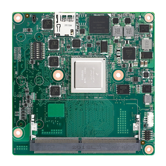
Page 12: Board Photo
Board Photo Block Diagram 16... -
Page 13: Pin Definition
Pin definition Connector Rows A and B Pin# Type 7 Description ROM-8720 Pin# Type 7 Description ROM-8720 Difference Difference GND(FIXED) GND(FIXED) GBE0_MDI3- GBE0_ACT# GBE0_MDI3+ LPC_FRAME#/ESPI_CS0# GBE0_LINK100# LPC_AD0/ESPI_CS0 GBE0_LINK1000# LPC_AD1/ESPI_CS1 GBE0_MDI2- LPC_AD2/ESPI_CS2 GBE0_MDI2+ LPC_AD3/ESPI_CS3 GBE0_LINK# LPC_DRQ0#/ESPI_ALERT0# GBE0_MDI1- LPC_DRQ1#/ESPI_ALERT1# GBE0_MDI1+ LPC_CLK/ESPI_CK GND(FIXED) - Page 14 Pin# Type 7 Description ROM-8720 Pin# Type 7 Description ROM-8720 Difference Difference RSVD I2C_CK BIOS_DIS0#/ESPI_SAFS I2C_DAT THRMTRIP# THRM# PCIE_TX13+ PCIE_RX13+ PCIE_TX13- PCIE_RX13- PCIE_TX12+ PCIE_RX12+ PCIE_TX12- PCIE_RX12- GND(FIXED) GND(FIXED) USB2- USB3- USB2+ USB3+ USB_2_3_OC# USB_0_1_OC# USB0- USB1- USB0+ USB1+ VCC_RTC ESPI_EN#...
- Page 15 Pin# Type 7 Description ROM-8720 Pin# Type 7 Description ROM-8720 Difference Difference PCIE_TX0+ PCIE_RX0+ PCIE_TX0- PCIE_RX0- GND(FIXED) GND(FIXED) PCIE_TX8+ PCIE_RX8+ PCIE_TX8- PCIE_RX8- PCIE_TX9+ PCIE_RX9+ PCIE_TX9- PCIE_RX9- PCIE_TX10+ PCIE_RX10+ PCIE_TX10- PCIE_RX10- GND(FIXED) GND(FIXED) PCIE_TX11+ PCIE_RX11+ PCIE_TX11- PCIE_RX11- NCSI_TX_EN VCC_5V_SBY GPI3 VCC_5V_SBY...
- Page 16 Pin# Type 7 Description ROM-8720 Pin# Type 7 Description ROM-8720 Difference Difference A103 LID# B103 SLEEP# A104 VCC_12V B104 VCC_12V A105 VCC_12V B105 VCC_12V A106 VCC_12V B106 VCC_12V A107 VCC_12V B107 VCC_12V A108 VCC_12V B108 VCC_12V A109 VCC_12V B109 VCC_12V...
- Page 17 Pin# Type 7 Description ROM-8720 Pin# Type 7 Description ROM-8720 Difference Difference GND(FIXED) GND(FIXED) USB_SSRX0- USB_SSTX0- USB_SSRX0+ USB_SSTX0+ USB_SSRX1- USB_SSTX1- USB_SSRX1+ USB_SSTX1+ USB_SSRX2- USB_SSTX2- USB_SSRX2+ USB_SSTX2+ GND(FIXED) GND(FIXED) USB_SSRX3- USB_SSTX3- USB_SSRX3+ USB_SSTX3+ 10G_PHY_MDC_SCL3 10G_PHY_MDIO_SDA3 10G_PHY_MDC_SCL2 10G_PHY_MDIO_SCL2 10G_SDP2 10G_SDP3 PCIE_RX6+ PCIE_TX6+...
- Page 18 Pin# Type 7 Description ROM-8720 Pin# Type 7 Description ROM-8720 Difference Difference 10G_LED_SCL RSVD 10G_SFP_SDA1 10G_SFP_SCL1 10G_SFP_SDA0 10G_SFP_SCL0 10G_SDP0 10G_SDP1 GND(FIXED) GND(FIXED) 10G_KR_RX1+ 10G_KR_TX1+ 10G_KR_RX1- 10G_KR_TX1- 10G_PHY_MDC_SCL1 10G_PHY_MDIO_SDA1 10G_PHY_MDC_SCL0 10G_PHY_MDIO_SDA0 10G_INT0 10G_INT1 10G_KR_RX0+ 10G_KR_TX0+ 10G_KR_RX0- 10G_KR_TX0- GND(FIXED) GND(FIXED) PCIE_RX16+ GBE1_MDI1+...
- Page 19 Pin# Type 7 Description ROM-8720 Pin# Type 7 Description ROM-8720 Difference Difference GBE2_LINK1000# GBE1_SDP PCIE_RX22- PCIE_TX22- GBE1_ACT# PCIE_RX23+ PCIE_TX23+ PCIE_RX23- PCIE_TX23- RSVD RSVD PCIE_RX24+ GBE3_MDI1+ PCIE_TX24+ GBE3_MDI0+ PCIE_RX24- GBE3_MDI1- PCIE_TX24- GBE3_MDI0- GND(FIXED) GND(FIXED) PCIE_RX25+ GBE3_MDI3+ PCIE_TX25+ GBE3_MDI2+ PCIE_RX25- GBE3_MDI3- PCIE_TX25-...
- Page 20 Pin# Type 7 Description ROM-8720 Pin# Type 7 Description ROM-8720 Difference Difference C107 VCC_12V D107 VCC_12V C108 VCC_12V D108 VCC_12V C109 VCC_12V D109 VCC_12V C110 GND(FIXED) D110 GND(FIXED) 23...
-
Page 21: Quick Start Of Rom-8720
2.4.2 Debug Port Settings ROM-8720 can communicate with a host server by using serial cables. Common serial communication programs such as HyperTerminal, Tera Term or PuTTY can be used in this case. The example below describes the serial terminal setup using HyperTerminal on a Windows host: 1. -
Page 22: Chapter 3 Software Functionality
Chapter Software Functionality This chapter details the software programs on the ROM-8720 plat- form. -
Page 23: Test Tools
Ubuntu 18.04 LTS. The purpose of this chapter is to introduce users to software configuration for ROM- 8720 to enable efficient application(s) development. "For detailed operation, please refer toUbuntu BSP User Guide for ROM-8720 form Wiki page: http://ess-wiki.advantech.com.tw/view/Linux_BSP_build_User_Guide_(LSDK20.12) 3.1.1 PCIE Test ◼... - Page 24 3.1.6 eMMC $ dd if=/dev/urandom of=/tmp/data bs=1 count=$SIZE &>/dev/null # Do backup $ dd if=${EMMC_DEV} of=/tmp/dataX bs=1 count=$SIZE skip=4096 &>/dev/null # Write bytes data $ dd if=/tmp/data of=${EMMC_DEV} bs=1 seek=4096 &>/dev/null # Reading & Comparing $ dd if=${EMMC_DEV} of=/tmp/data_r bs=1 count=$SIZE skip=4096 &>/dev/null $ diff /tmp/data /tmp/data_r 3.1.7 $ dd if=/dev/urandom of=/tmp/data bs=1 count=$SIZE &>/dev/null...
- Page 25 $ dhclient -I ${NET_INTF} $ iperf -c 192.168.0.2 -t 60 -i 10 3.1.10 10GBase-KR Test Plug ROM-EG60 to “OCP module connector” of SOM-DB5920 $ dhclient -I ${TG_INTF} $ iperf -c 192.168.0.2 -t 60 -i 10 3.1.11 GPIO Test $ echo ${PIN_NO} > /sys/class/gpio/export $ echo out >...
- Page 26 Chapter System Recovery This chapter introduces how to recover Ubuntu operating system if it is damaged accidentally.
-
Page 27: Chapter 4 System Recovery
System Recovery This section provides detail procedures of restoring the eMMC image. If you destroy the onboard flash image by accident, you can recover a system following these steps. Boot mode selection of ROM-8720 with “SW1” switch Switch item Settings... - Page 28 $ run bootcmd_usb0 12. Burn image to eMMC $ /usr/bin/flash_emmc.sh $ sync 13. Reboot by MMC mode (End)
-
Page 29: Chapter 5 Advantech Services
Chapter Advantech Services This chapter introduces Advantech design in serviceability, technical support and warranty policy for ROM- 8720 evaluation kit. -
Page 30: Contact Information
Contact Information Below is the contact information for Advantech customer service Region/Country Contact Information America 1-888-576-9688 Brazil 0800-770-5355 Mexico 01-800-467-2415 Europe (Toll Free) 00800-2426-8080 Singapore & SAP 65-64421000 Malaysia 1800-88-1809 Australia (Toll Free) 1300-308-531 800-810-0345 China (Toll Free) 800-810-8389 Sales@advantech.com.cn... -
Page 31: Technical Support And Assistance
Technical Support and Assistance For more information about this and other Advantech products, please visit our web- site at: http://www.advantech.com/ http://www.advantech.com/ePlatform/ For technical support and service, please visit our support website at: <http://support.advantech.com.tw/support/> Visit the Advantech web site at www.advantech.com/support where you can find the latest information about the product. - Page 32 No part of this publication may be reproduced in any form or by any means, electronic, photocopying, recording or otherwise, without prior written permis- sion of the publisher. All brand and product names are trademarks or registered trademarks of their respective companies. © Advantech Co., Ltd. 2022...
Need help?
Do you have a question about the ROM-8720 and is the answer not in the manual?
Questions and answers