Table of Contents
Advertisement
Quick Links
Advertisement
Table of Contents

Related Manuals for Prosense DPX Series


Summary of Contents for Prosense DPX Series
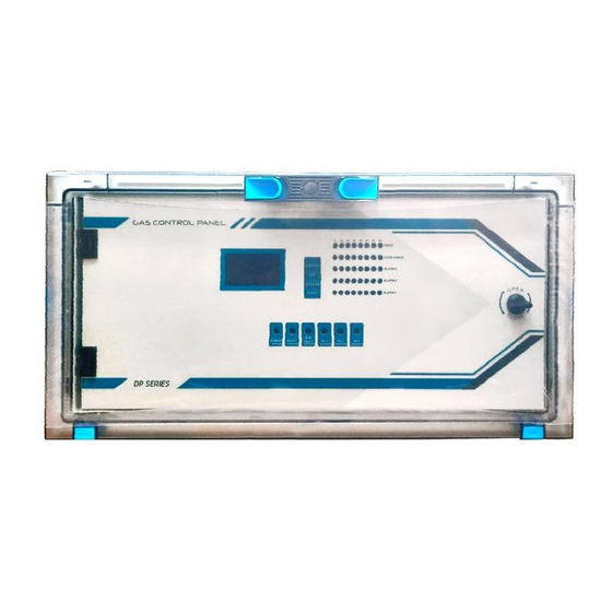
- Page 1 DPX Series Gas Control Panel User Manual DPX (4 / 8 32 / 64 / 128) Prosense Teknoloji San. Ltd. Şti. Cumhuriyet Mah. Mermer sok. No:16 34876 Kartal/İstanbul Tel: (90) 216 306 77 88 Faks: (90)216 473 81 29 www.prosense.com.tr...
- Page 2 Otherwise, it could fail to perform as designed and persons who rely on this product for their safety could suffer severe personal injury or death. The warranties made by Prosense with respect to this product are voided if the product is not installed, used and serviced in accordance with the instructions in this user guide.
-
Page 3: Table Of Contents
Contents Introduction ............................. 5 Technical Specifications........................6 Panel Dimensions ..........................7 Installation ............................8 Connections ........................... 11 MODBUS and Siren Outputs: ....................12 Analogue Channel Inputs: ..................... 13 Relay Outputs ........................14 MODBUS Channel Inputs: ...................... 16 Power Inputs: ........................18 5.5.1 Main Power Connection .................... - Page 4 What to Do In Case Of Alarm ....................46 Failure Codes: ........................47 Declaration ............................ 49 Appendix-A – Prosense Gas No Index ................... 50 Warranty statement ........................52 10.1 Exclusions ..........................52 10.2 Warranty Limitation and Exclusion ..................52 10.3 Limitation of Liability ......................
-
Page 5: Introduction
DPX Series Gas Control Panel has 128x64 OLED screen on the front panel to show status of each detector. This screen and menu keys allow user to set correct properties for each detector like gas concentrations by gas type, measurement type, measurement range and alarm levels. -
Page 6: Technical Specifications
2 Technical Specifications Power Source 220VAC Power Consumption 27VDC/250mA - 6.75W max. (without connected detectors) DPX4 : 4 x Analogue input DPX8 : 8 x Analogue input Inputs DPX32 : 2 x MODBUS input (16 + 16) + 8 x Analogue input DPX64 : 2 x MODBUS input (32 + 32) + 8 x Analogue input DPX128 : 2 x MODBUS input (64 + 64) + 8 x Analogue input FAULT, ALARM1, ALARM2, ALARM3, OVERRANGE (optional programmable... -
Page 7: Panel Dimensions
3 Panel Dimensions Panel dimensions are different for DPX4 and other models. DPX4 panel dimensions are explained in Diagram-2: Diagram 2: Dimensions (mm) DPX8, DPX32, DPX64, DPX128 Panel dimensions are explained in Diagram 3: Diagram 3: Dimensions (mm) PRS-UM-DP-X-EN-Rev1.0-17.11.2021... -
Page 8: Installation
4 Installation The DPX Series Gas Control Panel should never be placed in an explosive atmosphere and should be readily accessible. It is necessary to drill holes for cable glands either on the top or bottom of the control unit, depending on which side the electric cables are running in. - Page 9 IP66 rate cable gland to assure the box ingress protection is not compromised. The panel box is modular and can be used with different assemblies. Prosense recommends having cable entries from the lower side. Electronic board is located in the front cover of the panel.
- Page 10 Plastic screws Plastic screws Diagram 6: Panel cover plastic screw Backup battery connectors and fuse Wall mounting hole Power supply N L G V- V+ Space for backup batteries Wall mounting hole Wall mounting hole Main power entry and fuse Power supply output adjustment switch Diagram 7: Panel body PRS-UM-DP-X-EN-Rev1.0-17.11.2021...
-
Page 11: Connections
5 Connections DPX Series Gas Control Panel connections must be done on main board. The main building blocks of the panel PCB are pointed with letters on picture. Their meaning and details are as follows: MODBUS and Siren Outputs Analogue Channel Inputs... -
Page 12: Modbus And Siren Outputs
5.1 MODBUS and Siren Outputs: DPX Series Gas Control Panel provides RS485 MODBUS interface to communicate external devices or computers. Prosense Panel Monitor Software can be used to configure panel parameters and monitor the panel status through MODBUS communication. This Interface is marked as RS485-3 on main PCB board. -
Page 13: Analogue Channel Inputs
5.2 Analogue Channel Inputs: DPX series Gas Control Panel has analogue channel inputs to connect detectors via using 4-20mA output. DPX4 Panel has 4 analogue channel inputs while DPX8 Panel will have 8 analogue channel inputs. DP8 Panel 8x Inputs:... -
Page 14: Relay Outputs
(20 to 13 AWG) conductors can give better results. Ensure the cable gland is installed correctly and fully tightened. 5.3 Relay Outputs DPX Series Gas Control Panel without any optional relay modules has five relay outputs which are FAULT, ALARM1, ALARM2, ALARM3 and OVERRANGE. The connection ports are marked on mainboard. - Page 15 The relay output pin positions shown below: Normally Open (NO) Normally Close (NC) Table 6: Relay output pin positions Fault Relay is always works in Normally Close mode and there is no selection pin for fault relay (Relay-1). If panel lost power user will always get switching contact from fault relay. Relay numbers and related events are defined as below: Relay No Event...
-
Page 16: Modbus Channel Inputs
V- to supply detector power on Line 3 Table 8: MODBUS Channel pin definitions DPX Series Gas Control Panel is a master device in the MODBUS Network and it initiates the communication with a “query” to “Slave” devices which are detectors. The “Slave “ which is constantly monitoring the network for “Queries”... - Page 17 < 50pF/m and nominal impedance should be 120 Ohms. The V+, V- ports and A, B ports are located different sockets in DPX Series Gas Control Panel main board. These ports are also formed in different sockets on Prosense detectors. The connections should be done with care to do not mix power and RS485 ports.
-
Page 18: Power Inputs
Daisy Chain Connection - Correct Diagram 16: MODBUS detector connections Each detector connected to same DPX Series Gas Control Panel should have unique address. Detectors having same address would not be recognised by control panel. The last detector at the RS485 serial line should have the end of line resistor to enable the total communication line. -
Page 19: Main Power Connection
There is no need to remove the power and grounding connections from panel mainboard. But in case of any service action pins and connection locations must be controlled according to labels printed on mainboard. 5.5.1 Main Power Connection The Panel has internal switching power supply to mains connection (220VAC). This connection must be made three-wire 1.5mm cross section cable to the main supply terminal entries and fixed by using cable fastener on the terminal. -
Page 20: Fuses
5.6 Fuses DPX series Gas Control Panel has six fuses on main board to keep connected devices and panel safe. Their names and details are given below: Fuse Rating Usage Main power protection VOUT A Protection VOUT B Protection Analog channel power protection... - Page 21 Analogue module also provides relay output for the connected detectors. The relays work for both detectors. The Ports and their usage are given in below table: Block Port Usage Power input port V+ 24VDC PWR IN Power input port GND RS485 MODBUS A pin to connect DPX panel RS485 IN RS485 MODBUS B pin to connect DPX panel...
-
Page 22: Indicators
Table 16: Panel buttons and functions Diagram 19: Front panel signs LCD and LEDs DPX Series Gas Control Panel has 40 LEDs numbered from Z1 to Z8 nearby LCD panel. Each zone has a LED indicator for fault, overrange, Alarm-1, Alarm-2, Alarm-3 status. These LEDs will be activated in case of fault, alarm or overrange to identify which detector zone is raising the status. -
Page 23: Display
6.1 Display: DPX Series Gas Control Panel has an OLED display to show overall panel status event summary and detector details. Panel Status screen provides a summary report about panel and related components: Panel Status : OK Power Main : OK... - Page 24 Alarm Cntr. : 2 Z1CH01 Z2D004 METHANE OVRNG Panel also provides detailed view of each detector. The measurement level will be reported as alphanumeric value and also in a bar format. Detector will be reported as zone and channel information if detector is connected to analogue input channel. The example below shows Z1/CH1 meaning that detector is connected to analogue channel number 1 and assigned to Zone1.
-
Page 25: Special States
6.2 Special States Panel can recognize any special state in 2 minutes. Special States that can be recognized by the panel are: • Warm up • Fault • Alarm (Alarm-1, Alarm-2, Alarm-3) • Overrange Below messages will be shown on display and visual indicators will be activated: Status Screen Output LED Output... -
Page 26: Fault Status
6.4 Fault Status: The panel reports FAULT status in below cases: • In case any of the detector connections lost • In case any of the detector measurement level goes below minimum level • In case any of the detector goes in to fault state •... -
Page 27: Alarm Status
Z1/CH1 ALARM METHANE OVRNG >100 %LEL 0V 0C 27 MAR 16:58 Diagram 10: Overrange status display Panel needs user intervention to clear Overrange that can be reset via menu step “Reset”. If the detector is connected through modbus channels, panel can send reset command to detector and clear the status if actual measurement level decreases. -
Page 28: Programming
7 Programming The panel needs configuration update according to site requirements and connected detectors. User should define connected detectors, define zones, adjust the alarm levels for each detector and adjust relay parameters. Each detector should be defined independently to related detectors measurement unit and scale as well as alarm levels. These adjustments can be done via using the keys nearby the screen. -
Page 29: Panel Configuration
7.1.1 Setting Up Network Parameters: DPX Series Gas Control Panel provides MODBUS and Ethernet connectivity. Panel can directly connected to a device that can understand MODBUS communication. RS485-3 port is programmed to provide MODBUS output from panel to a computer or a similar device. -
Page 30: Setting Up Passwords
“Successful” message to confirm values are recorded. 7.1.2 Setting Up Passwords: DPX Series Gas Control Panel provides two level security as L1 and L2. Level-1 (L1) security password is used to enable menu access. Level-2 (L2) security password is used to enable detector configuration menu. -
Page 31: Setting Up Date And Time
7.1.3 Setting Up Date and Time: DPX Series Gas Control Panel keeps date and time information. It has an internal battery and even main power lost it can keep event logs safe. Select “3. Date and Time” option from Configuration menu to adjust date and time. Panel program will provide current date and... -
Page 32: Setting Up Battery
7.1.5 Setting Up Battery: DPX Series Gas Control Panel can operate with batteries in case of power lost. To enable battery operation user should set batteries via using Configuration menu option “5. Battery. Panel program will ask number of batteries: Num. - Page 33 2- Menu options will be listed: 1. Detector Settings 2. Relay Settings 3. Configuration 4. Test 5. Information 6. Reset Select “1. Detector Settings” and press MENU button. Panel software will request L2 password: PASSWORD L2 The default L2 password is 2222. It is strongly recommended to change the password after first login.
- Page 34 Zone No is a logical definiton that user can group detector depending of the specific parameters such as location, gas type etc. DPX series panels can have up to 8 zones. If zone set to 0 , it disables the related detector.
-
Page 35: Analogue Detector Alarm Settings
Range is measurement range of the detector. It can be defined as 0-100% LEL, 0-100%VOL, 0-10000PPM, 0-10000PPB. Once all set press MENU button and panel will record the given values and show a confirmation with “Successful” message. 7.2.2 Analogue Detector Alarm Settings: Alarm levels for the analogue channel detectors must be defined at panel side. -
Page 36: 4-20Ma Settings
Once all set panel program will perform sanity check adn print “Successful” messages to confirm recording operation. 7.2.3 4-20mA Settings: It is recommended to adjust 4-20mA settings to define fault, warm-up, overrange etc. signal levels for each channel. When you select “3. 4-20mA Settings” panel will display these options: Channel Fault... -
Page 37: Modbus Detector Configuration
7.2.4 MODBUS Detector Configuration: DPX Series Gas Control Panel can read detector configuration details through MODBUS communication from Prosense Gas Detectors. To start communication between detector and panel detector must be set on through panel settings. User should set detector Modbus address on detector side and set detector ON panel side while detector is connected and working. -
Page 38: Modbus Detector Alarm Settings
(0) detector will be disabled even it is connected to panel. 7.2.5 MODBUS Detector Alarm Settings: DPX Series Gas Control Panel can able to read status and parameter information directly from a Prosense Gas detector. To adjust alarm parameters user should select “1.Alarm Settings”... -
Page 39: Modbus Detector Calibration
MODBUS connected detectors will be same all the time. 7.2.6 MODBUS Detector Calibration: DPX Series Gas Control Panel can initiate calibration operation for detector connected to MODBUS channels. This operation does not work for detectors connected to analogue channels. - Page 40 Select “Set Span” for span calibration: Detector : 001 Operation : Set Span Once calibration operation is started panel will switch to the single detector display mode: Z1/CH1 CALIBR METHANE %LEL 0V 0C 27 MAR 16:58 The counter will be displayed at right top side of the display to monitor calibration progress. The display will be updated with current status of the detector once the calibration operation completed: Z1/CH1...
-
Page 41: Relay Settings
7.3 Relay Settings: DPX Series Control Panel has five relay outputs. Relay numbers and related events are defined as below: Relay No Event Monitoring area Assignment Relay-1 FAULT All Zones and Panel itself No alteration Relay-2 ALARM-1 All Zones No alteration... -
Page 42: Test Options
7.4 Test Options: DPX Series Control Panel provides artificial testing option to user to control connections and event generation scenarios without using real gas. To run tests select “4.Test” option from main menu: 1. -
Page 43: Information
Relay :1 : De-energized 7.5 Information: DPX Series Control Panel keeps event records. To see recorded events select “5. Information” option from main menu: 1. Detector Settings 2. Relay Settings 3. Configuration 4. - Page 44 Event logs will display fault and alarm events recorded by panel. Log [001] Z:3 D:6 10 MAR 16:43 ALARM AL3 Use UP and DOWN buttons to navigate recorded events by time. “2. Control Panel” option provides detail about control panel details: Model : DP32 Serial No...
-
Page 45: Resetting Alarms
7.6 Resetting Alarms: The DPX Series Gas Control Panel raises audible and visual alarms when detected an alarm condition. User can stop internal buzzer and external Siren via pressing the MENU button for 5 minutes. If the condition is same panel will again raise the alerts after 5 minutes. User can initiate reset status via using the panel. -
Page 46: What To Do In Case Of Alarm
7.7 What to Do In Case Of Alarm Refer to the mandatory safety procedures (gas alarm) set forth by your safety manager. Recommendations: Keep calm and follow these instructions: 1. Put out all naked flames (including cigarettes, pipes, etc.) 2. Turn off all gas appliances. 3. -
Page 47: Failure Codes
7.8 Failure Codes: DPX Series Gas Control Panel provides overall status screen provides error codes when a failure is detected such as: Panel Status : OK Power Main : FAULT 20 Line Power : OK Battery : FAULT 41 RTC Batt. - Page 48 Fault Code Fault Name Details -1 NET_TIMEOUT Timeout reached during a blocking operation -2 NET_ERROR_WOULD_BLOCK no data is available but call is non-blocking -3 NET_ERROR_UNSUPPORTED unsupported functionality -4 NET_ERROR_PARAMETER invalid parameter/configuration -5 NET_ERROR_NO_CONNECTION not connected to a network -6 NET_ERROR_INVALID_SOCKET socket invalid -7 NET_ERROR_NO_ADDRESS IP address is not known...
-
Page 49: Declaration
8 Declaration PRS-UM-DP-X-EN-Rev1.0-17.11.2021... -
Page 50: Appendix-A - Prosense Gas No Index
9 Appendix-A – Prosense Gas No Index Gas No Gas Name 30 LPG 31 Methane 32 Petrol vapour 33 n Butane 34 Propane 35 Hexane 36 Hydrogen 37 Pentane 38 Toluene 39 Methanol 40 Heptane 41 Octane 42 Ethanol 43 Iso propanol... - Page 51 77 Nonane 78 Acetaldehyde 79 Hydrogen Chloride 80 TVOC 81 VOC 82 Ozone 83 HF 84 Phospine 85 Isobutylene 86 Silane 87 Diborane 88 Arsine 89 Germane 90 Air Quality 91 A2L Refrigerant Gas Table 23: Prosense Gas Number Index PRS-UM-DP-X-EN-Rev1.0-17.11.2021...
-
Page 52: Warranty Statement
Istanbul TURKEY, in a package equal to or in the original container accompanied by a detailed description of any issue. Prosense reserves the right to charge for any site attendance where any fault is not found with the equipment in case return of goods is not practicable. Prosense shall not be liable for any loss or damage whatsoever or howsoever occasioned which may be a direct or indirect result of the use or operation of the Contract Goods by the Buyer or any Party.
Need help?
Do you have a question about the DPX Series and is the answer not in the manual?
Questions and answers