Table of Contents

Related Manuals for Prosense PPS Manager


Summary of Contents for Prosense PPS Manager
- Page 1 PROSENSE PPS Manager Gas Control Panel User Manual Prosense Teknoloji San. Ltd. Şti. Cumhuriyet Mah. Mermer sok. No:16 Kartal İstanbul Tel: (90) 216 306 77 88 Faks: (90)216 473 81 29 www.prosense.com.tr PRS-UM-PPSM-EN-Rev.03-10.04.2020...
- Page 2 Properly installed panel can be used without any problem and covered under Prosense warranty. The warranties made by Prosense with respect to this product are voided if the product is not installed, used and serviced in accordance with the instructions in this user manual.
-
Page 3: Table Of Contents
CONTENTS 1.INTRODUCTION ............................ 4 Technical Specifications....................... 4 1.2 Panel Dimensions ..........................5 2. INSTALLATION............................. 5 3. FUNCTIONS AND DETAILS ........................7 3.1 LCD Screen: ............................8 4. MAIN BOARD AND CONNECTIONS ...................... 9 4.1 Main Board Details: ........................... 9 4.2 Backup Battery Connection ......................10 4.3 Main Power Connection ........................ -
Page 4: Introduction
PPM level, the control panel is able to shut off a gas valve, cut off power and turn on an alarm via activating relays. Prosense PPS Control Panel can have up to 4 zone modules that each can monitor up to 32 detectors. A fully configured PPS Panel can handle managing 128 detectors. PPS Panel can be configured depending on detectors used in each project with one, two, three or four zone modules. -
Page 5: Panel Dimensions
1.2 Panel Dimensions Panel dimensions are explained in Diagram 1: Diagram 1: Dimensions (mm) 2. INSTALLATION The PPS Control Panel box should never be placed in an explosive atmosphere and should be readily accessible. It is necessary to drill holes for cable glands either on the top or bottom of the control unit, depending on which side the electric cables are running in. - Page 6 IP66 rate cable gland to assure the box ingress protection is not compromised. The panel box is modular and can be used with different assemblies. Prosense recommends having cable entries from the lower side. Electronic board is located in the front cover of the panel. The power supply is located at the back of panel box.
-
Page 7: Functions And Details
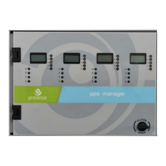
3. FUNCTIONS AND DETAILS The front panel has the following LEDs for each zone as shown in Diagram 4: Sign Meaning Panel is in operation FAN1 FAN1 relay status FAN2 FAN2 relay status ALARM ALARM status FAULT Fault condition in at least one of the zone module Table 2 : Front panel signs and meanings There are four buttons near by LCD screen to perform configuration and display the detector details. -
Page 8: Lcd Screen
Press to open Locker Diagram 5: Front cover If panel ordered with keys a key needed to open plastic cover. In order to make panel connection, you need to open the front cover using the key at right bottom side of front panel. The key works clockwise and vice versa. -
Page 9: Main Board And Connections
4. MAIN BOARD AND CONNECTIONS 4.1 Main Board Details: PPS Control panel has one power module and main power connection from power supply to control panel made on this board. This board provides power to zone modules. Connections to Zone modules Main power input Fuse Alarm relay... -
Page 10: Backup Battery Connection
V+ A B V- Alarm FAN2 FAN1 Detector connections Relay outputs Diagram 9: Control panel zone module board 4.2 Backup Battery Connection To contiue operation in case of main power failure two backup batteries (12V 7Ah) must be serially connected to the system. Take extra care to use correct poles while connecting the batteries. The cables or main board can be damaged in case of mixing pins or making short circuits. -
Page 11: Main Power Connection
The V+, V- ports and A,B ports are located on same socket in PPS panel zone module. These ports are formed together on Prosense PPS series detectors on detector main board. The connections should be done with care to do not mix power and RS485 ports. All detectors will be connected through one cable via hopping one detector to another till the last detector on the line. - Page 12 Otherwise control panel may not communicate to all, some or none of the detectors. The end of line resistor controlled by end of line pins located on Prosense PPS series detectors and can be enabled via putting the jumper on end of line pins. Details are given in section 4.5.
-
Page 13: Pps Series Detectors Connections
4.5 PPS Series Detectors Connections Prosense PPS series detectors has onboard RS485 Modbus serial communication module. The board has 4 ports thus the detector connection should be made by 4 wire that 2 for power and 2 for RS485. The total lenght of the connection line should not exceed 1000 meters. - Page 14 Diagram 14: RS485 Modbus serial communication address and switch position The last detector in the chain should have 120 Ohms RS485 termination resistor. The resistor is already implemented on the board by default but not activated. User should activate the termination resistor via using the termination pin once the installation completed: End of Line jumper enabled Diagram 15: RS485 Modbus serial communication module end of line jumper...
-
Page 15: Relay Outputs
4.5 Relay Outputs PPS panel has two relays which are fault and alarm on main power module. Fault: This relay will be activated when any of the zone modules in the system raise fault status. Alarm: This relay will be activated when any of the zone modules in the system will exceed the programmed alarm level. -
Page 16: Automatic Test
5.2 LED Test Prosense PPS Manager has special function to test LEDs on front panel at any time. Press T button to initiate test operation. Panel will activate all LEDs for moment and turn off all of them except on LED as it is always blinking. -
Page 17: Set Fan2 Relay Level
Sel Gas Gas type can be changed via pressing up and down arrow buttons. There are three gas type supported by PPS Manager which are CO, NO2, LPG. Once decided press Menu button to continue. It will show the current level: Ext1 Lv: Alarm level can be increased or decreased via pressing up and down arrow buttons. -
Page 18: Set Alarm Relay Level
Sel Gas Gas type can be changed via pressing up and down arrow buttons. There are three gas type supported by PPS Manager which are CO, NO2, LPG. Once decided press Menu button to continue. It will show the current level: Alrm Lv: Alarm level can be increased or decreased via pressing up and down arrow buttons. -
Page 19: Set Gas Type
Once decided use T button to return back to main menu or press again to exit from menu. 6.5 Set Gas Type: PPS Manager can work together simultaneously three different gas type which are CO, NO2 and LPG. Althugh PPS Manager can automatically recognize the connected detectors, it asks user to confirm gas type. -
Page 20: Set Language
6.6 Set Language: PPS Manager currently supports two languages which are English and Turkish. User can change the language via seventh menu item “Language”. Press menu button and use up and down arrow buttons to reach “Language“... -
Page 21: Scan Detectors
6.7 Scan Detectors: In case any detectors added, replaced or changed on PPS Manager, Scanning should be initiate to allow panel recognize the detectors. This can be done via eight item on the menu. Press menu button and use up and down arrow buttons to reach “Scan Det“ menu item: Scan Det Press menu button again to start scanning. -
Page 22: Alarm Status
There are 4 independent LEDs for each zone module as fault, alarm, fan1 and fan2. Depending of the alarm activation type PPS Manager activate Fan1, Fan2 or Alarm relays and activate related LEDs on the front panel. As it is designed to work for parking areas, fan1 will be activated to start ventilation when average or any one of the detectors gas reading reaches the defined level. -
Page 23: Fault Codes
If the alarm stops and the reason for the alarm is identified and resolved (e.g. a kitchen burner lit off but in the open position) the gas supply may be re-opened after checking that all the gas appliances are off. 8. -
Page 24: Declaration
Declaration PRS-UM-PPSM-EN-Rev.03-10.04.2020... -
Page 25: Warranty Statement
Prosense Technology shall not be liable for any loss or damage whatsoever or howsoever occasioned which may be a direct or indirect result of the use or operation of the Contract Goods by the Buyer or any Party.
Need help?
Do you have a question about the PPS Manager and is the answer not in the manual?
Questions and answers