Table of Contents

Related Manuals for Prosense S-DP32


Summary of Contents for Prosense S-DP32
- Page 1 PROSENSE S-DP32 Gas Control Panel User Manual Prosense Teknoloji San. Ltd. Şti. Yukarı Mah. Harman sok. No:42 Kartal İstanbul Tel: (90) 216 306 77 88 Faks: (90)216 473 81 29 www.prosense.com.tr PRS-UM-DP32-EN-Rev.02-05.2019...
- Page 2 Otherwise, it could fail to perform as designed and persons who rely on this product for their safety could suffer severe personal injury or death. The warranties made by Prosense with respect to this product are voided if the product is not installed, used and serviced in accordance with the instructions in this user guide.
-
Page 3: Table Of Contents
Main Board Details: .......................... 12 Backup Battery Connection ......................13 Main Power Connection ........................13 Detectors Connections ........................14 Prosense RS485 Serial Communication Module for Prosense Detectors ......... 15 Relay Outputs ........................... 16 AUX Relay Output ..........................17 First Run ............................... 17 Automatic Test .......................... -
Page 4: Introduction
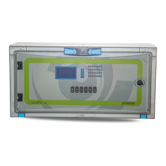
S-DP32 has 128x64 LCD screen on the front panel to show status of each detector. This LCD screen and menu keys allow user to set correct properties for each detector like gas concentrations by gas type, measurement unit, and range and alarm levels. -
Page 5: Technical Specifications
Technical Specifications Power Source 220VAC ±10% 50/60 Hz Power Consumption 27VDC/250mA - 6.75W max. (without connected detectors) Inputs (Internal) 1 serial input that can communicate to 32 detectors via RS485 Relay outputs FAULT, ALARM1, ALARM2, AUX Contact ratings 3A, 24VDC or 3A 120VAC Display Graphic LCD (128x64) LED indicators... -
Page 6: Panel Dimensions
Installation Diagram 2: Dimensions (mm) The S-DP32 control panel box should never be placed in an explosive atmosphere and should be readily accessible. It is necessary to drill holes for cable glands either on the top or bottom of the control unit, depending on which side the electric cables are running in. - Page 7 The key works clockwise and vice versa. Diagram 5: Locker. S-DP32 panel has 6 plastic screws keeping panel door in place in front of panel. Use a flat screwdriver to lose them and remove the panel door assembly. Please take care and remove the connectors on the electronic card while removing the cover.
- Page 8 Plastic screws Plastic screws Diagram 6: Panel cover plastic screw Backup battery connectors and fuse Wall mounting hole Wall mounting hole Power supply Power supply output adjustment switch N L G V- V+ Space for backup batteries Wall mounting hole Wall mounting hole Main power entry and fuse Power supply LED...
-
Page 9: Functions
Diagram 8: Front panel signs LCD and LEDs S-DP32 Panel has 32 LEDs numbered from1 to 32 nearby LCD panel. These LEDs will be activated in case of an alarm to show which detector is raising the alarm. If any of these LEDs are active it indicates the detector having that address has reached specified threshold level. -
Page 10: Lcd Screen
LCD Screen: LCD screen shows time details and status of each detector connected to channels as shown in Diagram 8. As The LCD screen can show 6 lines at same time there are up to six pages that you can move via UP and DOWN buttons: Diagram 9: LCD screen first page Note: Date and time information will be unavailable when RS485 module installed. -
Page 11: Alarm Status
Fault relay is energized and set to NC by default. User can monitor power status as it will be switched in case of total power loss. Alarm Status: The Panel will report Alarm status when gas level exceedes defined alarm levels on any of the detector channel. -
Page 12: Main Board And Connections
Main Board and Connections S-DP32 Control panel has one integrated main board. All components and connections are located on main board. Main Board Details: S-DP32 Control panel has all connections on main board. Relay module mounting holes LCD brightness adjustment potentiometer... -
Page 13: Backup Battery Connection
S-DP32 Panel has a buzzer on the main board to generate sound alarms. A digital input port provided on main board that should be 24VDC. To activate this input the AUX relay must be defined as Alarm-3 to work with digital input. -
Page 14: Detectors Connections
< 50pF/m and nominal impedance should be 120 Ohms. The V+, V- ports and A, B ports are located different sockets in S-DP32 main board. These ports are formed in same or different sockets on Prosense detector address modules. The connections should be done with care to do not mix power and RS485 ports. -
Page 15: Prosense Rs485 Serial Communication Module For Prosense Detectors
Otherwise control panel may not communicate to all, some or none of the detectors. The end of line resistor controlled by end of line pins located on address module of Prosense detectors and can be enabled via putting the jumper on end of line pins. -
Page 16: Relay Outputs
For more details please check detector user manuals. Relay Outputs S-DP32 panel has four relay outputs which are ALARM1, ALARM2, FAULT and AUX. Relay connection ports are located right under the relays. Alarm relays are operating in latched mode. Hence the panel will wait user intervention to clear alarm status even conditions returned to normal. -
Page 17: Aux Relay Output
First Run in 9th line on LCD as digital alarm. Panel manufacturer (Prosense) and model (S-DP32) will be seen on LCD screen following the power-up. All LEDs on the panel and sounder device will be activated for 3 seconds. The user can recognize any malfunctioning LED on panel at this period. -
Page 18: Programming
4. Detectr. Diagram 16: Menu structure S-DP32 control panel keeps data and time information to record alarm events in the internal log space. The alarm logs menu is not available when panel uses RS485 module to communicate to Prosense Panel Monitor software. -
Page 19: Setup Channel Parameters
3- Move desired Channel from the list via using UP and DOWN buttons and press MENU button to select channel. A new menu will display with below options: 4- S-DP32 panel automatically recognize the measurement unit and range while communicating the detector. Therefore these settings cannot be changed by user. To adjust alarm level settings select "Level Settings"... -
Page 20: Closing Unused Channels
MENU button to change status. It will be deactivated and shown like below: Once the temporarily outage has been resolved user should follow same steps and open the channel. S-DP32 panel will start communicating to the detector without power-off/power-on the control panel. PRS-UM-DP32-EN-Rev.02-05.2019... -
Page 21: Relay Assignment
Relay Assignment: The alarm relays work only in latched mode. Therefore, the relay will not be released and stay in active mode till manual intervention. Even after environment is cleaned following an alarm condition, the relay will stay active in latching mode. User should release them via pressing the EXIT button for 2 seconds. -
Page 22: What To Do In Case Of Alarm
What to Do In Case of Alarm There are 3 independent LEDs for each detector as fault, alarm and power LEDs. In addition to them there are two alarms, one fault, one power and one battery LED used to monitor overall panel status. -
Page 23: Controlling The Alarm Fault Functions
Controlling the Alarm Fault Functions PROBLEMS POSSIBLE CAUSES WHAT TO CHECK The display is not Main power source is Check the Main power connection Check the power supply. The green LED should be Bad power supply. Check fuses on main power connection and Blown fuse(s). -
Page 24: Warranty Statement
Prosense Technology's liability for any claims arising out of or related to this product will in no case exceed the order value. To the extent permitted by applicable law, these...
Need help?
Do you have a question about the S-DP32 and is the answer not in the manual?
Questions and answers