Table of Contents
Advertisement
Quick Links
Advertisement
Table of Contents
Troubleshooting

Related Manuals for Hardy Process Solutions HI 2160RC PLUS


Summary of Contents for Hardy Process Solutions HI 2160RC PLUS
- Page 1 HI 2160RC PLUS Rate Controller Operation and Installation Manual...
- Page 2 Table of Contents Table of Contents Table of Contents - - - - - - - - - - - - - - - - - - - - - - - - - - - - - - - - - - - - - - - i Table of Illustrations - - - - - - - - - - - - - - - - - - - - - - - - - - - - - - - - - - - - - - - I Chapter 1...
-
Page 3: Table Of Contents
Unpacking - - - - - - - - - - - - - - - - - - - - - - - - - - - - - - - - - - 3-1 Installing the HI 2160RC PLUS in a Panel- - - - - - - - - - - - - - - - - - - 3-2... - Page 4 Table of Contents PROFIBUS Interface Option (-B4) - - - - - - - - - - - - - - - - - - - - - - 4-11 Changing the RS-422 Converter Port Option (-B1) - - - - - - - - - - - - - - 4-11 Setting the Dip Switches - - - - - - - - - - - - - - - - - - - - - - - - - 4-11 Rear Panel Config.
- Page 5 HI 2160RC PLUS MANUAL Chapter 6 Setup - - - - - - - - - - - - - - - - - - - - - - - - - - - - - - - - - - - - 6-1 About Chapter 6 - - - - - - - - - - - - - - - - - - - - - - - - - - - - - - - 6-1 Display Menu Trees - - - - - - - - - - - - - - - - - - - - - - - - - - - 6-1 Display Menu Flow Chart with Standard Serial Port - - - - - - - - - - 6-1...
- Page 6 Table of Contents Restoring Data Saved in the Secure Memory Module - - - - - - - - - - - - - 6-39 Data Recall Procedures - - - - - - - - - - - - - - - - - - - - - - - - - 6-39 Setting the Control Out LO% and Control Out HI% - - - - - - - - - - - - - - 6-40 Setting the Control Out LO% - - - - - - - - - - - - - - - - - - - - - - - 6-40 Setting Control Out HI% - - - - - - - - - - - - - - - - - - - - - - - - - 6-43...
- Page 7 HI 2160RC PLUS MANUAL Application - - - - - - - - - - - - - - - - - - - - - - - - - - - - - - 8-25 Setup - - - - - - - - - - - - - - - - - - - - - - - - - - - - - - - - 8-25 Down Loading Rate Set Points Via Analog Signal for PLC's that are not Equipped with PROFIBUS or Allen Bradley Remote I/O - - - - - 8-26 Rate Exception Control - - - - - - - - - - - - - - - - - - - - - - - - - - - - 8-28...
- Page 8 Table of Illustrations Table of Illustrations CHAPTER 1 OVERVIEW - - - - - - - - - - - - - - - - - - - - - - - - - - - - - - - - - 1-1 PLUS FIG.
- Page 9 HI 2151/30WC MANUAL FIG. 4-7 REMOTE FUNCTION OPTION - - - - - - - - - - - - - - - - - - 4-7 FIG. 4-8 JUMPER SETTINGS FOR ANALOG INPUT PWA AND F1 FUSE - 4-9 FIG.
- Page 10 Table of Illustrations FIG. 6-27 SERIAL PORT #1 CONFIGURATION - - - - - - - - - - - - - - - 6-32 FIG. 6-28 SERIAL PORT #1 CONFIGURATION - - - - - - - - - - - - - - - 6-33 FIG.
- Page 11 HI 2151/30WC MANUAL CONFIGURATION - - - - - - - - - - - - - - - - - - - - - - - - 8-28 FIG. 8-29 SELECTING TEST MENU - - - - - - - - - - - - - - - - - - - - 8-30 FIG.
- Page 12 Hardy Process Solutions appreciates your business. Should you not understand any information in this manual or experience any problems with the product, please...
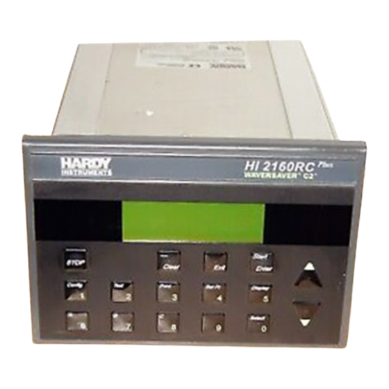
- Page 13 PLUS HI 2160RC MANUAL up or slow down the driver of the feeding device thereby achieving the desired flow rate. The user simply enters the flow parameters via the key touch pad (See Fig. 1-1) or standard bi-directional serial port or optional Interface and the HI 2160RC PLUS rate control algorithm auto-...
-
Page 14: Fig. 1-1 Hi 2160Rc Plus Rate Controller
Chapter 1 - Overview PLUS FIG. 1-1 HI 2160RC RATE CONTROLLER Capabilities Automatic Control Automatically corrects for variations in desired flow rates. Mode ® WAVERSAVER Ignores plant and process vibration for more accurate measurement of feed rates. Manual Control Use the up and down arrows to manually control the flow rate. Convert Mode to automatic mode when proper flow rate is achieved. - Page 15 PLUS HI 2160RC MANUAL takes only a few seconds. Does not require recalibration of the scale. Maximizes up time for the feed systems. Control Output Electrically and optically isolated, user selectable 0-20 mA, 4-20 mA, 0-5 VDC, or 0-10 VDC output. Front Panel 5"...
-
Page 16: Fig. 1-2 Model Code Breakdown
Chapter 1 - Overview H I 2 1 6 0 R C - P M - A 1 - B 1 - C 1 - D 1 - E 1 PM - PANEL MOUNT RM - REMOTE DISPLAY MOUNTING A1 - CONTROL OUTPUT 4-20 MILLIAMPS A2 - CONTROL OUTPUT 0-20 MILLIAMPS... -
Page 17: Fig. 1-3 Optional Expander Box (Non-Fm)
PLUS HI 2160RC MANUAL • Optional Expander Box (Non FM) (See Fig. 1-3) The dash number for the expander box is: -HI216EX If the expander box is configured for 240 VAC Opera- tion the dash number is: NOTE: Requires the -E1 option expander card to be installed in the main rate controller. FIG. - Page 18 Chapter 2 - Specifications CHAPTER 2 - SPECIFICATIONS About Chapter 2 Chapter 2 lists the specifications for the HI 2160RC PLUS rate controller. Specifications are listed for the standard instrument and for instruments fitted with optional equipment. The specifications listed are designed to assist in the installation, operation and troubleshooting of the instru- ment.
- Page 19 PLUS HI 2160RC MANUAL Output Display • Liquid Crystal Display (LCD) - 80 characters Specifications • Display Format: 4 line x 20 character full ASCII (5 x 7 dot matrix) • Display Increments: 1,2,5,10,20,50,100,200,500 counts selectable by keypad. Corresponding weight is dependent on decimal point location.
-
Page 20: Quad Option Expander Box - Basic Function
Expander Box - 3. Interfaces to the 2160 Rate Controller - TTL interfacing Basic Function (See between the HI 2160RC PLUS and the quad option box via Fig. 1-3) quad interface card, installed in the HI 2160RC PLUS option slot, and a 40 pin ribbon cable. - Page 21 PLUS HI 2160RC MANUAL • Either Output Linearity - 0.01% NOTE: With one (1) average selected. Response Time After Update 1 millisecond Isolation from Main Board 300 VAC or 450VDC Update Rate 50 milliseconds (20 times/second) The RS-232 to RS-422 Converter Board Option converts RS-232C RS-232 to RS-422 standard signals to RS-422 4 wire format signals.
- Page 22 Chapter 2 - Specifications NOTE: We recommend that the RS-422 cable shield connection be terminated to frame PLUS ground on the HI 2160RC rear panel.
- Page 23 PLUS HI 2160RC MANUAL...
-
Page 24: Chapter 3 Installation
Customer Support e-mail: hardysupport@hardysolutions.com Step 5. Record the model number and serial number of the Rate Con- troller. Store in a convenient, secure location for reference when contacting Hardy Process Solutions Customer Service Department or to buy parts or firmware upgrades. -
Page 25: Installing The Hi 2160Rc Plus In A Panel
PLUS HI 2160RC MANUAL Installing the HI 2160RC PLUS in a Panel Mechanical Installation Panel Cutout Specifications • Overall depth of the enclosure must be a minimum of 11.75" to Enclosure Size allow for the 2" clearance between the rear panel of the Requirements. -
Page 26: Fig. 3-2 1" Clearance Require Around Bezel
Chapter 3 - Installation Step 3. Gently slide the controller into the cutout in the enclosure. (See Fig. 3-4) Be sure to secure the controller with both hands when installing. 1.0” Bezel 1.0” 1” Clearance Requirement around bezel FIG. 3-2 1” CLEARANCE REQUIRE AROUND BEZEL 6.35"... -
Page 27: Fig. 3-4 Mounting Controller In Panel
PLUS HI 2160RC MANUAL Customer’s Panel FIG. 3-4 MOUNTING CONTROLLER IN PANEL Step 4. Slide the controller into the panel cutout until the NEMA 4 gasket is flush against the front panel of the enclosure. (See Figs. 3-5, 6, & 7) Compression Gasket Rear... -
Page 28: Fig. 3-6 Controller Flush To Front Panel/Front View
Chapter 3 - Installation FIG. 3-6 CONTROLLER FLUSH TO FRONT PANEL/FRONT VIEW FIG. 3-7 CONTROLLER FLUSH TO FRONT PANEL/REAR VIEW Step 5. Install the four (4) mounting bars. (See Fig. 3-8) • Slide each of the mounting bars into the slots at the rear of the controller. -
Page 29: Fig. 3-8 Installing Mounting Bars
PLUS HI 2160RC MANUAL FIG. 3-8 INSTALLING MOUNTING BARS • Install the four (4) 6-32 pan head machine screws into the threaded slots at each corner of the controller. (See Fig. 3- FIG. 3-9 INSTALLING 6-32 MACHINE SCREWS... -
Page 30: Fig. 3-10 Nema 4 Gasket Before And After Tightening The Mounting Bar Fasteners
Chapter 3 - Installation • Hold the controller so that it is aligned and flush against the enclosure front panel throughout the entire tightening process. • Facing the rear panel of the controller, tighten each screw in a clockwise direction from corner to corner until each screw is finger tight. -
Page 31: Installation Of Hi 2160Rc Plus - Rm Remote Panel Model
PLUS HI 2160RC MANUAL FIG. 3-11 MOUNTING BARS AND MACHINE SCREWS INSTALLED Step 6. The Panel Mount installation is complete. Installation of HI Plus 2160RC - RM Remote Panel Model NOTE: See Figure 3-3 for information about the panel cutout. Step 1. -
Page 32: Fig. 3-12 Front Panel With Brackets From Factory
Chapter 3 - Installation FIG. 3-12 FRONT PANEL WITH BRACKETS FROM FACTORY FIG. 3-13 BEZEL INSTALLATION DIAGRAM... -
Page 33: Fig. 3-14 Sliding Bezel Into The Panel Cutout
PLUS HI 2160RC MANUAL FIG. 3-14 SLIDING BEZEL INTO THE PANEL CUTOUT Step 7. Place the brackets, #6 flat washer, lock washer and hex nut on the four (4) bezel studs. (See Fig. 3-13) Step 8. Make sure that the bezel is centered in the cutout. Step 9. -
Page 34: Fig. 3-15 Remote Panel Installed
Chapter 3 - Installation FIG. 3-15 REMOTE PANEL INSTALLED CAUTION DO NOT OVERTIGHTEN THE HEX MACHINE SCREWS. OVERTIGHTEN- ING CAN DEFLECT THE BEZEL SO THAT IT WILL NOT BE WATER TIGHT AND/OR BREAK OFF THE CORNERS OF THE BEZEL. Step 11. To mount the electronics to the back plate in the enclosure you will need to drill a .156 inch tapped or thru hole and use a 6-32 pan head machine screw to fasten the electronics to the panel. -
Page 35: Fig. 3-16 Electronics Mounted To Enclosure Rear Panel
PLUS HI 2160RC MANUAL FIG. 3-16 ELECTRONICS MOUNTED TO ENCLOSURE REAR PANEL FIG. 3-17 DIMENSIONS DIAGRAM FOR REMOTE MOUNT Step 12. Connect the 60 inch, 40 pin ribbon cable (See Fig. 3-18) to the 40 pin connection (J5) on the electronics and the 40 pin con- nection (J4) at the rear of the front panel display. -
Page 36: Installation Of The Hi 216Ex Quad Expander Box
216EX Quad Expander Box WARNING DO NOT MOUNT THE HI 2160RC PLUS RATE CONTROLLER NEAR A HIGH MAGNETIC FIELD OR HIGH VAC POWER SOURCE. TO DO SO WILL EFFECT THE PERFORMANCE OF THE CONTROLLER AND MAY RESULT IN PROPERTY DAMAGE. -
Page 37: Electrical Installation
PLUS HI 2160RC MANUAL FIG. 3-19 QUAD EXPANDER INSTALLED Electrical Installation Cabling and Interconnecting • Carefully plan the cable runs and wiring connections before rout- Recommended ing, cutting and trimming cables and wires. Installation Procedures CAUTION INSTRUMENT POWER AND RELAY WIRES SHOULD BE ROUTED AWAY FROM ALL OTHER SIGNAL CABLES TO AVOID ELECTRICAL INTER- FERENCE. -
Page 38: Output Relay Wiring Diagram
Chapter 3 - Installation FIG. 3-20 REAR PANEL • Solid State Relay Contact Rating: Output Relay Wiring 120/240 VAC Diagram (See Fig. 4 AMPS 3-21) • Fuse Rating: 5 AMPS • Wire Size: 14 AWG • Relay 4 used for Optional Batch Complete Signaling •... -
Page 39: Refill And Alarm Relays Diagram
PLUS HI 2160RC MANUAL Control Output FIG. 3-22 MOTOR CONTROL OUTPUT • Wire Size: 14 AWG Refill and Alarm • No (Normally Open), C (Coil), Nc (Normally Closed) Relays Diagram (See Fig. 3-23) Refill Alarm FIG. 3-23 REFILL AND ALARM RELAYS •... -
Page 40: Remote Functions Wiring Diagram
MODIFICATIONS TO THE POWER/RELAY CIRCUIT BOARD AND RELAY OUTPUT BOARD. THIS PROCEDURE SHOULD ONLY BE DONE BY AUTHORIZED PERSONNEL. FOR FURTHER ASSISTANCE CONTACT HARDY PROCESS SOLUTIONS, CUSTOMER SUPPORT. NOTE: Remote functions wires carry very low voltage signals. They operate on TTL ground levels. -
Page 41: Remote Setpoint Option Wiring Diagram
PLUS HI 2160RC MANUAL equipment, including the feeding unit, and should be supplied with a minimum 10 amp breaker. • To connect power to the controller, assemble a 3-wire, 14 to 20 AWG power cord to the 3-pin terminal block connector. (See Fig. 3-26) •... -
Page 42: Fig. 3-27 Remote Setpoint Option Wiring Diagram
Chapter 3 - Installation Remote Setpoint Option Option Port FIG. 3-27 REMOTE SETPOINT OPTION WIRING DIAGRAM RS-422 Converter Option RS-422 Port FIG. 3-28 RS-422 CONVERTER OPTION WIRING DIAGRAM Analog Output Option Option Port FIG. 3-29 ANALOG OUTPUT OPTION WIRING DIAGRAM 3-19... -
Page 43: Load Cell Wiring Diagram
PLUS HI 2160RC MANUAL • Attach the Load Cell Cable Shield to the ground screw. (See Fig. Load Cell Wiring 3-30) Diagram (See Fig. • Recommended load cell cable lengths: 3-30, 31, 32) C2 cable - 50 feet (12.7 meters) or more Hardy Process •... -
Page 44: Installation
Chapter 3 - Installation RATE CONTROLLER -EXC LOAD -SEN CELL -SIG TO AUXILLARY CONNECTOR +SIG JUNCTION BOX +SEN FOR 5 OR MORE LOAD CELLS +EXC OR 5TH LOAD CELL SHIELD LOAD CELL 1 LOAD CELL 2 LOAD CELL 3 LOAD CELL 4 FIG. -
Page 45: Remote I/O Interface For The Allen Bradley Network
PLUS HI 2160RC MANUAL RATE CONTROLLER -EXC LOAD -SEN CELL -SIG TO AUXILLARY CONNECTOR +SIG JUNCTION BOX +SEN FOR 5 OR MORE +EXC LOAD CELLS OR 5TH LOAD CELL SHIELD LOAD CELL 1 LOAD CELL 2 LOAD CELL 3 LOAD CELL 4 FIG. -
Page 46: Interconnect Wiring Diagram
Chapter 3 - Installation Interconnect Wiring Diagram (See Fig. 3-33) FIG. 3-33 INTERCONNECT WIRING DIAGRAM 3-23... -
Page 47: Computer Clean Power Requirement
PLUS HI 2160RC MANUAL Computer Clean Power • Good earth ground close to the equipment. Requirement • All equipment grounds are to a common point. • All piping is grounded to the tank to reduce static discharge of material during filling and dispensing operation. •... -
Page 48: Fig. 3-35 Secure Memory Module
Chapter 3 - Installation FIG. 3-35 SECURE MEMORY MODULE FIG. 3-36 INSTALLING/REMOVING SECURE MEMORY MODULE 3-25... - Page 49 PLUS HI 2160RC MANUAL 3-26...
-
Page 50: Chapter 4 Configuration
Chapter 4 - Configuration CHAPTER 4 - CONFIGURATION About Chapter 4 Chapter 4 consists of all the procedures for configuring the PLUS HI 2160RC rate controller. We recommend that maintenance per- sonnel be familiar with this chapter before configuring the rate control- ler. -
Page 51: Speed Control Output Card (Prt. #0535-0406)
PLUS HI 2160RC MANUAL • 4.The dip switch is located on the underside of the top panel. Speed Control Output • The control output card transmits the Rate of Change (ROC) cur- Card (Prt. #0535-0406) rent and voltage signals to the motor controller. •... -
Page 52: Analog Output Card Option Configuration (Prt.# 0535-0406)
Chapter 4 - Configuration FIG. 4-2 JUMPER SETTINGS FOR CONTROL OUTPUT BOARD NOTE: The Control Output Card and the Analog Output Card Option have the same part number. However, they perform a completely different function. The Control Card outputs signals to a motor controller. The Analog Output Card Option can be used as a controller itself, outputting to a display, PLC, Computer etc. -
Page 53: Setting The Jumpers
Zero and Span for both the current and voltage outputs. (See Fig. 4-6 for their locations.) CAUTION WHEN OPENING THE BACK OF THE HI 2160RC PLUS, MAKE SURE THAT YOU USE PROPER ELECTROSTATIC DISCHARGE PROCEDURES TO PREVENT DAMAGE TO THE INSTRUMENT. -
Page 54: Fig. 4-3 Removal Of Rear Panel
Chapter 4 - Configuration FIG. 4-3 REMOVAL OF REAR PANEL Phillips Pan Head Screws FIG. 4-4 REMOVAL OF TOP PANEL Step 1. a.Disconnect the power cord. Setting the Jumpers Step 2. Use a phillips screw driver and remove the four (4) pan head in the Optional machine screws that fasten the rear panel to the extrusion. -
Page 55: Remote Function Inputs
PLUS HI 2160RC MANUAL Jumper Configuration Chart JUMPER CONFIGURATION CHART Output Configuration Configuration Jumper Remove 4mA offset 0 - 20 mA Set current span to 16 instead of 20mA 4 - 20 mA (Default) Change voltage out scale to 5V 0 - 5V Change voltage out scale to 10V 0 - 10V (Default) -
Page 56: Remote Set Point Input Option Card Configuration (Prt. #0535-0410)
Chapter 4 - Configuration a switch, when activated performs the Start, Pause, Abort, Rst Tot (Reset totalizer), Print and Refill functions. A is Alarm Clear. CAUTION THE START INPUT OVERRIDES THE FRONT PANEL STOP KEY. • The remote function provides for easily accessed switches for PLC's other than Remote I/O or Profibus and provides an alterna- tive to the keypad on the front panel of the controller. -
Page 57: Setting The Jumpers
PLUS HI 2160RC MANUAL Setting the Jumpers Step 1. Get the analog signal information from the analog output Setting the Jumpers device documentation. in the HI Step 2. Disconnect the power cord. PLUS 2160RC Step 3. Use a phillips screw driver and remove the two (2) pan head machine screws that fasten the rear panel to the extrusion. -
Page 58: Connector Pins For Input Voltage And Current Input
Chapter 4 - Configuration Step 3. Use a phillips screw driver and remove the four (4) pan head machine screws that fasten the rear panel to the extrusion. (See Fig. 4-5) Step 4. Gently pull out the rear panel with the printed circuit boards attached. -
Page 59: Grounding The Remote Pin To Read The Remote Set Point Input
PLUS HI 2160RC MANUAL FIG. 4-9 CONNECTOR PINS FOR ANALOG INPUT PWA • Momentary Reading of the Analog Input Signal. Grounding the Remote Pin to read • The installer must put a contact or switch between the ground the Remote Set and remote positions on the remote functions connector J2. -
Page 60: Remote I/O Interface For The Allen Bradley Network Option (-B2)
Chapter 4 - Configuration FIG. 4-10 GROUND JUMPER TO READ ANALOG INPUT Remote I/O Interface for For configuration instructions for the Allen-Bradley Remote I/O, the Allen Bradley please refer to Manual Part Number 0596-0175. Network Option (-B2) PROFIBUS Interface For configuration instructions for the PROFIBUS Interface Option Option (-B4) Card, please refer to Manual Part Number 0596-0199 Changing the RS-422... -
Page 61: Rear Panel Config. Option Dip Switch Settings
PLUS HI 2160RC MANUAL FIG. 4-11 RS-422 CONVERTER DIP SWITCHES Rear Panel Config. Option Dip Switch Settings Option • The default setting is OFF or in the up position. Configuration Dip • The Configuration Dip Switches enable/disable certain functions as Switch (See Fig. -
Page 62: Power Up Process
Chapter 4 - Configuration CONFIG FIG. 4-12 CONFIG. DIP SWITCHES REAR PANEL Power Up Process NOTE: Complete these procedures after ALL the wiring and connections have been installed. Pre Power Up Check Step 1. AC Power Lines - Check to see that HOT, NEUTRAL, and Procedures GROUND are properly wired at the outlet receptacle and the rear panel POWER connector. -
Page 63: Waversaver
O F F S c a l e 1 2 3 . 4 5 l b FIG. 4-13 OPERATIONAL DISPLAY #1 CURRENT WEIGHT ® WAVERSAVER ® NOTE: is a registered Trademark of Hardy Process Solutions WAVERSAVER Effects of Vibration • Plants have a lot of machinery operating around the clock. In this on a Scale environment, machinery generates a considerable amount of vibra- tion of varying frequencies. -
Page 64: Fig. 4-14 Removal Of Rear Panel
Chapter 4 - Configuration Step 6. Remove the two (2) pan head machine screws that attach the top panel to the rear panel. (See Fig. 4-15) Phillips Pan Head Screws FIG. 4-14 REMOVAL OF REAR PANEL Phillips Pan Head Screws FIG. -
Page 65: Fig. 4-16 Setting Waversaver Jumpers
PLUS HI 2160RC MANUAL FIG. 4-16 SETTING WAVERSAVER JUMPERS Step 8. Install the jumper at the required position. (See Table 4-6) Step 9. Attach the top panel to the rear panel by replacing the two (2) pan head screws. Step 10. Gently slide the rear panel back into the extrusion. Step 11. -
Page 66: Some Things To Remember When Changing The Jumper Settings
Chapter 4 - Configuration Some Things to • The number of averages selected in the Tuning/Control menu adds Remember When to the read time. Changing the Jumper Settings • For example: With the jumper set in the W4 position and the number of averages set at 20, the final weight reading would not be reached until 2 seconds (1 second for the WAVERSAVER and 1 second for 20 averages at 20 updates per second). - Page 67 PLUS HI 2160RC MANUAL 4-18...
-
Page 68: Calibration
Chapter 5 - Calibration CHAPTER 5 - CALIBRATION About Chapter 5 All information contained in Chapter 5 pertains to the Calibration of PLUS the HI 2160RC Rate Controller. We recommend that the processes and procedures contained in this section be followed to insure that the Rate Controller is properly calibrated. -
Page 69: Check For Binding On Platform Scale/Feeder
PLUS HI 2160RC MANUAL • Check for binding on the platform scale/feeder and appurtenances Check for Binding also see your platform scale manual. on Platform Scale/ • Check to see that nothing is draped across the platform scale/feeder Feeder such as a hose, electrical cord, tubes, or appurtenances. •... -
Page 70: Weight Calibration Process
Chapter 5 - Calibration Step 3. If the display is reading improperly or shows no change there is something wrong either with the configuration or installa- tion. Step 4. If the display changes in the proper direction move onto the calibration of the controller. -
Page 71: Setting The Time Units (Rate Of Flow)
PLUS HI 2160RC MANUAL Step 1. Press the "Select" button to scroll through all the Time Unit Setting the Time selections which are: Units (Rate of Flow) • HR = hours • MIN = minutes (Default) • SEC = seconds Step 2. -
Page 72: Setting The Total Decimal Point
Chapter 5 - Calibration If the decimal point placing is ≤ the Rate Decimal Point • the Batch Decimal Point selection is accepted. Step 5. Press the down arrow ↓ button until the cursor is in front of the Total Decimal Point sub-menu. •... -
Page 73: C2 Calibration Process
PLUS HI 2160RC MANUAL NOTE: If your system does not have C2 load sensors perform "Step 7" below and then the Hard Calibration Process. Step 7. Press the down arrow button until the cursor is in front of the "ZERO" sub-menu. ®... -
Page 74: Hard Calibration Process (With Calibrated Test Weights)
Chapter 5 - Calibration Hard Calibration Process (With Calibrated Test Weights) NOTE: You must perform the calibration setup procedures before performing the Hard Cali- bration procedures. Step 1. Make sure to measure the dead load only. Step 2. Remove all material from the feeder. Step 3. -
Page 75: Setting The Sticker Value
PLUS HI 2160RC MANUAL • If the span weight is greater than the zero weight, the con- troller accepts the span weight. If the span weight is ≤ the zero weight a warning message • momentarily appears. !!NOT ALLOWED!! See Chapter 9 Troubleshooting. If this problem persists contact Hardy Process Solutions, Customer Support Department for assistance. -
Page 76: Rate Calibration Process
Chapter 5 - Calibration Rate Calibration Process Feeder System • The instrument is now calibrated and can be operated in "Manual Verification Mode". Manual mode controls the speed of the feeder motor which Procedures is essential to verify that the Control Output has the proper range of control for your process and that the feeder is operating properly before performing the rate calibration. -
Page 77: Fig. 5-2 Operational Display/Not Running
PLUS HI 2160RC MANUAL S e t R a t e M A N U A L L / M O P 0 0 . 0 % A c t 0 . 0 0 C u r r e n t W e i g h t i n O F F S c a l e 1 2 3 . -
Page 78: Fig. 5-3 Operational Display Running
Chapter 5 - Calibration S e t R a t e M A N U A L L / M O P 0 0 . 0 % A c t 0 . 0 0 C u r r e n t W e i g h t i n O N S c a l e 1 2 3 . -
Page 79: Fig. 5-5 Output Signal In 10% Increments
PLUS HI 2160RC MANUAL • Increase/Decrease the OP output signal by increments of Press the Select/0 button. The number to the left of the decimal point begins flashing. Press the up arrow ↑ to increase the output signal percentage (driver RPM) in increments of 01.0% and down arrow ↓... -
Page 80: Fig. 5-6 Operational Display Unit Paused
Chapter 5 - Calibration S e t R a t e M A N U A L L / M O P 0 0 . 0 % A c t 0 . 0 0 C u r r e n t W e i g h t i n H L D S c a l e 1 2 3 . -
Page 81: Automatic Rate Calibration Procedures
PLUS HI 2160RC MANUAL Automatic Rate Calibration Procedures NOTE: If the density of the material changes significantly, a new rate calibration should be performed. WARNING MAKE SURE THAT THE SYSTEM IS READY TO BE CALIBRATED. AS SOON AS THE START/ENTER BUTTON IS PRESSED THE FEEDER WILL TURN ON AND CALIBRATE ITSELF. -
Page 82: Enter The Prime Time Value
Chapter 5 - Calibration Step 11. Press the down arrow ↓ until the cursor is next to the PRIME TIME sub-menu. NOTE: When you enter a value, for example 15 seconds, the display reads 015. When you press the down arrow, the display changes to read 15. Step 1. -
Page 83: Fig. 5-8 Auto Rate Calibration Passed
PLUS HI 2160RC MANUAL • Front Panel of the controller. (See Fig. 5-8) • Look at these values over the Serial Port. • Look at these values over the Allen Bradley Remote I/O. • Runs for the pre set Prime Time. •... -
Page 84: Fig. 5-9 Auto Rate Calibration Failed
Chapter 5 - Calibration R AT E C AL I B R AT I O N L O R AT E C AL % 2 0. 0 L O W (L / M ) 0 . 00 0 H I R AT E C AL % 80 .0 FIG. -
Page 85: Manual Rate Calibration Procedures
PLUS HI 2160RC MANUAL Manual Rate Calibration Procedures NOTE: If the density of the material changes significantly, a new rate calibration should be performed. Step 1. Complete the Feeder Verification Procedures. Step 2. Set the Rate Exception Control (REC LEVEL) to 0.0 a. -
Page 86: Fig. 5-10 Operational Display #1 Current Weight
Chapter 5 - Calibration S e t Ra t e M AN U AL L /M O P 00 . 0% Ac t 0 . 00 C u r r e n t W e i g h t i n O F F Sc a le 1 2 3 .4 5 lb FIG. -
Page 87: Gathering Rate Calibration Data Method #1
PLUS HI 2160RC MANUAL • Write down the weight of the container(s) for reference when taking samples. Gathering Rate Calibration Data Method #1 • Rate Calibration Data Gathering Form. (Appendix A) Materials • One minute timer or stop watch. Required •... -
Page 88: Gathering Rate Calibration Data Method #2
Chapter 5 - Calibration 30-40% anticipated operating range. Set the OP% for the high rate samples at 50% which is your HIGH RATE CAL% on the form. (See Feeder Verification Procedures above for instructions) • Simultaneously press the start and the timer at the same time. -
Page 89: High Feed Rate
PLUS HI 2160RC MANUAL Step 6. Weigh the material in the second container. Step 7. Divide the weight by the sample time in minutes to get your calibration weight. Step 8. Write the OP%, Weight, and date in LOW RATE CAL% Reading # 1. -
Page 90: Entering The High Rate Calibration Data
Chapter 5 - Calibration Step 12. Enter the weight value taken during the timed (one minute) low rate sampling runs. For example 2.000 Lbs/Minute. (Default is .300 lbs/Minute) Step 13. Press the Enter button to accept the value. CAUTION IF THE CONTROLLER DOES NOT ACCEPT THE VALUE YOU HAVE ENTERED FOR THE LOW RATE. - Page 91 PLUS HI 2160RC MANUAL 5-24...
-
Page 92: Chapter 6 Setup
Chapter 6 - Setup CHAPTER 6 - SETUP About Chapter 6 All information contained in Chapter 6 pertains to the Firmware Setup PLUS of the HI 2160RC Rate Controller. We recommend that the pro- cesses and procedures contained in this section be followed to insure the Rate Controller is properly setup. -
Page 93: Display Menu Flow Chart With Allen Bradley Remote I/O Option
PLUS HI 2160RC MANUAL Display Menu Flow Chart with Allen Bradley Remote I/O Option Configuration Clear Set Point Test Press Press Press Press CONFIG/1 BUTTON -/Clear Button SETPT/1 Button 2/Test Button Security Code # Security Code # Security Code # Security Code # Clear Alarm Rate / M anual / Rem ote... -
Page 94: Function/Numeric Buttons
Chapter 6 - Setup Function/Numeric Buttons Config/1 Button 1. The Config/1 button opens the Main Menu. 2. The Main Menu consists of the following Sub-Menus: • Save/Recall • Tuning/Control • Rate Tolerances • Analog Out • Time and Date • Auto Refill •... -
Page 95: Fig. 6-1 Press Config/1 Button To Get To The Main Menu
PLUS HI 2160RC MANUAL S e t Ra t e M AN U AL L /M O P 00 . 0% Ac t 0 . 00 C u r r e n t W e i g h t i n O F F Sc a le 1 2 3 .4 5 lb FIG. -
Page 96: Setting The Security Access Levels
Chapter 6 - Setup MA I N ME N U S e r i al P o r t # 1 R e m o t e S e t p o i n t S e c u r i ty FIG. -
Page 97: Setting The Security Code Numbers
PLUS HI 2160RC MANUAL • You can view the access levels by pressing the Enter button when prompted for a security code number. Use the up and down arrows ↑↓ to move the cursor to the Step 1. parameter you want to change. Step 2. -
Page 98: What To Do If You Lose The Hi Security Code Number
Chapter 6 - Setup SE C UR I T Y M E NU L O W C OD E 00 0 0 M E D CO D E 01 2 3 H I C O DE 1 23 4 FIG. 6-5 SECURITY MENU, ENTERING LEVEL VALUES NOTE: It is highly recommended that the HI access security code numbers be written down and placed in a secure location in the event the numbers are lost, or users forget the... -
Page 99: How To Exit A Sub-Menu Without Changing The Values
PLUS HI 2160RC MANUAL then the Sub-Menu display appears again waiting for the user to correct the problem by adjusting the values. Step 1. Press the Exit button. You can exit the Sub-Menu without How to Exit a Sub- changing a thing. Menu Without Changing the •... -
Page 100: Tuning/Control (Sec) Parameter Definitions
Chapter 6 - Setup for particular process conditions, go through the manual Tuning/ Control process described below. CAUTION CHANGING THE CONSTANTS AND THE TUNING/CONTROL PARAME- TERS MAY IMPROVE OR DEGRADE PERFORMANCE. • TIME BASE (Sec) - The time base is the length of time in seconds Tuning/Control between two weight readings that are subtracted to determine the (Sec) Parameter... -
Page 101: Fig. 6-7 Derived Loss Of Weight Slope
PLUS HI 2160RC MANUAL Window of Weight Variations Ideal Loss of Weight Slope Actual Loss of Weight Slope Loss of Weight (Mass Units) Timebase (Seconds) FIG. 6-7 DERIVED LOSS OF WEIGHT SLOPE (INTERPRETED AS GAIN- IN-WEIGHT) • Derived Loss of Weight Slope (Interpreted as NO- CHANGE-IN-WEIGHT) graph. -
Page 102: Fig. 6-9 Derived Loss Of Weight Slope
Chapter 6 - Setup Loss of Weight Increased (Mass Units) Period Timebase (Seconds) FIG. 6-9 DERIVED LOSS OF WEIGHT SLOPE (INTERPRETED AS LOSS- IN-WEIGHT • By INCREASING the TIMEBASE in the Tuning/Control Menu, you increase the time between weight readings. This allows more material to be dispensed during the TIMEBASE period. - Page 103 PLUS HI 2160RC MANUAL • From the Front Panel Display check the OP% values while running a batch from the feeder. Calculate REC as follows: ÷ REC Level (High OP% - Low OP%) x .01 2 • REC TIME (Seconds) - Rate Exception Control Time used to deter- mine the time the HI 2160RC PLUS must remain in the REC mode to...
-
Page 104: Fig. 6-10 Entering Timebase Parameter
Chapter 6 - Setup Step 1. Press the Config button. The Security Message displays. Setting Up the Step 2. Enter the HI security code number. Controller for Manual Tuning Step 3. Press the Enter button. The TUNING/CONTROL MENU appears with the cursor to the left of Timebase (sec). (See Fig. 6-10) T U N I N G / C O N T R O L M E N U T i m e b a s e ( S e c ) -
Page 105: Fig. 6-11 Setting The Avrg And Rec Levels
PLUS HI 2160RC MANUAL T U N I N G / C O N T R O L M E N U A V R G. ( 1 - 2 0 0 ) R E C L E V E L 0 . -
Page 106: Set The Op% To 99.9
Chapter 6 - Setup Step 1. The OP% reads 00.0% with the digit to the right of the deci- Set the OP% to mal point (the least significant digit) flashing. The flashing 99.9% means that the value can be changed. Step 2. -
Page 107: Calculate The K(Pu) Value (Initial K(P)
PLUS HI 2160RC MANUAL Step 12. Start the feeder and immediately start the timer. Material begins to flow out of the feeder. Step 13. Stop the feeder after one minute. Step 14. Check how much material was dispensed in one minute by looking at the total weight on the display. -
Page 108: Manual Tuning Control Process (Cont'd)
Chapter 6 - Setup T U N I N G / C O N T R O L M E N U K ( I N T G. ) K ( P R O P. ) 2 . 0 K ( D E R V. ) FIG. -
Page 109: Fig. 6-14 Operational Display/Rec Status
Step 16. If adequate control cannot be achieved by using the proce- dures in Manual Tuning, contact your local Hardy representa-tive or the Hardy Process Solutions Service Center for assistance. It is recommended that the supervisor assign a HI Level Security Code number to the NOTE: Rate Calibration Menu to prevent accidentally recalculating the control constants. -
Page 110: Rate Tolerance Sub-Menu
Chapter 6 - Setup Step 17. If the feeder does not drift and manual tuning achieves the desired feeder performance, record the following controller parameters for future reference: • Averages • Timebase • K(p) • K(i) • K(d) • REC LEVEL Step 18. -
Page 111: Setting The Hi Alarm Tolerance
PLUS HI 2160RC MANUAL Step 5. Press the Exit button if you don’t want to change the values or entered an incorrect value. Step 1. Press the down arrow ↓ button until the cursor is to the left of Setting the HI the HI ALARM Sub-Menu. -
Page 112: Setting The Hi And Lo Shutoff
Chapter 6 - Setup • Use the serial “Clear” message. • To clear the alarm from the Remote Functions Connector. • Momentarily ground the “A” pin on the Remote Functions connector located on the rear panel. (See Fig. 6-15) Remote Functions Momentary Switch FIG. -
Page 113: Setting The Shutoff Out Percentage
PLUS HI 2160RC MANUAL R AT E T O L E R A N C E S M E N U L O S H U T O F F 0 . 1 0 0 H I S H U T O F F 2 5 . -
Page 114: Process Example Using Rate Tolerances
Chapter 6 - Setup • If the default setting was selected (i.e. 0%), in a shutoff alarm condition the controller goes to 0% of span output signal which de-energizes the ON/OFF relay and shuts off the feeder. NOTE: The controller shuts of the feeder only, it does not close valves or de-activate other machinery. -
Page 115: Auto Refill Sub-Menu
PLUS HI 2160RC MANUAL • The rate went above the “HI ALARM” level but did not exceed 3 seconds. • The alarm output was not activated. • Condition C: • The rate went above the HI SHUTOFF level for over three (3) seconds which meets a shutdown condition effective at point C •... -
Page 116: Selecting The Auto Refill Function
Chapter 6 - Setup • The default settings are: • Auto Refill • START (LO) 2.000 • STOP (HI) 40.000 • LO SHUTOFF 1.000 • HI SHUTOFF 50.000 • Initial Fill • RFL CORR Selecting the Auto Refill Function NOTE: The Rate Exception Control must be turned on when enabling the automatic refill. -
Page 117: Setting The Start (Lo) And Stop (Hi) Parameters
PLUS HI 2160RC MANUAL quate to allow the system plenty of time to stop filling the feeder before the feeder hopper overflows. • Setting the START (LO) Weight Setting the START (LO) and STOP (HI) • The START (LO) settings are in mass units (actual weight). The Parameters START (LO) begins the Auto Refill Cycle. -
Page 118: Fig. 6-20 Auto Refill Menu/Lo Shutoff Settings
Chapter 6 - Setup A U T O R E F I L L M E N U L O S H U T O F F 1 . 0 0 0 H I S H U T O F F 2 . -
Page 119: Selecting The Initial Fill Function
PLUS HI 2160RC MANUAL A U T O R E F I L L M E N U L O S H U T O F F 1 . 0 0 0 H I S H U T O F F 2 . -
Page 120: Force Refill
Chapter 6 - Setup • A correction factor is often not necessary but if needed must be determined by trial and error. A negative value (percentage of up to -10%) will decrease the flow rate, and a positive value (percentage up to + 10%) will increase the flow rate. -
Page 121: Time And Date Sub-Menu
PLUS HI 2160RC MANUAL Remote Functions Momentary Switch FIG. 6-23 GROUNDING REFILL FOR FORCED REFILL Time and Date Sub- Menu • Set the time according to the 24 hour clock format. (1:00 AM is Setting the Time 01:00, 2:00 AM is 02:00 etc., 1:00 PM is 13:00, 2:00 is 14:00 etc.) Step 1. -
Page 122: Setting The Date
Chapter 6 - Setup Step 2. Press the Enter button. The Time and Date Menu appears with the cursor to the left of the Time Setting. (See Fig. 6-25) T I M E A N D D A T E M E NU T I M E 0 8 : 35 : 2 6 D A TE... -
Page 123: Fig. 6-26 Main Menu/Selecting Serial Port #1
PLUS HI 2160RC MANUAL Step 1. Press the down arrow ↓ button until the cursor is to the left of the Serial Port #1 Sub-Menu. (See Fig. 6-26) M A I N M E N U S E R I A L P O R T # 1 R E M O T E S E T P O I N T S E C U R I T Y FIG. -
Page 124: Fig. 6-28 Serial Port #1 Configuration
Chapter 6 - Setup Step 4. Printer Setup • If the default settings match the printer’s requirements, the printer is set and ready to go. Simply press the Print but- ton to print any of the operational displays. • The controller prints only operational displays. (See Fig. 6-28) S E R I A L P O R T # 1 M E N U C o n f i g . - Page 125 PLUS HI 2160RC MANUAL Step 5. If the default settings (See Default Settings above) do not match the printer’s requirements do the following: Press the down arrow ↓ button until the cursor is to the • left of the Baud Rate Sub-Menu. •...
-
Page 126: Printing Batch Reports
Chapter 6 - Setup PLUS NOTE: If the Allen Bradley RIO or the PROFIBUS option is installed in the HI 2160RC the printer will still work from the front panel. The Bi-directional function is disabled. CONFIG FIG. 6-30 DISABLING THE PRINT FUNCTION •... -
Page 127: Bi-Directional Port Setup
PLUS HI 2160RC MANUAL CONFIG FIG. 6-31 CONFIG DIP SWITCH #3/DISABLING BATCH REPORT PRINTING FUNCTION Step 1. Press the down arrow ↓ button until the cursor is to the left of Bi-Directional the Serial Port #1 Sub-Menu. (See Fig. 6-26) Port Setup Step 2. -
Page 128: Saving To The Secure Memory Module (Smm)
Chapter 6 - Setup • Press the Select button to select one of the following Stop Bit Settings: • Press the Enter button to accept the new Stop Bit setting. Press the down arrow ↓ button until the cursor is to the •... -
Page 129: Fig. 6-32 Saving To Secure Memory Module
PLUS HI 2160RC MANUAL Step 6. Press the down arrow ↓ button until the cursor is to the left of the Save Data Sub-Menu. (See Fig. 6-33) M A I N M E N U S a v e / R e c a l l D a t a T u n i n g / C o n t r o l R a t e T o l e r a n c e s FIG. -
Page 130: Data Saved In The Secure Memory Module
Chapter 6 - Setup • You can save from 1-12 data sets in the SMM. By giving each data set a number you can recall the data set for the process you want to use again. • It is a good idea to write down the number and process for each data set saved. -
Page 131: Setting The Control Out Lo% And Control Out Hi
PLUS HI 2160RC MANUAL S a v e / R e c a l l M e n u S a v e D a t a R e c a l l D a t a 1 FIG. 6-34 RECALL SUB-MENU Step 6. -
Page 132: Fig. 6-35 Control Out% Graph
Chapter 6 - Setup • In almost every application there is no requirement to change the default setting. However, in cases where flow does not actually occur until the output signal reaches a certain percentage of the operating span, or when equipment damage might occur when rates are set below the Control Out LO%, it is recommended the Control Out LO% be set. -
Page 133: Fig. 6-36 Tuning/Control Menu/Setting Control Out Lo
PLUS HI 2160RC MANUAL Step 13. Stop the feeder. Step 14. Press on the Config. button. The security prompt appears. Step 15. Enter the Security Code Number and press the Enter button. The Main Menu appears. Step 16. Press the down arrow ↓ button until the cursor is to the left of the Tuning/Control Menu. -
Page 134: Setting Control Out Hi
Chapter 6 - Setup T U NI N G / CO N T RO L ME N U C T L . O UT L O ( % ) C T L . O UT H I ( % ) 1 0 0 A VR G . -
Page 135: Fig. 6-38 Tuning/Control Menu/Setting Control Out Hi
PLUS HI 2160RC MANUAL T U NI N G / CO N T RO L ME N U C T L . O UT L O ( % ) C T L . O UT H I ( % ) 1 0 0 A VR G . -
Page 136: Setting Up The Analog Output Option
Chapter 6 - Setup T U NI N G / CO N T RO L ME N U C T L . O UT L O ( % ) C T L . O UT H I ( % ) A VR G . -
Page 137: Analog Output Main
PLUS HI 2160RC MANUAL M A I N M E N U R A TE T O L ER A N C E A N AL O G O UT P U T T I M E A N D D A T E FIG. -
Page 138: The Information Type Parameter Setting
Chapter 6 - Setup instrument. The analog output option card can be installed in the instrument or the quad expander enclosure. Step 2. Press the Enter button, an “ENTRY ACCPETED” appears momentarily. Step 3. Press the down arrow ↓ button until the cursor is to the left of the next parameter, which is the information type parameter. -
Page 139: Fig. 6-42 Analog Output Menu/Zero And Span Voltage Setting
PLUS HI 2160RC MANUAL A N AL O G O UT P U T M E N U R A TE O F C HA N G E Z E R O ( L / M ) 1 . 00 0 S P AN ( L / M ) 1 0. -
Page 140: Serial Communications
Chapter 7 - Serial Communications CHAPTER 7 - SERIAL COMMUNICATIONS About Chapter 7 All information contained in Chapter 7 pertains to serial communica- PLUS tions for the HI 2160RC Rate Controller. This chapter includes System Network Configuration, Serial Protocol and Serial Commands. We recommend that the operator use the serial commands included in this chapter. -
Page 141: Serial Commands
PLUS HI 2160RC MANUAL PLUS HI 2160RC HOST COMPUTER HI 2160RC PLUS HOST PLC HI 2151/30 #031 PLUS HI 2160RC #032 FIG. 7-1 MULTIDROP CONFIGURATION WITH HOST AND CONTROLLERS NOTE: The 2100 Series batch, rate and weight controllers are intelligent front ends to a dis- tributed system, therefore, network speed is normally is not critical. - Page 142 Chapter 7 - Serial Communications SUB- DATA COMMAND DESCRIPTION OF COMMAND FORMAT Set Accumulated Total to 0 (clear total register) XXXXXX Set Batchpoint Batch Amount (must be set mode to BATCH instead of Con- tinuous. Clear Alarms XX.X YYY Run at Manual Output of xx.x% for yyy seconds (leading zeros required). XX.X YYY Run at Manual Output of xx.x% for yyy seconds (following S D1 command).
- Page 143 PLUS HI 2160RC MANUAL SUB- DATA COMMAND DESCRIPTION OF COMMAND FORMAT XXXXXX Xmit Accumulated Total. XXXXXX Xmit Current Batch Amount. Xmit Batch Setpoint. Xmit Batch Setpoint Value. Xmit Current Rate of Change (ROC). XX YY Xmit DIP Switch Status (See Data Transmission format for S DI command for explanation).
-
Page 144: Data Transmission Format
Chapter 7 - Serial Communications Data Transmission 1. Mnemonics for outgoing command format. Format NOTE: Some of the mnemonics are optional. MNEMONIC MEANING NUMBER OF ASCII BYTES Command SUB-CMD Sub-Command 1 to 3 DATA-n Data Byte n 1 to 6 MODE Mode Carriage Return... - Page 145 PLUS HI 2160RC MANUAL VALUE DESCRIPTION address - instrument number 10 - ASCII "1" address - instrument number 10 - ASCII "0" Space space space = 16Dhex total (365 decimal) 100 hex minus 256 decimal (one byte maximum) = 6Dhex total checksum (109 decimal) represented in ASCII as 36hex (for 6), 44 hex (for D) 2.
-
Page 146: Command Sets
Chapter 7 - Serial Communications TRANSMITTED CORRECT? RECEIVED REASON -123.45 -123.45 5 NUMERICS + MINUS SIGN + DECIMAL POINT( (**) above) 1234.56 1234.56 6 NUMERICS + DECIMAL POINT ((*) above) -12345 -12345 5 NUMERICS + MINUS SIGN ((**) above) -123456 -12345 The “6”... - Page 147 PLUS HI 2160RC MANUAL SUB-CMD MEANING Remote Function Status RECEIVED DATA NUMBER FUNCTION FORCE REFILL READ REMOTE SET POINT PRINT SCREEN (RESERVED) ABORT CLEAR TOTAL START PAUSE SUB-CMD MEANING DIP Switch Status • Data is returned in the format X_DI_XX_YY, where XX are the External DIP switches and YY are the Internal DIP switches.
- Page 148 Chapter 7 - Serial Communications RETURNED INTERNAL DIP DIP SWITCH (YY) DATA NUMBER FUNCTION (RESERVED) (RESERVED) (RESERVED) PLACES ANALOG INPUT COUNTS ON DISPLAY CHANGES UPDATE RATE OF ACTUAL RATE DISPLAY FROM 1 SEC. TO 1/20 SEC. PLACES UNIT IN NBS MODE (RESERVED) (RESERVED) SUB-CMD...
-
Page 149: S (Set) Command
PLUS HI 2160RC MANUAL ASCII Bytes Description Bytes Format (inside quotes) From C. Time/Date “X TD HHMMSSMMDDYY” D. Relay Status “X REL xx” E. Remote Functions Stat “X REL xx” F. Rate of Change Value “X C xxxxxxx nnn” G. Batch Amount “X BA xxxxxxxx”... - Page 150 Chapter 7 - Serial Communications 1. Tuning and Control • Response Code #08:Invalid Time Base • Response Code #09:K factor out of range 2. Auto Refill • Response Code #31:Refill low set point out of range • Response Code #32:Refill high set point out of range. •...
- Page 151 PLUS HI 2160RC MANUAL 7-12...
-
Page 152: Operation
Chapter 8 - Operation CHAPTER 8 - OPERATION About Chapter 8 All information contained in Chapter 8 pertains to the operation of the PLUS HI 2160RC . This section includes instructions for selecting operat- ing displays, ratio control, setting operating parameters and 2 Sigma Testing. -
Page 153: Fig. 8-2 Rate & Total Weight Display
PLUS HI 2160RC MANUAL S e t R a t e 1 . 5 2 0 L / M O P 6 5 .3 % A c t 1 . 5 2 1 To t a l W T 1 2 6 7 . 9 8 7 L B F r o m 0 8 - 1 5 1 3 : 4 5 FIG. -
Page 154: The Rate Section
Chapter 8 - Operation S e t R a t e 1 . 5 2 0 L / M O P 6 5 . 3 % A c t 1 . 5 2 1 A m o u n t R e q . 1 2 0 . -
Page 155: Current Weight Total Display
PLUS HI 2160RC MANUAL S e t R a t e 1 . 5 2 0 L / M O P 6 5 . 3 % A c t 1 . 5 2 1 T o t a l 1 2 6 7 . 9 8 7 L B F r o m 0 8 - 1 6 1 5 : 3 5 T o t a l... -
Page 156: Batch Displays
Chapter 8 - Operation C u r r e n t We i g h t i n s c a l e 8 7 . 56 6 LB To t a l W T 1 2 6 7 . 9 8 7 L B F r o m 0 8 - 1 5 2 3 : 1 5 FIG. -
Page 157: Fig. 8-8 Batch Amount And Rate Display
PLUS HI 2160RC MANUAL Step 4. Press the down arrow ↓ until it is to the left of the Amount sub-menu. • If "Continuous" is displayed, press the Select button. A value appears. • When a value displays in the amount sub-menu, you are in the Batch Mode of Operation. -
Page 158: Fig. 8-9 Batch Amount/Current Weight Display
Chapter 8 - Operation A m o u n t R e q . 1 2 0 . 5 0 A c t 1 1 8 . 3 L B C u r r e n t W e i g h t i n S c a l e 8 7 . -
Page 159: Display Parameters
PLUS HI 2160RC MANUAL A m o u n t R e q . 1 2 0 . 5 0 A c t 1 1 8 . 3 L B T o t a l W t 1 2 6 7 . 9 8 7 L B F R O M 0 6 - 1 5 9 : 5 3... -
Page 160: Current\Total Weight Display Parameters
Chapter 8 - Operation • ON -Initiated by pushing the START button. Indicates the control output signal is active. • HLD -Initiated by pushing the STOP button once. Indi- cates the control output is inactive and pausing. • OFF - Initiated by pushing the STOP button twice. Indi- cates the control output is inactive. -
Page 161: Clearing The Total Register From The Rear Panel
PLUS HI 2160RC MANUAL FIG. 8-13 CLEARING THE TOTAL REGISTER FROM THE FRONT PANEL Step 3. Press the Enter button. The Clear Sub-Menu appears. Step 4. Press the Select button to select "YES" Step 5. Press the Enter button to clear the total register. The display automatically returns to the Operational Display. -
Page 162: Setting The Flow Rate
Chapter 8 - Operation 2. Total Wt displays the accumulated total weight that has passed through the feeder since the Total Register was cleared. 3. Current Weight in displays the weight of the ingredient currently in the feeder. Setting the Flow Rate NOTE: Complete all Configuration, Setup, and Calibration procedures before setting the Flow Rate Modes. -
Page 163: Fig. 8-15 Operational Display Running
PLUS HI 2160RC MANUAL Step 6. Always verify that there is a container to hold the displaced material from the feeder. Step 7. Adjusting the OP% (Operating Percentage) output signal per- centage. • Initially the OP% reads 00.0% with the digit to the right of the decimal point (the least significant digit) flashing. -
Page 164: Increasing/Decreasing The Op% Output Signal By
Chapter 8 - Operation S e t R a t e M A NU A L L /M O P 0 0 . 1 % A c t 0 . 0 0 C u r r e n t W ei g h t i n O N S c a l e 1 23 . -
Page 165: Set The Operating Percentage For 10% Increments
PLUS HI 2160RC MANUAL S e t R a t e M A NU A L L /M O P 1 0 .0 % A c t 0 . 0 0 C u r r e n t W ei g h t i n O N S c a l e 1 23 . -
Page 166: Setting The Automatic Rate Control Mode (Gravimetric Mode)
Chapter 8 - Operation S E T PO I N T M E N U R A TE R E M O T E A M O U N T 1 5 . 0 0 0 L B FIG. 8-18 SELECTING THE REMOTE MODE OF OPERATION •... -
Page 167: Amount Modes
PLUS HI 2160RC MANUAL S E T PO I N T M E N U R A TE 1 . 5 0 0 L B / M A M O U N T 1 5 . 0 0 0 L B FIG. -
Page 168: Fig. 8-20 Setpoint Menu/Continuous Amount Mode
Chapter 8 - Operation S E T PO I N T M E N U R A TE 1 . 5 0 0 L B / M A M O U N T C O N T I N UO U S FIG. -
Page 169: Ratio Control (Master/Slave)
PLUS HI 2160RC MANUAL • The Continuous Operation Mode allows the user to continuously Setting the dispense from the feeder until instructed to stop by the operator or Continuous the host controller. Operation Mode Step 1. Press the Set Pt button. Step 2. -
Page 170: Remote Set Points Option For Ratio Control Applications
Chapter 8 - Operation and the instrument will not enter closed loop control for a minimum of two Time base periods plus the averages (20 averages per sec- ond). The Timebase is normally set for four seconds. FLOW METER COMPUTER HI 2160RC 4mA = 15 lb/min 20 mA = 450 lb/min... -
Page 171: Fig. 8-23 Remote Set Point Jumper
PLUS HI 2160RC MANUAL Remote Functions FIG. 8-23 REMOTE SET POINT JUMPER NOTE: The Remote Set Points will not work without the jumper installed. Step 3. Setting the LO Output Signal Parameter. • The LO setting is the minimum signal output to be refer- enced as 0.000 lbs/min (Default Setting). -
Page 172: Fig. 8-24 Setting Lo And Hi Signal Output Parameters
Chapter 8 - Operation R E M O T E SE T P O I NT M E NU P E RC E N T A G E % 0. 0 0. 0 0 0 L B S /M I N S P H 3 . -
Page 173: Fig. 8-25 Remote Setpoint Menu/Setting Averaging
PLUS HI 2160RC MANUAL R E M O T E SE T P O I NT M E NU L O 0 . 0 0 0 L B S/ M I N H I 3 . 0 0 0 L B S / M I N A V ER A G E S ( 1 - 2 0) 2 0 FIG. -
Page 174: Fig. 8-26 Remote Setpoint Menu/Settin Spl & Sph
9 LBS/ MIN. You can set the Set Point Percentage at 90% of the HI output signal and the HI 2160RC PLUS slows the feeder rate to 9 LBS/MIN. If the process requires 5.7 LBS/MIN, set the percentage for 57%, 6.3 LBS/MIN, set... - Page 175 For Example: An HI 2160RC PLUS is controlling the feed rate of a vibration feeder with a feed rate range of 3 - 6 lbs/min.
-
Page 176: Ratio Control Application Example
Chapter 8 - Operation • Use the numeric keys to enter the new value. Enter any value as long as it is higher than the SPL (Set Point Low) value. • Press the Enter button to accept the new value. 10.Press the Exit button to return to the Main Menu. - Page 177 PLUS HI 2160RC MANUAL Step 1. Set the LO Output Signal (4 milliamps) to 0.00. Now 4 milliamps = 0 lbs/hr. (See Remote Set Points Option for Ratio Control Applications, Setting The LO Output Signal Parameter above) Step 2. Set the HI Output Signal (20 milliamps) to 200.0 lbs/hr. (See Remote Set Points Option for Ratio Control Applica- tions, Setting the HI Output Signal Parameter above) Step 3.
-
Page 178: Fig. 8-27 Analog Signal Configuration Diagram
Chapter 8 - Operation Analog Signal Analog Signal To HI 2160RC #2 & #3 From PLC Analog Set Point Option Module PC Board Analog Signal To HI 2160RC #1 Set Point Option PC Board HI 2160RC #1 HI 2160RC #2 HI 2160RC #3 4-20 mA Analog Output Signal from PLC Relay Output from PLC to... -
Page 179: Rate Exception Control
PLUS HI 2160RC MANUAL PLC Relay Module Relay #3 Relay #2 Relay #1 HI 2160RC #2 HI 2160RC #3 HI 2160RC #1 4-20 mA Analog Output Signal from PLC Relay Output from PLC to HI 2160RC Remote Relay Relay Output from PLC to HI 2160RC Ground FIG. - Page 180 Chapter 8 - Operation NOTE: 1% = .1, 10% = 1.0, 100% = 10.0, on the front panel display. 5 x 2 x 0.1 = 1 pound per minute acceptable deviation. ROCSP + DEV = High Rate ROCSP - DEV = Low Rate •...
-
Page 181: Test Procedures
PLUS HI 2160RC MANUAL Test Procedures Sigma Test - The 2 Sigma Test feature is used to measure the performance of the Definition feeder system. The 2 Sigma Test can be run on demand during all feed cycles. The test measures the decreasing weight on a scale by sampling a user selected number of samples over a user selected time period. -
Page 182: Fig. 8-30 Test Menu
Chapter 8 - Operation T E S T M E N U 2 Si g m a Te s t S e l f Te s t 2 Si g m a D a t a FIG. 8-30 TEST MENU Step 2. -
Page 183: Fig. 8-32 2 Sigma Test Menu/Selecting The Test
Step 8. Use the key pad to enter the new values. In our example we used 20 samples. This means that one sample will be taken every second for 20 seconds for a total of 20 samples. Even though the samples number from 1-20, Hardy Process Solutions recommends NOTE: 5 samples. -
Page 184: Fig. 8-33 2 Sigma Test Menu/Selecting Yes
Chapter 8 - Operation Step 11. Press the 0/Select button to toggle to YES. (See Fig. 8-33) 2 SI G M A M E N U Q t y o f S a m p l e s T E ST T I M E 1 0 Se c 2 Si g m a Te s t Y E S... -
Page 185: Fig. 8-34 Selecting Running 2 Sigma Display
PLUS HI 2160RC MANUAL S e t R a t e 0 . 0 00 L / M O P 0 . 0 % A c t 0 . 00 7 R u n n i n g 2 S i g m a 3 0 s e c . -
Page 186: Fig. 8-35 Selecting 2 Sigma Data
Chapter 8 - Operation T E S T M E N U 2 Si g m a Te s t S e l f Te s t 2 Si g m a D a t a FIG. 8-35 SELECTING 2 SIGMA DATA 2 SI G M A 0 1 . - Page 187 PLUS HI 2160RC MANUAL 8-36...
-
Page 188: Troubleshooting And Repair
Chapter 9 - Torubleshooting and Repair CHAPTER 9 - TROUBLESHOOTING AND REPAIR About Chapter 9 Chapter 9 consists of all the procedures for troubleshooting and repair- PLUS ing the HI 2160RC rate controller. It lists the cause and remedy for each of the troubles you may encounter. -
Page 189: Start Up
PLUS HI 2160RC MANUAL Start Up TROUBLE PROBABLE CAUSE REMEDY Unit does not power on. Power cord is not con- Connect the power cord to nected. the correct power source. Power cord is loose. Reconnect the power cord to the rear panel of the HI PLUS 2160RC so that it is... -
Page 190: System Troubleshooting
Chapter 9 - Torubleshooting and Repair System Troubleshooting Drift TROUBLE PROBABLE CAUSE REMEDY Drift Weight Indications 1. Load Cell causing Install a Resistor Shunt the problem. Bridge to determine if 2. Internal software external or internal or hardware problem problem. See Chapter 8 for instructions. -
Page 191: System Lock Ups
PLUS HI 2160RC MANUAL Result 2. If the weight is stable, the problem is external. Check your load cell manual troubleshooting section or contact the Hardy Service Center for assistance. NOTE: When checking multiple load cells, disconnect all the load cell signal outputs from the summing box and check them one at a time. - Page 192 Chapter 9 - Torubleshooting and Repair TROUBLE PROBABLE CAUSE REMEDY Intermittent malfunction Moisture in load cell Replace the cable and of the controller, erratic cable. load cell immediately. weight readouts Moisture sets up stray capacitance charges in cables and causes ground currents.
-
Page 193: Fig. 9-2 Surge Suppression Resistive/Capacitive Circuit
PLUS HI 2160RC MANUAL TROUBLE PROBABLE CAUSE REMEDY Controller locks up or Power Spikes Controller should be iso- memory is corrupted. lated from power spikes. Provide computer clean power. (See Chapter 2 for instructions) • Power Surges TROUBLE PROBABLE CAUSE REMEDY Controller locks up or Power Surge. -
Page 194: Weights Displayed Are Incorrect
Step 2. Press the down arrow ↓ until the cursor is to the left of the current count (Current Ct.) sub-menu. (See Fig. 9-3) Result 1. If the Current Count is correct, contact your local representa- tive or Hardy Process Solutions for assistance. -
Page 195: Fig. 9-3 Test Sub-Menu/Checking Current Count
PLUS HI 2160RC MANUAL * * * T ES T * * * C u r r e n t C t . 0. 0 0 C o u n t / G r a d . 9 5. 5 Ti m e 2 2: 3 4 : 2 3 FIG. -
Page 196: Feeder Motor Won't Start
Result 1. If the voltage fluctuates with the weight the problem is exter- nal. Result 2. If the voltage does not fluctuate with the weight, call your local representative or Hardy Process Solutions Customer Support Department. Feeder Motor Won't Start... -
Page 197: Fig. 9-5 Connector Wiring Diagram For Control Output Card
PLUS HI 2160RC MANUAL VOLTAGE CURRENT FIG. 9-5 CONNECTOR WIRING DIAGRAM FOR CONTROL OUTPUT CARD 9-10... -
Page 198: Fig. 9-6 Jumper Settings For Control Output Card
Chapter 9 - Torubleshooting and Repair FIG. 9-6 JUMPER SETTINGS FOR CONTROL OUTPUT CARD TROUBLE PROBABLE CAUSE REMEDY When pushing the Start Batch Set Point Amount 4. Raise the Batch Set button it does not acti- is set too low. Point Amount Setting. -
Page 199: Erratic Actual Rate Readings
PLUS HI 2160RC MANUAL Erratic Actual Rate Readings TROUBLE PROBABLE CAUSE REMEDY Erratic Actual (Act.) Readings Time base or Averages 1. Change the Time base setting is incorrect or Averages until the either too high or too readings are correct low. -
Page 200: Readings On The Display Are Not Correct
Chapter 9 - Torubleshooting and Repair Readings on the Display are Not Correct TROUBLE PROBABLE CAUSE REMEDY Readings are not correct. Improper Setup/Calibration Press the “Test” button to display the following data: Firmware Revision Check Sum Zero Count Span Count Span Weight Current Count Count/Grad... -
Page 201: Remote Setpoint Input Card
PLUS HI 2160RC MANUAL Remote Setpoint Input Card TROUBLE PROBABLE CAUSE REMEDY System slow to change The Setpoint low Bracket the typical run or reach requested (SPL) and Setpoint rate with the SPL and speed. high (SPH) are set SPH. too broad. -
Page 202: Allen-Bradley Rio Error Codes For C2 Calibration
Chapter 9 - Torubleshooting and Repair TROUBLE PROBABLE CAUSE REMEDY The feeder does not shut The Rate Calibration slope Since the feed rate off completely at 4mA, or is subject to the ability for slope insures that zero level. the material to move at a material is flowing as given rate. -
Page 203: Profibus Error Codes For Rate Calibration
PLUS HI 2160RC MANUAL 95 = C2 check sum failure. 96 =Current decimal points for the C2 value. PROFIBUS Error Codes 73 =Low rate Calibration percentage High percentage for Rate Calibration 74 =High rate Calibration percentage out of range 75 =Low rate cal High rate cal 76 = High rate Calibration percentage out of range 77 =Negative values not allowed 78 =Feed Time out of range... - Page 204 Chapter 9 - Torubleshooting and Repair MESSAGE SUB-MENU DESCRIPTION !!NOT RATE A minus (-) value has been entered as the ALLOWED!! TOLERANCE LO ALARM, HI ALARM, LO SHUTOFF or HIGH SHUTOFF. Press the Clear button to indicate a positive (+) value. The value entered for SHUTOFF OUT (%) is more than 100.
-
Page 205: Operational Display Messages
PLUS HI 2160RC MANUAL MESSAGE SUB-MENU DESCRIPTION LO RATE RATE The rate of flow dropped below the LO ALARM ALARM TOLERANCE setting in the RATE TOL. menu for the specified “ALARM TIME”. Possible Causes: Out of material in the feeder. Faulty auger motor (frozen). - Page 206 Chapter 9 - Torubleshooting and Repair MESSAGE DESCRIPTION REFILL HI A refill did not stop when the AUTO REFILL “STOP” set point was SHUTOFF reached. (Refill will continue in that instance) Possible Causes: Faulty refill gates and solenoid. Faulty AUTO REFILL “STOP” relay. Faulty output relay connections or wires.
- Page 207 PLUS HI 2160RC MANUAL 9-20...
- Page 208 Index Index 6-46 Symbols Analog Output Main Analog Output Option Card !!NOT ALLOWED!! 3-17 Analog Output Option Wiring Diagram (See Fig. 3-28) "clean" primary line 3-18 6-29 **FORCE REFILL** 6-22 Analog Signal Information **HI SHUTOFF ALARM** 6-22 Analog to Digital Specifications **LO SHUTOFF ALARM** 6-26 Analog Transmitter Outputs...
- Page 209 HI 2151/30WC MANUAL Chapter Two Display Parameters Check for Binding on Platform Scale/Feeder Down Loading Rate Set Points Via Analog Signal for Check for Binding on the Load Cell PLC's that are not Equipped with PROFIBUS or Allen 8-26 Checking if Drift Problem is Internal or External Bradley Remote I/O Checking the Current Count Drift...
- Page 210 Manual Rate Calibration Procedures Hardy Link Communications Manual Refill 3-20 6-12 Hardy's Conductor C2 Shielded Cable Manual Tuning Control 6-17 HI 2160RC PLUS Specifications Manual Tuning Control Process (Cont’d) 9-16 6-26 PLUS HI 2160RC Error Messages Mass Units (Actual Weight)
- Page 211 HI 2151/30WC MANUAL 8-23 8-18 Percentage Function Ratio Process Control System 5-20 9-13 Performing the HIGH RATE data sampling. Readings on the Display are Not Correct 4-12 Physical Characteristics Rear Panel Config. Option Dip Switch Settings Platform Scale/Feeder REC Alarm 5-18, 6-11, 8-29 PLC, REC Level...
- Page 212 Index Selecting Operational Displays Setting the Sticker Value 6-25 6-30 Selecting the Auto Refill Function Setting the Time 6-28 Selecting the Initial Fill Function Setting the Time Units (Rate of Flow) Self Test Setting the Total Decimal Point 4-13 6-45 self-Test Count Up Sequence Setting Too High 6-45...
- Page 213 HI 2151/30WC MANUAL Unpacking 4-14 Varying Frequencies Vibration Based Feeders 4-17 W4 Position ® WAVERSAVER Weight Calibration Process Weight Section Weights Displayed are Incorrect What to do if You Lose the HI Security Code Number 6-37 When to Save When to Use the Clear Button When to Use the Select Button X (Xmit) Command ZERO Calibration Procedures...
- Page 214 PLUS HI 2160RC MANUAL SYSTEM DATA WORKSHEETS Hardy Process Solutions From: __________________________ ATTN: Hardy Service Center Company __________________________ Email: Date: _____________________________ PLUS When the HI 2160RC is processing to your specifications, record all parameters on the following pages. Retain a copy and store in a convenient location that is safe and secure. Documenting the performance parame- ters creates a hard copy backup.
- Page 215 Data Worksheets Feeder Make/Model No: ______________________ Max. Feed Rate: _____________ NOTE: Parameters in UPPER-CASE require numeric inputs, lower case use the SELECT button. Tuning/Control Menu Parameter Default Values TIMEBASE (SEC) K(INTEGRAL) K(PROPORTIONAL) K(DERIVATIVE) CTL OUT LO (%) CTL OUT HI (%) AVRG.
- Page 216 PLUS HI 2160RC MANUAL Auto Refill Menu Parameter Default Values AUTO REFILL START (LO) 2.000 Lbs STOP (HI) 40.000 Lbs LO SHUTOFF 1.000 Lbs HI SHUTOFF 50.000 Lbs INITIAL FILL RFL CORR. Calibration Menu Parameter Default Values Mass Units Time Units Rate Decimal Pt.
- Page 217 Data Worksheets Serial Port #1 Parameter Default Values Configuration PRINTER Baud Rate 1200 Parity NONE Stop Bits Data Length Eight ADDRESS Remote Set Point Menu Parameter Default Values PERCENTAGE % 0.0 0.000 Lbs/Min 3.000 Lbs/Min AVERAGES (1-20) 1.000 Lbs/Min 2.000 Lbs/Min WKSHT 4...
- Page 218 PLUS HI 2160RC MANUAL Security Menu Parameter Default Values Tuning/Control Rate Tolerance Analog Output Time and Date Auto Refill Calibration Serial Port #1 Remote Setpoint Clear Alarms Start Setpoints Clear Total Rate Calibration LOW CODE **** MED CODE **** HI CODE **** WKSHT 5...
- Page 219 Data Worksheets WKSHT 6...
- Page 220 10075 Mesa Rim Rd, San Diego, CA 9211 Telephone: 1-800-821-5831 FAX: (858) 278-6700 Web Address: https://www.hardysolutions.com HARDY PROCESS SOLUTIONS NUMBER: 0596-0244-01 REV B Copyright July 1997-2022, Hardy Process Solutions All Rights Reserved. Printed in the U.S.A.
Need help?
Do you have a question about the HI 2160RC PLUS and is the answer not in the manual?
Questions and answers