Sign In
Upload
Manuals
Brands
Hardy Process Solutions Manuals
Controller
HI 2160RC PLUS
Hardy Process Solutions HI 2160RC PLUS Manuals
Manuals and User Guides for Hardy Process Solutions HI 2160RC PLUS. We have
1
Hardy Process Solutions HI 2160RC PLUS manual available for free PDF download: Operation And Installation Manual
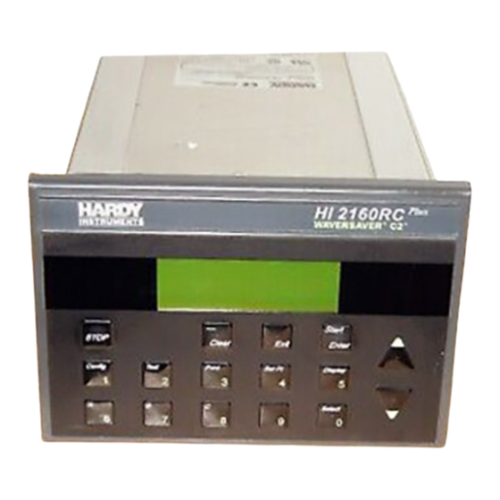
Hardy Process Solutions HI 2160RC PLUS Operation And Installation Manual (220 pages)
Rate Controller
Brand:
Hardy Process Solutions
| Category:
Controller
| Size: 4.32 MB
Table of Contents
Table of Contents
3
Fig. 1-1 Hi 2160Rc Plus Rate Controller
14
Fig. 1-2 Model Code Breakdown
16
Fig. 1-3 Optional Expander Box (Non-Fm)
17
Analog Output Option Card
20
Quad Option Expander Box - Basic Function
20
Chapter 3 Installation
24
Unpacking
24
Installing the HI 2160RC PLUS in a Panel
25
Mechanical Installation
25
Panel Cutout Specifications
25
Enclosure Size Requirements
25
Dimensions of the Enclosure Cutout (See Fig. 3-3)
25
Installing the HI 2160RC PLUS Panel Mount
25
Fig. 3-1 2" Clearance Requirement
25
Fig. 3-2 1" Clearance Require Around Bezel
26
Fig. 3-3 Panel Cutout Dimensions
26
Fig. 3-4 Mounting Controller in Panel
27
Fig. 3-5 Nema 4 Gasket Flush against the Front Panel
27
Fig. 3-6 Controller Flush to Front Panel/Front View
28
Fig. 3-7 Controller Flush to Front Panel/Rear View
28
Fig. 3-8 Installing Mounting Bars
29
Fig. 3-9 Installing 6-32 Machine Screws
29
Fig. 3-10 Nema 4 Gasket before and after Tightening the Mounting Bar Fasteners
30
Installation of HI 2160RC PLUS - RM Remote Panel Model
31
Fig. 3-11 Mounting Bars and Machine Screws Installed
31
Fig. 3-12 Front Panel with Brackets from Factory
32
Fig. 3-13 Bezel Installation Diagram
32
Fig. 3-14 Sliding Bezel into the Panel Cutout
33
Fig. 3-15 Remote Panel Installed
34
Fig. 3-16 Electronics Mounted to Enclosure Rear Panel
35
Fig. 3-17 Dimensions Diagram for Remote Mount
35
Installation of the HI 216EX Quad Expander Box
36
Fig. 3-18 Pin Cable Assembly Hi 2160Plus Remote Panel
36
Electrical Installation
37
Cabling and Interconnecting
37
Recommended Installation Procedures
37
Fig. 3-19 Quad Expander Installed
37
Output Relay Wiring Diagram
38
Speed Control Output Wiring Diagram
38
Fig. 3-20 Rear Panel
38
Fig. 3-21 Output Relay Connection
38
Refill and Alarm Relays Diagram
39
RS 232 Port Wiring Diagram
39
Fig. 3-22 Motor Control Output
39
Fig. 3-23 Refill and Alarm Relays
39
Fig. 3-24 Rs 232 Wiring Diagram
39
Remote Functions Wiring Diagram
40
Input Power Wiring Diagram
40
Fig. 3-25 Remote Functions Wiring Diagram
40
Remote Setpoint Option Wiring Diagram
41
Converter Option Wiring Diagram
41
Analog Output Option Wiring Diagram
41
Fig. 3-26 Power Connection Wiring Diagram
41
Fig. 3-27 Remote Setpoint Option Wiring Diagram
42
Fig. 3-28 Rs-422 Converter Option Wiring Diagram
42
Fig. 3-29 Analog Output Option Wiring Diagram
42
Load Cell Wiring Diagram
43
Installation
44
Fig. 3-30 C2 Load Cell Wiring Diagram
44
Fig. 3-31 4 Conductor Load Cell Wiring Diagram
44
Remote I/O Interface for the allen Bradley Network
45
PROFIBUS Interface Option
45
Fig. 3-32 6 Conductor Load Cell Wiring Diagram
45
Interconnect Wiring Diagram
46
Fig. 3-33 Interconnect Wiring Diagram
46
Computer Clean Power Requirement
47
Installing the Secure Memory Module
47
Fig. 3-34 Computer Clean Power Diagram
47
Fig. 3-35 Secure Memory Module
48
Fig. 3-36 Installing/Removing Secure Memory Module
48
Chapter 4 Configuration
50
About Chapter 4
50
Output Relay Configuration
50
Refill and Alarm Relays
50
Solid State Relays
50
Dip Switch Configuration
50
Fig. 4-1 Solid State Relay Dip Switches (Prt. #0535-0417)
50
Speed Control Output Card (Prt. #0535-0406)
51
Analog Output Card Option Configuration (Prt.# 0535-0406)
52
About the Analog Output Card Option
52
Fig. 4-2 Jumper Settings for Control Output Board
52
Setting the Jumpers
53
Plus
53
Fig. 4-3 Removal of Rear Panel
54
Fig. 4-4 Removal of Top Panel
54
Fig. 4-5 Removing Rear Panel in Quad Expander Box
54
Remote Function Inputs
55
Fig. 4-6 Analog Output Option Card
55
Remote Set Point Input Option Card Configuration (Prt. #0535-0410)
56
About Remote Set Point Input Option (Analog In)
56
Fig. 4-7 Remote Function Option
56
Setting the Jumpers
57
Setting the Jumpers in the HI 2160RC PLUS
57
Setting the Jumpers in the Optional Quad Expander Box
57
Connector Pins for Input Voltage and Current Input
58
Fig. 4-8 Jumper Settings for Analog Input Pwa and F1 Fuse
58
Grounding the Remote Pin to Read the Remote Set Point Input
59
Fig. 4-9 Connector Pins for Analog Input Pwa
59
Remote I/O Interface for the allen Bradley Network Option (-B2)
60
PROFIBUS Interface Option (-B4)
60
Setting the Dip Switches
60
Fig. 4-10 Ground Jumper to Read Analog Input
60
Rear Panel Config. Option Dip Switch Settings
61
Option Configuration Dip Switch
61
Fig. 4-11 Rs-422 Converter Dip Switches
61
Power up Process
62
Pre Power up Check Procedures
62
Proper Power up Indicators
62
Fig. 4-12 Config. Dip Switches Rear Panel
62
Waversaver
63
Effects of Vibration on a Scale
63
Configuring WAVERSAVER
63
Fig. 4-13 Operational Display #1 Current Weight
63
Fig. 4-14 Removal of Rear Panel
64
Fig. 4-15 Removal of Top Panel
64
Fig. 4-16 Setting Waversaver Jumpers
65
Some Things to Remember When Changing the Jumper Settings
66
Calibration
68
About Chapter 5
68
Pre-Calibration Procedures
68
Mechanical Check Procedures
68
Checking the Load Cell Installation
68
Check for Binding on the Load Cell
68
Check for Binding on Platform Scale/Feeder
69
Electrical Check Procedures
69
Load Check
69
Fig. 5-1 Properly Installed Load Cell W/No Binding
69
Weight Calibration Process
70
Calibration Setup Procedures
70
Setting the Mass Units
70
Setting the Time Units (Rate of Flow)
71
Setting the Rate Decimal Points
71
Setting the Batch Decimal Point
71
Setting the Total Decimal Point
72
Setting the Graduations
72
C2 Calibration Process
73
Hard Calibration Process (with Calibrated Test Weights)
74
ZERO Calibration Procedures
74
SPAN Calibration Procedures
74
Setting the Sticker Value
75
Rate Calibration Process
76
Feeder System Verification Procedures
76
Fig. 5-2 Operational Display/Not Running
77
Fig. 5-3 Operational Display Running
78
Fig. 5-4 Output Signal in 00.1% Increments
78
Fig. 5-5 Output Signal in 10% Increments
79
Fig. 5-6 Operational Display Unit Paused
80
Fig. 5-7 Operational Display off
80
Automatic Rate Calibration Procedures
81
Setting REC to Zero
81
Enter the PAUSE TIME Value
81
Enter the PRIME TIME Value
82
Enter the FEED TIME Value
82
AUTO RATE CALIBRATION from the Front Panel
82
AUTO RATE CALIBRATION Using a Serial Command
82
The Instrument Does the Following
82
Fig. 5-8 Auto Rate Calibration Passed
83
Fig. 5-9 Auto Rate Calibration Failed
84
Manual Rate Calibration Procedures
85
Fig. 5-10 Operational Display #1 Current Weight
86
Fig. 5-11 Scale Display
86
Gathering Rate Calibration Data Method #1
87
Materials Required
87
Gathering Rate Calibration Data Method #2
88
Materials Required
88
Slow Feed Rate
88
High Feed Rate
89
Entering the Calibration Values
89
Entering the High Rate Calibration Data
90
The Manual Rate Calibration Is Complete
90
Chapter 6 Setup
92
Display Menu Trees
92
Display Menu Flow Chart with Standard Serial Port
92
Display Menu Flow Chart with allen Bradley Remote I/O Option
93
Display Menu Flow Chart with PROFIBUS Interface Option
93
Front Panel Display
93
Function/Numeric Buttons
94
Config/1 Button
94
Security Sub-Menu
94
Security Access Levels
94
Fig. 6-1 Press Config/1 Button to Get to the Main Menu
95
Fig. 6-2 Security Code Entry Display
95
Setting the Security Access Levels
96
Fig. 6-3 Selecting Security Sub-Menu
96
Fig. 6-4 Security Menu, Selecting Access Levels
96
Setting the Security Code Numbers
97
What to Do if You Lose the HI Security Code Number
98
When to Use the Select Button
98
When to Use the Clear Button
98
Fig. 6-5 Security Menu, Entering Level Values
98
How to Exit a Sub-Menu Without Changing the Values
99
Tuning and Control Sub-Menu
99
Tuning/Control (Sec) Parameter Definitions
100
Fig. 6-6 Act Blank Timebase Error
100
Fig. 6-7 Derived Loss of Weight Slope
101
Fig. 6-9 Derived Loss of Weight Slope
102
Fig. 6-10 Entering Timebase Parameter
104
Fig. 6-11 Setting the Avrg and Rec Levels
105
Set the OP% to 99.9
106
Gathering Data
106
Fig. 6-12 Operating Display Total Weight
106
Calculate the K(Pu) Value (Initial K(P)
107
Calculate the Ultimate Oscillation Cycle Time (Tc)
107
Calculate the Time of Repeat (Tr)
107
Enter the New Control Constants
107
Manual Tuning Control Process (Cont'D)
108
Fig. 6-13 Entering Calculated Constant Values
108
Fig. 6-14 Operational Display/Rec Status
109
Rate Tolerance Sub-Menu
110
Setting the lo ALARM Tolerance
110
Setting the HI ALARM Tolerance
111
Setting the ALARM TIME (Sec.)
111
Setting the HI and lo Shutoff
112
Fig. 6-15 Grounding the "A" Pin to Clear Alarm
112
Setting the Shutoff out Percentage
113
Fig. 6-16 Rate Tolerances Menu/Shutoff Settings
113
Process Example Using Rate Tolerances
114
Fig. 6-17 Process Graph Using Rate Tolerances
114
Auto Refill Sub-Menu
115
About the Auto Refill Sub-Menu
115
Fig. 6-18 Auto Refill Output Relay
115
Selecting the Auto Refill Function
116
Fig. 6-19 Auto Refill Menu/Start and Stop Settings
116
Setting the START (LO) and STOP (HI) Parameters
117
Setting the lo SHUTOFF and HI SHUTOFF Alarm Weight Parameters
117
Fig. 6-20 Auto Refill Menu/Lo Shutoff Settings
118
Selecting the Initial Fill Function
119
About the Refill Correction Factor
119
Fig. 6-21 Auto Refill Menu/Hi Shutoff Settings
119
Force Refill
120
Fig. 6-22 Auto Refill Menu/Setting the Refill Correction
120
Time and Date Sub-Menu
121
Setting the Time
121
Fig. 6-23 Grounding Refill for Forced Refill
121
Fig. 6-24 Main Menu/Setting Time and Date
121
Setting the Date
122
Specifications See Chapter 2)
122
Fig. 6-25 Time and Date Menu/Setting Time and Date
122
Fig. 6-26 Main Menu/Selecting Serial Port #1
123
Fig. 6-27 Serial Port #1 Configuration
123
Fig. 6-28 Serial Port #1 Configuration
124
Fig. 6-29 Operational Menu
124
Printing Batch Reports
126
Fig. 6-30 Disabling the Print Function
126
Bi-Directional Port Setup
127
Fig. 6-31 Config Dip Switch #3/Disabling Batch Report Printing
127
Saving to the Secure Memory Module (SMM)
128
When to Save
128
Fig. 6-32 Saving to Secure Memory Module
129
Fig. 6-33 Save/Recall Menu
129
Data Saved in the Secure Memory Module
130
Restoring Data Saved in the Secure Memory Module
130
Data Recall Procedures
130
Setting the Control out LO% and Control out HI
131
Setting the Control out lo
131
Fig. 6-34 Recall Sub-Menu
131
Fig. 6-35 Control Out% Graph
132
Fig. 6-36 Tuning/Control Menu/Setting Control out lo
133
Setting Control out HI
134
Fig. 6-37 Tuning/Control Menu/ Setting Control out lo
134
Fig. 6-38 Tuning/Control Menu/Setting Control out Hi
135
Setting up the Analog Output Option
136
Fig. 6-39 Tuning/Control Menu/Setting Control out Hi Percentage/74
136
Analog Output Main
137
Fig. 6-40 Main Menu/Analog Output
137
Fig. 6-41 Analog Output Menu
137
The Information Type Parameter Setting
138
ZERO Output Reference Voltage and Current
138
SPAN Output Reference Voltage and Current
138
Fig. 6-42 Analog Output Menu/Zero and Span Voltage Setting
139
Serial Communications
140
About Chapter 7
140
System Configuration
140
Host Functions
140
Serial Protocol
140
Hardy Link
140
Multidrop Configuration
140
Serial Commands
141
Serial Command Lists
141
Fig. 7-1 Multidrop Configuration with Host and Controllers
141
Data Transmission Format
144
Command Sets
146
Xmit) Command
146
S (Set) Command
149
Error Codes
149
Operation
152
About Chapter 8
152
Operational Displays
152
Selecting Operational Displays
152
There Are Three Continuous Rate Displays
152
Fig. 8-1 Rate & Current Weight Display (Default Display)
152
Fig. 8-2 Rate & Total Weight Display
153
Fig. 8-3 Current Total Weight Display
153
The Rate Section
154
The Weight Section
154
Fig. 8-4 Rate Display
154
Current Weight Total Display
155
Fig. 8-5 Total Accumulated Weight
155
Batch Displays
156
Selecting Batch Displays
156
Fig. 8-6 Current and Accumulated Total Weight Display
156
Fig. 8-7 Set Point Menu/Selecting Batch Mode
156
Fig. 8-8 Batch Amount and Rate Display
157
Fig. 8-9 Batch Amount/Current Weight Display
158
Display Parameters
159
Rate\Current Weight Display Parameters
159
Fig. 8-10 Batch Amount and Total Weight Display
159
Fig. 8-11 Set Rate/Current Weight Display Parameters
159
Current\Total Weight Display Parameters
160
Clearing the Total Register (Totalizer) from the
160
Fig. 8-12 Current/Total Weight Display Parameters
160
Clearing the Total Register from the Rear Panel
161
Fig. 8-13 Clearing the Total Register from the Front Panel
161
Fig. 8-14 Clearing Total Register from the Rear Panel
161
Setting the Flow Rate
162
Rate Modes
162
Setting the Manual Rate Control Mode (Volumetric Mode)
162
Fig. 8-15 Operational Display Running
163
Increasing/Decreasing the OP% Output Signal by
164
Increments of .1
164
Fig. 8-16 Output Signal in 00.1% Increments
164
Set the Operating Percentage for 10% Increments
165
Setting the Remote Set Point Input Mode
165
Fig. 8-17 Output Signal in 10% Increments
165
Setting the Automatic Rate Control Mode (Gravimetric Mode)
166
Fig. 8-18 Selecting the Remote Mode of Operation
166
Amount Modes
167
Setting the Set Point Amount Batch Mode
167
Fig. 8-19 Setpoint Menu/Selecting Automatic Mode
167
Fig. 8-20 Setpoint Menu/Continuous Amount Mode
168
Fig. 8-21 Setpoint Menu/Set Point Amount Batching
168
Ratio Control (Master/Slave)
169
Description of a Ratio Controlled System
169
Ratio Process Control System
169
Remote Set Points Option for Ratio Control Applications
170
Fig. 8-22 Process Control System/Ratio Control
170
Fig. 8-23 Remote Set Point Jumper
171
Fig. 8-24 Setting lo and Hi Signal Output Parameters
172
Fig. 8-25 Remote Setpoint Menu/Setting Averaging
173
Fig. 8-26 Remote Setpoint Menu/Settin Spl & Sph
174
Ratio Control Application Example
176
Application
176
Setup
176
Fig. 8-27 Analog Signal Configuration Diagram
178
Rate Exception Control
179
Definition
179
Fig. 8-28 Downloading Set Points, Relay Wiring
179
Test Procedures
181
Sigma Test - Definition
181
Fig. 8-29 Selecting Test Menu
181
Fig. 8-30 Test Menu
182
Fig. 8-31 2 Sigma Test Menu
182
Fig. 8-32 2 Sigma Test Menu/Selecting the Test
183
Fig. 8-33 2 Sigma Test Menu/Selecting Yes
184
Fig. 8-34 Selecting Running 2 Sigma Display
185
Fig. 8-35 Selecting 2 Sigma Data
186
Fig. 8-36 2 Sigma Data Displayed
186
Troubleshooting and Repair
188
About Chapter 9
188
Disassembly and Reassembly Notes & Cautions
188
Start up
189
Auto Clear Ram Memory Procedures
189
System Troubleshooting
190
Drift
190
Checking if Drift Problem Is Internal or External
190
Fig. 9-1 Resistor Shunt Bridge Diagram
190
System Lock Ups
191
Fig. 9-2 Surge Suppression Resistive/Capacitive Circuit
193
Weights Displayed Are Incorrect
194
After Calibration Display Weight Reading Is Incorrect
194
Fig. 9-3 Test Sub-Menu/Checking Current Count
195
Feeder Motor Won't Start
196
Fig. 9-4 Using a Voltmeter to Check Load Cell Voltage
196
Fig. 9-5 Connector Wiring Diagram for Control Output Card
197
Fig. 9-6 Jumper Settings for Control Output Card
198
Erratic Actual Rate Readings
199
Rate Exception Control (REC) Alarm Appears too Often
199
Readings on the Display Are Not Correct
200
Remote Setpoint Input Card
201
Allen-Bradley RIO Error Codes for C2 Calibration
202
Allen-Bradley RIO Error Codes for Rate Calibration
202
PROFIBUS Error Codes for C2 Calibration
202
PROFIBUS Error Codes for Rate Calibration
203
HI 2160RC PLUS Error Messages
203
Operational Display Messages
205
Advertisement
Advertisement
Related Products
Hardy Process Solutions HIBS400 Series
Hardy Process Solutions HIFS-6060-10-PS-S
Hardy Process Solutions HIFS-4848-05-SS-S
Hardy Process Solutions HI 1769-2WS
Hardy Process Solutions HIFS-4848-10-SS-S
Hardy Process Solutions HIFS-3636-01-SS-S
Hardy Process Solutions HIFS-4848-02-SS-T
Hardy Process Solutions HIFS-4872-10-PS-S
Hardy Process Solutions HIFS-4860-05-PS-S
Hardy Process Solutions HIFS-3030-05-PS-S
Hardy Process Solutions Categories
Scales
Controller
Computer Hardware
Accessories
I/O Systems
More Hardy Process Solutions Manuals
Login
Sign In
OR
Sign in with Facebook
Sign in with Google
Upload manual
Upload from disk
Upload from URL