Advertisement
Quick Links
MECHANICAL INSTALLATION
Installing the HI 4060 Rate Controller in a Panel
3.100
4.05
3.200
3.000
2.590
1.274
.205
.41
.475
.755
.44
FIG. 1 PANEL HOLE DIMENSIONS
Step 1.
Make sure that all Electrostatic Discharge (ESD) precautions
are taken before and during installation.
Step 2.
Use the attached template to make the hole pattern in the panel
door or cover. (See Attached)
FIG. 2 PANEL MOUNT INSTALLATION
Step 3.
Use a phillips head screwdriver and install the five (5) 6-32 x
1/2 inch screws that fasten the bezel to the panel. (See Fig. 3)
Use a torque screw driver and torque each screw to 10 inch/
pounds. DO NOT OVERTIGHTEN!
Step 4.
Thread the four (4) threaded rods through the appropriate
holes in the panel and into the bezel. For the retrofit you don't
have to place the rods through the holes. (See Fig. 4)
Step 5.
Hand tighten each rod until you can no longer turn the rod. Do
not force the rods or use pliers of any kind.
Step 6.
Put the Display cable and connector through the 1 inch hole in
the panel door or cover and plug the display connector into the
display header in the bezel. (See Fig. 3)
Step 7.
Gently slide the electronic enclosure onto the threaded rods
while making sure the display cable glides easily into the
enclosure and does not kink. Move the electronic enclosure
toward the panel until it stops. (See Fig. 3)
QUICK INSTALLATION GUIDE
.172 THRU, 9 PL
1.25 THRU
INSTRUMENT
BEZEL OUTLINE
5.250
6.200
7.08
Step 8.
Thread the four (4) 6-32 thumb screws onto the threaded rods
until tight. Do not use pliers on the thumb screws.
DIN Rail Installation HI 4060 Rate Controller
Step 1.
Snap the DIN rail mounting feet into any of the two holes on
the front panel of the electronic enclosure. (See Figs. 5 & 6)
FIG. 3 DIN RAIL MOUNTING FOOT
FIG. 4 VERTICAL AND HORIZONTAL ORIENTATION
Step 2.
When installing firmly push the mounting feet until you hear a
snapping sound. The snap means they are mounted correctly.
Step 3.
After installation give each mounting foot a little tug to make
sure they are seated correctly.
NOTE:
There are several horizontal and vertical mounting
options. It is highly recommended that at least two
mounting feet be used per enclosure.
Step 4.
To mount the enclosure onto a DIN rail. Place the mounting
feet on the DIN Rail and firmly press down until the mounting
feet snap onto the rail.
Advertisement

Related Manuals for Hardy Process Solutions HI 4060


Summary of Contents for Hardy Process Solutions HI 4060
- Page 1 Thread the four (4) 6-32 thumb screws onto the threaded rods until tight. Do not use pliers on the thumb screws. Installing the HI 4060 Rate Controller in a Panel DIN Rail Installation HI 4060 Rate Controller .172 THRU, 9 PL 3.100...
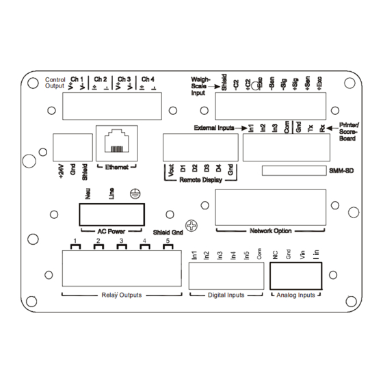
- Page 2 Earth Ground • SIG- White • SIG+ Green Step 1. The HI 4060 is configured with a universal power supply rated • SEN+ Blue from 110 to 240 VAC. • EXC+ Step 2. Make sure the VAC power is shut off before installing the wires to the connector.
- Page 3 Step 4. Apply VDC power to the unit. STARTING THE HI 4060 Step 1. Connect the power connector (AC or DC) to the HI 4060. Step 2. The Instrument boots up to the Summary Display. (See Fig. 9) Rate FIG. 7 SUMMARY DISPLAY Step 3.
Need help?
Do you have a question about the HI 4060 and is the answer not in the manual?
Questions and answers