
Related Manuals for Mellanox Technologies Vantage 8500


Summary of Contents for Mellanox Technologies Vantage 8500
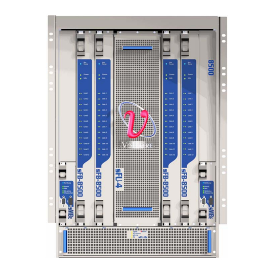
- Page 1 Mellanox Vantage 8500 288 Port Switch Installation Manual Rev A04 www.mellanox.com...
- Page 2 Mellanox®, BridgeX®, ConnectX®, InfiniBlast®, InfiniBridge®, InfiniHost®, InfiniRISC®, InfiniScale®, InfiniPCI®, PhyX® and Virtual Protocol Interconnect® are registered trademarks of Mellanox Technologies, Ltd. CORE- Direct and FabricIT are trademarks of Mellanox Technologies, Ltd. All other marks and names mentioned herein may be trademarks of their respective companies.
-
Page 3: Table Of Contents
About this Manual Contact Us Intended Audience Document Conventions Textual Conventions Related Documentation Chapter 1 Product Overview 1.1 The Vantage 8500 Switch 1.2 Physical Description 1.2.1 Chassis 1.2.2 Plug-in Modules - Overview 1.3 Block Diagram 1.4 Product Options 1.4.1 Basic Hardware Configuration 1.4.2 Full Hardware Configuration... - Page 4 7.4.2 Fabric Board (sFB-8500) LED Indicators 7.5 Power Supply Unit (sPSU-S) LED Indicators 7.5.1 Fan Unit LED Indicators 7.5.2 Management Board (sMBE) LED Indicators 7.5.3 Control Board (sCTRL) LED Indicators Appendix A Port Pinouts RJ-45 Management Port DB-9 Serial Port Mellanox Technologies...
- Page 5 Figure 27: Chassis Grounding Holes Figure 28: Top Grounding Connection (Grounding Stud Installed) Figure 29: Grounding Stud Installation Figure 30: Mounting a Basic Vantage 8500 Switch Chassis in a Rack Figure 31: Chassis Secured onto the Front Rack Rail Figure 32: Cabling Guide Brackets Figure 33: Screws, 3/8"...
- Page 6 Figure 48: Line Board (sLB-1024) Front Panel Figure 49: Fabric Board (sFB-8500) Front Panel Figure 50: Power Supply Unit (sPSU-S) Front Panel Figure 51: Horizontal Fan Unit (sFU-8E) Front Panel Figure 52: Management Board (sMBE) Front Panel Figure 53: Control Board (sCTRL) Front Panel Mellanox Technologies...
- Page 7 Rev A04 List of Tables Table 1: Conventions Table 2: Vantage 8500 Switch - Part Naming Conventions Table 3: Vantage 8500 Switch Line Board Components Table 4: Vantage 8500 Basic Hardware Configuration Table 5: Vantage 8500 Full Hardware Configuration Table 6:...
-
Page 8: About This Manual
Rev A04 About this Manual This manual describes how to install the Vantage 8500. We sometimes update the printed and electronic documentation after original publica- tion. Therefore, review the documentation on http://www.Mellanox.com for any updates. Please refer to the official and latest product release notes for last-minute updates. -
Page 9: Contact Us
Rev A04 Contact Us Please send your documentation-related comments and feedback or report mistakes to docs@Mel- lanox.com. We are committed to improving our documentation and your feedback is important to us. Mellanox Technologies... -
Page 10: Intended Audience
Intended Audience This manual is for system administrators responsible for installing the Mellanox Vantage 8500 10GbE Layer-2 core switch, hereafter referred to as Vantage 8500. We assume you are familiar with the concepts and terminology of Ethernet and local area networking. -
Page 11: Document Conventions
Warns you that failure to take or avoid a specific action might result in personal injury or a malfunction of the hardware or software. Be aware of the hazards involved with electrical circuitry and be familiar with standard practices for pre- venting accidents before you work on any equipment. Mellanox Technologies... -
Page 12: Textual Conventions
(for example, buttons and icons). User text entered into Env1”, “Network1 Note the quotes. The text entered does not include the Manager, e.g., to assign quotes. as the name of a logical object Mellanox Technologies... -
Page 13: Related Documentation
Rev A04 Related Documentation For additional information, see the following documents: • Mellanox Vantage 8500 10GbE Layer-2 Core Switch User Manual • Release Notes for the Mellanox Vantage 8500 Switch • Regulatory Compliance and Safety Reference Guide Mellanox Technologies... -
Page 14: Chapter 1 Product Overview
Layer-2 core switch, optimized for enterprise data center and cloud computing environments. The Vantage 8500 switch is one of the most power-efficient and lowest latency Ethernet switches avail- able, enabling new levels of efficiency, scalability, and real-time application performance, while at the same time consolidating multiple or redundant network tiers and helping reduce infrastructure expenses. -
Page 15: Physical Description
This section provides a description of the Vantage 8500 components. 1.2.1 Chassis The Vantage 8500 chassis is 15U high plus; mounting hardware requires 1/3 of 1 U either above or below the chassis, 17.5 inches wide (19 inches with the fixed side brackets), and 22.75 inches deep. -
Page 16: Plug-In Modules - Overview
1.2.2 Plug-in Modules - Overview As a modular system, the Vantage 8500 switch comprises plug-in modules that are installed into its chassis. The following table summarizes the part types and their respective Mellanox names. Table 2 - Vantage 8500 Switch - Part Naming Conventions... -
Page 17: Figure 4: Line Board (Slb-1024)
A single sLB-1024 line board module provides 24 10GbE ports for the Vantage 8500 switch, as shown. You can install up to 12 line boards in the Vantage 8500 switch (via the back panel), depending on the required hardware configuration. -
Page 18: Figure 5: Fabric Board (Sfb-8500)
The sFB-8500 fabric board is a main CPU and traffic processing unit for the Vantage 8500 switch. You can install up to 4 fabric boards (1, 2, 3 or 4) in the Vantage 8500 switch (via the front panel), depending on the required hardware configuration. -
Page 19: Figure 6: Management Board (Smbe)
Figure 6: Management Board (sMBE) 1.2.2.5 Power Supply Unit (sPSU-S) A sPSU-S module is a hot-swappable power supply unit for the Vantage 8500 switch. You can install up to 5 power supplies in the chassis, depending on the number of installed modules (line boards, fabric boards...) and the power they require, without power supply redundancy. -
Page 20: Figure 8: Vertical Fan Unit (Sfu-4)
The control board (sCTRL), as shown, allows connection to a local out-of-band terminal control station, via an Ethernet (up to 100 Mbps) or a serial interface (RS-232) connection. The board includes two Ethernet interfaces (RJ-45) and two serial interfaces (DB-9). Mellanox Technologies... -
Page 21: Block Diagram
For more information, See “Control Board (sCTRL) LED Indicators” on page 79.. Block Diagram The following figure illustrates the basic physical and logical structure of the Vantage 8500 switch, which comprises the mid-plane, the backplane, and plug-in modules: Figure 11: Vantage 8500 Block Diagram... -
Page 22: Basic Hardware Configuration
Full Hardware Configuration See “Full Hardware Configuration” on page 22. 1.4.1 Basic Hardware Configuration The basic hardware configuration of the Vantage 8500 switch includes the minimum number of hardware components, as specified in the following table. Table 4 - Vantage 8500 Basic Hardware Configuration... -
Page 23: Figure 12: Vantage 8500 Switch -Front View
Rev A04 Table 5 - Vantage 8500 Full Hardware Configuration Hardware Component Maximum Quantity Management boards (sMBE) Control board (sCTRL) Figure 12: Vantage 8500 Switch -Front View Mellanox Technologies... -
Page 24: Technical Specifications
Product Overview Figure 13: Vantage 8500 Rear View in Full Hardware Configuration Technical Specifications This section describes the technical specifications of the components of the Vantage 8500 switch. 1.5.1 Chassis • 15U height, 19” rack mountable; mounting hardware requires 1/3 of 1 U •... -
Page 25: Fabric Boards (Sfb-8500)
LED Indicators – For LED assignments see See “Control Board (sCTRL) LED Indicators” on page 79. 1.5.6 Fan Modules • Vertical (sFU-4) & Horizontal (sFU-8E) Fan Units • Hot pluggable; Normal and Turbo fan speeds • sFU-8E LED Indicators • Temp Mellanox Technologies... -
Page 26: Power Supply Unit (Spsu-S)
Maximum theoretical power consumption for a fully-configured chassis: 4,300 Watts max • Typical power consumption for a fully-configured chassis: 4,170 Watts max • For typical configuration - 10 watt per port • Optic port adds 1 watt per port Mellanox Technologies... -
Page 27: Power Supply Calculation Example
W per port AC line Power per port 1.5.9 IEEE Compliance The following protocols are supported: • 802.1 • 802.1Q VLAN • 802.1d STP • 802.3 • 802.3ae • 802.3ad Link aggregation/LACP (16 ports/channel) • 802.3x Flow Control. Mellanox Technologies... -
Page 28: Datacenter Bridging (Cee)
Ambient temperature: 0° to 45°C (32° to 113°F) • Humidity: 15% to 80% non-condensing • Altitude: 0 to 3000m (9,843 ft.) • Storage: • Temperature: -25° to 70°C (-13° to 158°F) • Humidity: 5% to 90% non-condensing • Altitude: 0 to 4570m (15,000 ft.) Mellanox Technologies... -
Page 29: Acoustic Data
Japan VCCI Technical Requirements, V.3/2001.04/CISPR 22:1997 + A1: 2000 + A2: 2002, Class A. • Australian/New Zealand C-Tick, AS/NZS CISPR 22:04 • KCC Korea • Restricted Hazardous Substances: • RoHS-6 For more information, see the Regulatory Compliance and Safety Information Reference Guide. Mellanox Technologies... -
Page 30: Reliability (Mtbf) Data
Mellanox products comply with the Radio & Telecommunications Terminal Equipment Directive 99/5/EEC, the EMC Directive 2004/108/EC, and of the Low Voltage Directive 2006/95/EC. 1.7.2 Hazardous Substances (RoHS 6) Compliance The Vantage 8500 switch complies with the RoHS directive (RoHS 6). Mellanox Technologies... -
Page 31: Statement Of Volatility
Please refer to the Statement of Volatility for the Mellanox Vantage 8500 Switch. Shock and Vibration Test Report When shipping the Vantage 8500 switch in a rack, carefully follow the rail kit installation instruc- tions, See “Assembling and Mounting the Rails” on page 45.. -
Page 32: Table 9: Drop Tests
Table 9 - Drop Tests Parameter Value Drop height 0.1 meter Number of drops per item One drop performed on the bottom face, 2 edges and 2 corners of the test item Total number of drops 5 drops Mellanox Technologies... -
Page 33: Chapter 2 Installation Requirements
Rack and Clearance Requirements The 15U high chassis of the Vantage 8500 switch is mounted in a standard 19" rack with the sFB- 8500 and sMBE boards facing to front of the rack, and the sLB-1024 boards with their 10GbE ports facing to the rear. -
Page 34: Power Requirements
Power requirements are useful for planning the power distribution system needed to support the Vantage 8500 switch. Heat dissipation is an important consideration for sizing the air conditioning requirements for an installation. Verify the available power source at the site for the type of device you are installing. -
Page 35: Power Redundancy (N:1 And N:n)
AC power into usable DC power 2.4.2 Power Redundancy (N:1 and N:N) The Vantage 8500 switch features hot-swappable power supply units that can work in N:1 or N:N redundancy mode. A non-redundant power configuration includes the minimum number of power supplies required by the system for operation. -
Page 36: Required 10Gbe Cables And Port Adapters
Rev A04 Installation Requirements The Vantage 8500 switch supports up to two load-sharing 1400W supply modules. The amount of required power supplies per system is set according to system configuration. When the Vantage 8500 switch is fully configured, it supports N:1 redundancy, as shown. -
Page 37: Required Control And Management Cables
If you use a local terminal, use standard serial cables (RS-232) to connect to the serial manage- ment ports located on either the sCTRL module or the sMBE modules. For the DB-9 port pin assignments, See “Port Pinouts” on page 81.. Mellanox Technologies... -
Page 38: Required Installation Tool
Rev A04 Installation Requirements Required Installation Tool The following materials and tools are required to mount the Vantage 8500 chassis into a rack: Table 15 - Tools Required for Hardware Installation Required Tool(s) Quantity Flat-blade screwdriver Phillips screwdriver Utility knife... -
Page 39: Chapter 3 Unpacking
Unpacking Packed Unit Dimensions and Weight The following table summarizes the weight and dimensions of the Vantage 8500 modules. Mod- ules that are not pre-installed in the chassis may be packed individually. Table 16 - Factory-Packed Unit Weight and Dimensions... -
Page 40: Unpacking The Switch
Rev A04 Unpacking Unpacking the Switch The following figure summarizes the box unpacking procedure: Figure 15: Unpacking Procedure for the Vantage 8500 Switch Mellanox Technologies... -
Page 41: Figure 16: Unpacking The Chassis
Top foam • Accessories To unpack the Vantage 8500 switch from its box: 1. Carefully cut the packing straps and open the carton box. 2. Remove the box from around the chassis by sliding it upwards, as shown. Mellanox Technologies... -
Page 42: Figure 17: Chassis Partially Unpacked
Getting Started Short Guide - Mellanox Solution • CD with documentation and software utilities fastened on top of the Vantage 8500 switch chassis wrapped in an antistatic bag. 3. Remove all the accessories listed above and the packing foam on top of the chassis. -
Page 43: Center Of Gravity Data
Rev A04 Center of Gravity Data CAUTION: To avoid injury, consider the Vantage 8500 switch weight and center of gravity data. The following illustrates the origin point (X=0, Y=0, Z=0) that is located at the lower left corner of the front of the chassis. -
Page 44: Packing For Re-Deployment
To pack the Vantage 8500 switch: 1. Insert the foam grip on the designed box pallet. 2. Position the Vantage 8500 switch chassis on the foam. Make sure the power supplies (rear of the chassis) are on the foam side marked sPSU-S side, as shown. -
Page 45: Chapter 4 Chassis Installation
Chassis Installation Mounting Process Summary The Vantage 8500 switch chassis is designed to be mounted in a standard 19" rack with the sFB- 8500 modules facing the front of the rack. An adjustable rail kit is supplied to accommodate racks of differing depths. -
Page 46: Figure 20: Rail Kit Components - Left Bracket, Right Bracket, Screws, Washers And Nuts
The rail supports six or eight 8-32 5/8" screws; eight are recommended. When assembling and mounting the rail, the required torque force is 10 lb. in (using a drill-like electric screwdriver). 3. Choose the threaded holes in the bracket. Mellanox Technologies... -
Page 47: Figure 21: Assembling The Rail Bracket And Insert
2. For each of left and right, take a bracket and attach an insert panel (the two inserts are identi- cal). At this stage, position the two parts to fit the distance between the rack rails of each side. Mellanox Technologies... -
Page 48: Figure 22: Positioning The Insert In Front Of The Right Bracket
Figure 22: Positioning the Insert In Front of the Right Bracket Figure 23: Assembling an Insert to a Rail Bracket (Inside View) 3. Choose the threaded holes in the bracket. 4. Assemble the rail with flat washers, spring washers, and nuts, but do not tighten the screws yet. Mellanox Technologies... -
Page 49: Figure 24: U Alignment
Rack (requires 1U clearance below). Figure 24: U Alignment • Above the U mark: position the Rail Brackets and align them with the hole above the “U” mark on the Rack (no need for 1U clearance below). Mellanox Technologies... -
Page 50: Figure 25: Above U Alignment
The following figures show the left rail completely assembled and how it looks when it is attached to the rack. Figure 26: Mounting the Rail - Left Side Front and Rear View 7. Tighten the screws that were used to connect the two parts of the rail in Step 1. Mellanox Technologies... - Page 51 3 spring washers • 2 nuts #10 • Ground label • Safety warning label. The Vantage 8500 switch has two grounding connections (grounding holes) as shown. For conve- nience, grounding can be performed from either of these locations. Mellanox Technologies...
-
Page 52: Figure 27: Chassis Grounding Holes
Figure 28: Top Grounding Connection (Grounding Stud Installed) The grounding procedure requires a 10 AWG Grounding Cable. To install the grounding stud and grounding cable: 1. Insert a 10-32 5/8" screw through a grounding hole, rear-to-front, as shown. Mellanox Technologies... -
Page 53: Mounting The Chassis In The Rack
9. Attach the Safety Warning label on the side of the chassis, near the grounding stud. 4.1.2 Mounting the Chassis in the Rack This section explains how to mount the Vantage 8500 switch in a 19" rack. Screws and clip nuts to connect the chassis to the rack and rail kit to rack are not supplied. - Page 54 Make sure that the grounding stud is installed prior to the chassis installation. To install the Vantage 8500 chassis in the rack: 1. Lift the chassis and place it on the rails, with the front of the chassis towards you as shown, and then slide the chassis into place.
-
Page 55: Figure 30: Mounting A Basic Vantage 8500 Switch Chassis In A Rack
Rev A04 Figure 30: Mounting a Basic Vantage 8500 Switch Chassis in a Rack 2. Secure the chassis onto the rack by aligning the holes at the front of the chassis with the mounting holes on the rack's vertical front rail. -
Page 56: Installing Cabling Guide Brackets
The cabling guide brackets provide a convenient way to arrange the many cables that are con- nected to the switch. They are installed on the rear side of the rack rails, on the right and left hand sides. Figure 32: Cabling Guide Brackets Mellanox Technologies... -
Page 57: Shipping Guidelines And Instructions
(with the switches in them) to the customer sites. Such shipping requires extreme caution and preparation in advance. If the rack is shipped with the Vantage 8500 switch installed in it, it is absolutely critical to further stabilize the chassis for transport, as explained in the following procedure. -
Page 58: Figure 34: Screws On Chassis Side Wall
Figure 34: Screws on Chassis Side Wall Once the rack is delivered and installed on the customer site, these screws should be removed so that you can remove the chassis in case the sides of the rack are not accessible. Mellanox Technologies... -
Page 59: Chapter 5 Installing Modules
Rev A04 Installing Modules The Vantage 8500 switch line boards and modules are delivered pre-installed in the chassis, and depending on your original order. This chapter is intended to guide you when you install additional modules, or when a certain module has to be removed and then re-installed. -
Page 60: Figure 36: Fabric Board Slot Numbering
Rev A04 Installing Modules Table 18 - Fabric Board Insertion Fabric Board Slot # Figure 36: Fabric Board Slot Numbering Slot #1 Slot #2 Slot #3 Slot #4 Mellanox Technologies... -
Page 61: Extracting/Inserting Boards
On each module, the blue hot-swap LED indicates when the board is ready to be removed from the chassis. The ejectors snap inward to lock the board into place and may include a red button to disengage the lock and electrically notify the system that an extraction has been requested. Mellanox Technologies... -
Page 62: Figure 37: Using Ejectors To Extract A Board
Four screws on each board complete the seating and lock of the board in place. When using a drill-like electric screwdriver to fasten the board screws in place, do not use more than Torque 3 force (10 lb. in) as this could damage the screws. Mellanox Technologies... -
Page 63: Installing A Fabric Board (Sfb-8500)
To extract an installed sFB-8500 from the chassis: 1. Release/unlock the security screws. 2. Press the red tabs to unlock the ejectors. 3. Wait for the blue Hot-Swap LED to light. 4. Press the ejectors outwards and slowly slide out the board. Mellanox Technologies... -
Page 64: Installing A Line Board (Slb-1024)
5.3.3 Installing a Line Board (sLB-1024) You can install up to 12 line boards at the rear side of the Vantage 8500 chassis. When installing the sLB-1024 boards, start at the bottom of the chassis and work your way up to avoid friction between components of adjacent line boards. -
Page 65: Installing A Management Board (Smbe)
3. Press the ejector clips inwards until the locks snap. 4. Tighten the four security screws. It is recommended to tighten the screws in a "crisscross" sequence (top right, bottom left, top left, bottom right). 5. Check the LED indicators. Mellanox Technologies... -
Page 66: Extracting A Management Board (Smbe)
1. Disconnect CLI and I2C cables from the specific board. 2. Release the security screws. 3. Press the red tabs to unlock the ejectors. 4. Wait for the Blue Hot Swap LED to light. 5. Press the ejectors outwards and slowly slide out the board. Mellanox Technologies... -
Page 67: Installing A Power Supply Unit (Spsu-S)
• All power supplies must be powered simultaneously. If not powered simultaneously, the system might not start properly. Extracting a Power Supply Unit (sPSU-S) To extract a sPSU-S from the chassis: 1. Disconnect the power cable. Mellanox Technologies... -
Page 68: Replacing A Control Board (Sctrl)
(Ethernet and Serial). It also includes a Reset button for the chassis. The Vantage 8500 chassis is pre-assembled at the factory with the sCTRL board installed. When using a drill-like electric screwdriver to fasten the board screws in place, do not use more than Torque 2 force (6 lb. -
Page 69: Replacing Fan Units (Sfus)
Figure 44: Securing the sCTRL Board Replacing Fan Units (sFUs) The Vantage 8500 chassis includes the sFU-4 and sFU-8E fan units, which are pre assembled at the factory. Both sFUs are hot swappable. At system startup, the fan speed is set to turbo mode until adequate temperature is reached. Fan speed is then set to normal mode. -
Page 70: Replacing The Sfu-4 Unit
(Optional) LED on the sFU-8E module. Replacing the sFU-8E Unit To replace the sFU-8E fan unit: 1. Loosen the screws that secure the sFU-8 to the chassis. 2. Hold the handles and remove the sFU-8 by sliding it out of the chassis. Mellanox Technologies... -
Page 71: Figure 46: Removing The Sfu-8E Unit
Rev A04 Figure 46: Removing the sFU-8E Unit 3. Replace with a new sFU-8 unit, slide it in carefully and tighten the screws. Figure 47: Securing the sFU-8E Unit 4. Listen for proper sFU-8 fan operation. Mellanox Technologies... -
Page 72: Chapter 6 Connector And Cable Specifications
• Do not over-tighten tie-wraps if used to secure cables. • Velcro straps are recommended • For the Vantage 8500 • Divide cables for each fabric board into two groups and route half from each side of the chassis. •... -
Page 73: Connecting The Unit To A Local Management Terminal
4" (10 cm). Connecting the Unit to a Local Management Terminal The Vantage 8500 switch has management ports located on the front panel. This includes two interfaces: a serial interface for local console access and a 10/100 Ethernet interface for network access: •... - Page 74 The last digit represents the physical position of the serial connector on the host. For exam- ple, if the host has only one serial connector, the device name should be /dev/ttyS0. If the host has two serial connectors, the device name could either be /dev/ttyS0 or /dev/ttyS1, and so on. Mellanox Technologies...
-
Page 75: Chapter 7 Final Checks, Operation And Troubleshooting
Final Checks, Operation and Troubleshooting Required Checks Before Initial Operation Once the Vantage 8500 chassis is secure within the rack and prior to powering-up the switch, per- form the following checks: 1. Ensure that all site power and grounding requirements have been met before connecting the chassis to a power source. -
Page 76: Line Board (Slb-1024) Led Indicators
Rev A04 Final Checks, Operation and Troubleshooting 7.4.1 Line Board (sLB-1024) LED Indicators The following types of LED indicators are located on a Vantage 8500 line board (up to 12 boards per chassis): Figure 48: Line Board (sLB-1024) Front Panel... -
Page 77: Power Supply Unit (Spsu-S) Led Indicators
General purpose LED for management usage Power Supply Unit (sPSU-S) LED Indicators The following types of LED indicators are located on a Vantage 8500 power supply unit (up to 5 units per chassis): Figure 50: Power Supply Unit (sPSU-S) Front Panel... -
Page 78: Fan Unit Led Indicators
ON – indicates that at least one of the main AC power supplies is faulty. 7.5.2 Management Board (sMBE) LED Indicators The following types of LED indicators are located on a Vantage 8500 management board (up to two boards per chassis):... -
Page 79: Control Board (Sctrl) Led Indicators
CM Active Indicates that the Chassis Management is running on the specific sMBE. (Green) 7.5.3 Control Board (sCTRL) LED Indicators The following types of LED indicators are located on the Vantage 8500 control board (one board per chassis): Mellanox Technologies... -
Page 80: Figure 53: Control Board (Sctrl) Front Panel
Eth 1 and 2 Each Ethernet port, used for the management interface, has two LEDs: • Link (Green) • Activity (Orange) • Reset Button • Press 1-6 seconds for soft reset • Press for more than 6 seconds for hard reset Mellanox Technologies... -
Page 81: Appendix A Port Pinouts
Rev A04 Appendix A: Port Pinouts Mellanox Technologies... -
Page 82: Management Port
The following table specifies the RJ-45 Ethernet management port pinout. Table 25 - RJ-45 Management Port Pinout Signal Description TxD+ Transmit data + TxD- Transmit data - RxD+ Receive data + No connection No connection RxD- Receive data - No connection No connection Mellanox Technologies... -
Page 83: Serial Port
The following table specifies the DB-9 terminal (RS-232) control port pinout. Table 26 - DB-9 RS-232 CLI Connector Pinout Signal Description No connection Receive data Transmit data No connection Ground No connection No connection No connection No connection Mellanox Technologies...
Need help?
Do you have a question about the Vantage 8500 and is the answer not in the manual?
Questions and answers