Sign In
Upload
Manuals
Brands
Mellanox Technologies Manuals
Switch
Vantage 8500
Mellanox Technologies Vantage 8500 Manuals
Manuals and User Guides for Mellanox Technologies Vantage 8500. We have
1
Mellanox Technologies Vantage 8500 manual available for free PDF download: Installation Manual
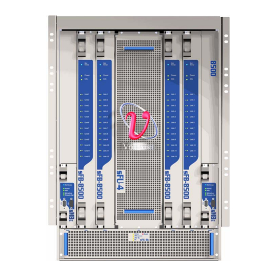
Mellanox Technologies Vantage 8500 Installation Manual (83 pages)
288 Port Switch
Brand:
Mellanox Technologies
| Category:
Switch
| Size: 2.43 MB
Table of Contents
Table of Contents
3
About this Manual
8
Contact Us
9
Intended Audience
10
Document Conventions
11
Table 1: Conventions
12
Textual Conventions
12
Related Documentation
13
Chapter 1 Product Overview
14
The Vantage 8500 Switch
14
Figure 1: Vantage 8500 Switches in a Scale-Out Ethernet Configuration
14
Physical Description
15
Chassis
15
Figure 2: Vantage 8500 Switch -Front View
15
Plug-In Modules - Overview
16
Figure 3: Vantage 8500 Switch - 3D Rear View
16
Table 2: Vantage 8500 Switch - Part Naming Conventions
16
Figure 4: Line Board (Slb-1024)
17
Table 3: Vantage 8500 Switch Line Board Components
17
Figure 5: Fabric Board (Sfb-8500)
18
Figure 6: Management Board (Smbe)
19
Figure 7: Power Supply Unit (Spsu-S)
19
Figure 8: Vertical Fan Unit (Sfu-4)
20
Figure 9: Horizontal Fan Unit (Sfu-8E) Front Panel
20
Block Diagram
21
Product Options
21
Figure 10: Control Board (Sctrl) Front Panel
21
Figure 11: Vantage 8500 Block Diagram
21
Basic Hardware Configuration
22
Full Hardware Configuration
22
Table 4: Vantage 8500 Basic Hardware Configuration
22
Table 5: Vantage 8500 Full Hardware Configuration
22
Figure 12: Vantage 8500 Switch -Front View
23
Technical Specifications
24
Chassis
24
Line Boards (Slb-1024)
24
Figure 13: Vantage 8500 Rear View in Full Hardware Configuration
24
Fabric Boards (Sfb-8500)
25
Management Board (Smbe)
25
Control Panel Sctrl
25
Fan Modules
25
Power Supply Unit (Spsu-S)
26
Power Supply Calculation Example
27
IEEE Compliance
27
Table 6: Power Calculation Table
27
Datacenter Bridging (CEE)
28
Layer-2 Capabilities
28
Physical/Electrical
28
Cooling
28
Physical Characteristics
28
Environmental
28
Acoustic Data
29
Certifications
29
Reliability (MTBF) Data
30
Declarations
30
Declaration of Conformity
30
Hazardous Substances (Rohs 6) Compliance
30
Table 7: MTBF Information Per Module
30
Statement of Volatility
31
Shock and Vibration Test Report
31
Table 8: Axes (X,Y,Z) Vibration Test for Transportation Without a Rack
31
Table 9: Drop Tests
32
Chapter 2 Installation Requirements
33
Site Planning
33
Heat Dissipation
33
Rack and Clearance Requirements
33
Power Requirements
34
Spsu-S Units - Power Usage/Requirements
34
Table 10: Rack Clearance Requirements
34
Power Redundancy (N:1 and N:N)
35
Table 11: Spsu-S - Detailed Power Usage Data
35
Required 10Gbe Cables and Port Adapters
36
Figure 14: Fully Configured Switch at N:1 Power Redundancy
36
Table 12: SFP+ Copper 10Gbe Cables
36
Required Control and Management Cables
37
Table 13: SFP+ Fiber Optic 10Gbe Transceivers (Required for Fiber Optic Cables)
37
Table 14: Fiber Optic Cables (Require SFP+ Transceivers)
37
Required Installation Tool
38
Table 15: Tools Required for Hardware Installation
38
Chapter 3 Unpacking
39
Packed Unit Dimensions and Weight
39
Package Contents
39
Table 16: Factory-Packed Unit Weight and Dimensions
39
Unpacking the Switch
40
Figure 15: Unpacking Procedure for the Vantage 8500 Switch
40
Figure 16: Unpacking the Chassis
41
Figure 17: Chassis Partially Unpacked
42
Center of Gravity Data
43
Figure 18: Center of Gravity Data
43
Table 17: Center of Gravity Data
43
Packing for Re-Deployment
44
Figure 19: Spsu-S Side Label on the Foam Spsu-S
44
Chapter 4 Chassis Installation
45
Mounting Process Summary
45
Assembling and Mounting the Rails
45
Figure 20: Rail Kit Components - Left Bracket, Right Bracket, Screws, Washers and Nuts
46
Figure 21: Assembling the Rail Bracket and Insert
47
Figure 22: Positioning the Insert in Front of the Right Bracket
48
Figure 23: Assembling an Insert to a Rail Bracket (Inside View)
48
Figure 24: U Alignment
49
Figure 25: above U Alignment
50
Figure 26: Mounting the Rail - Left Side Front and Rear View
50
Figure 27: Chassis Grounding Holes
52
Figure 28: Top Grounding Connection (Grounding Stud Installed)
52
Mounting the Chassis in the Rack
53
Figure 29: Grounding Stud Installation
53
Figure 30: Mounting a Basic Vantage 8500 Switch Chassis in a Rack
55
Installing Cabling Guide Brackets
56
Figure 31: Chassis Secured Onto the Front Rack Rail
56
Figure 32: Cabling Guide Brackets
56
Shipping Guidelines and Instructions
57
Figure 33: Screws, 3/8" Tooth Washer, and Flat Washers
57
Figure 34: Screws on Chassis Side Wall
58
Chapter 5 Installing Modules
59
Chassis Slot Numbering
59
Module Insertion Rules
59
Figure 35: Chassis Slot Numbering for Slb-1024 Modules
59
Table 18: Fabric Board Insertion
59
Figure 36: Fabric Board Slot Numbering
60
Extracting/Inserting Boards
61
Figure 37: Using Ejectors to Extract a Board
62
Installing a Fabric Board (Sfb-8500)
63
Extracting a Fabric Board (Sfb-8500)
63
Installing a Line Board (Slb-1024)
64
Extracting a Line Board (Slb-1024)
64
Figure 38: Extracting an Sfb-8500 Board
64
Installing a Management Board (Smbe)
65
Figure 39: Extracting an Slb-1024 Board
65
Extracting a Management Board (Smbe)
66
Figure 40: Securing the Smbe Board
66
Installing a Power Supply Unit (Spsu-S)
67
Extracting a Power Supply Unit (Spsu-S)
67
Figure 41: Extracting an Smbe Board
67
Replacing a Control Board (Sctrl)
68
Figure 42: Extracting a Spsu-S Unit
68
Replacing Fan Units (Sfus)
69
Figure 43: Removing the Sctrl Board
69
Figure 44: Securing the Sctrl Board
69
Replacing the Sfu-4 Unit
70
Replacing the Sfu-8E Unit
70
Figure 45: Securing the Sfu-4 Board
70
Figure 46: Removing the Sfu-8E Unit
71
Figure 47: Securing the Sfu-8E Unit
71
Chapter 6 Connector and Cable Specifications
72
Cabling-Do's and Don'ts
72
General Guidelines
72
Connecting 10Gbe Cables
72
Connecting the Unit to a Local Management Terminal
73
Chapter 7 Final Checks, Operation and Troubleshooting
75
Required Checks before Initial Operation
75
Powering-Up the Switch
75
Verifying Proper Switch Operation
75
Checking the LED Indicators
75
Line Board (Slb-1024) LED Indicators
76
Fabric Board (Sfb-8500) LED Indicators
76
Figure 48: Line Board (Slb-1024) Front Panel
76
Figure 49: Fabric Board (Sfb-8500) Front Panel
76
Table 19: Line Board (Slb-1024) LED Indicators
76
Power Supply Unit (Spsu-S) LED Indicators
77
Figure 50: Power Supply Unit (Spsu-S) Front Panel
77
Table 20: Fabric Board (Sfb-8500) LED Indicators
77
Fan Unit LED Indicators
78
Management Board (Smbe) LED Indicators
78
Figure 51: Horizontal Fan Unit (Sfu-8E) Front Panel
78
Table 21: Power Supply Unit (Spsu-S) LED Indicators
78
Table 22: Fan Unit LED Indicators
78
Control Board (Sctrl) LED Indicators
79
Figure 52: Management Board (Smbe) Front Panel
79
Table 23: Management Board Indicators
79
Figure 53: Control Board (Sctrl) Front Panel
80
Table 24: Control Board LED Indicators
80
Appendix A Port Pinouts
81
Management Port
82
Serial Port
83
Advertisement
Advertisement
Related Products
Mellanox Technologies 1G Switch Air Duct Rail Kit
Mellanox Technologies Grid Director 2036
Mellanox Technologies Grid Director 4036
Mellanox Technologies Grid Director 4036E
Mellanox Technologies Grid Director 4700
Mellanox Technologies InfiniScale III
Mellanox Technologies InfiniScale III M2401G 20Gb/s InfiniBand
Mellanox Technologies InfiniScale IV
Mellanox Technologies InfiniScale MTS3600Q-1BNC
Mellanox Technologies InfiniScale MTS3600Q-1UNC
Mellanox Technologies Categories
Switch
Computer Hardware
Adapter
Network Card
Network Router
More Mellanox Technologies Manuals
Login
Sign In
OR
Sign in with Facebook
Sign in with Google
Upload manual
Upload from disk
Upload from URL