
Related Manuals for Rosslare AC-215IP


Summary of Contents for Rosslare AC-215IP
- Page 1 2013 January AC-215IP Single and Double Door Access Control Unit Installation Manual...
- Page 2 ROSSLARE. ROSSLARE reserves the right to revise and change this document at any time, without being obliged to announce such revisions or changes beforehand or after the fact.
-
Page 3: Table Of Contents
Inputs Wiring – Non-supervised Inputs ..........14 Inputs Wiring – Supervised Inputs ............. 14 Outputs Wiring ................. 15 Power Supply ..................16 AC-215IP Access Control Panel Diagram ........... 18 Reader ....................19 4. Input and Output Connections ........20 Input Types ..................20 4.1.1... - Page 4 LAN and WAN Requirements ..............32 Modem Network Connection ............33 6.3.1 Hardware Requirements ................33 6.3.2 Prerequisites ....................33 6.3.3 Computer Connections ................33 6.3.4 AC-215IP Panel Connections ..............34 A. Limited Warranty ............35 AC-215IP Hardware Installation Manual...
- Page 5 Figure 18: DIP Switch with Internal Network Address Setting ......28 Figure 19: Daisy Chaining ................31 Figure 20: Connecting Multiple Access Control Panels with AC-215IP ... 32 Figure 21: Remote Site Modem Configuration ..........33 AC-215IP Hardware Installation Manual...
- Page 6 Table 2: Possible Hardware Settings .............. 26 Table 3: DIP Switches and their Functions ............. 27 Table 4: Switch Baud Rates ................28 Table 5: Available Panel Addresses ............... 29 Table 6: RS-232 Connection ................. 30 AC-215IP Hardware Installation Manual...
- Page 7 ROSSLARE ENTERPRISES LIMITED and/or its related companies and/or subsidiaries’ (hereafter:"ROSSLARE") exclusive warranty and liability is limited to the warranty and liability statement provided in an appendix at the end of this document.
-
Page 8: Introduction
When used in combination with Rosslare's AxTraxNG™ software system, the AC-215IP gives you full control over access to your premises. The system can control both single and double door entrances. AC-215IP supports up to 30,000 users and uses flash memory to enable easy firmware upgrades. -
Page 9: Features
Introduction Figure 1: AC-215IP Panel Features The AC-215IP is a powerful and adaptable access control solution with a range of powerful features. Controls 1-2 doors (DIP switch controlled) Two IN/OUT readers, with tamper switch and LED control/buzzer ... -
Page 10: Axtraxng
Users capacity 30000 Unauthorized Users 30000 Access groups 30000 Number of panels in system 1023 Number of doors in system 2046 These options are software and firmware dependent, and may change in later releases or revisions. AC-215IP Hardware Installation Manual... -
Page 11: Technical Specifications
Height x Width x Depth 10.4 x 13.2 x 3.4 in. (264 x 334 x 84.5 mm) Weight 8.38 lbs. (3.81 kg) Transformer (for AC-215IP only) 120/220 VAC, 16 VAC 2.5 A (40 VA) AC Transformer AC-215IP Hardware Installation Manual... - Page 12 PS-14 Power Supply Indication Tamper Output (open collector) Indicates faulty power PS-14 Power LEDs Main power Power In (AC) – Green LED1 Low voltage Power Out (DC) – Red LED2 Backup battery low voltage Low Battery – Red LED3 AC-215IP Hardware Installation Manual...
-
Page 13: Ac-215Ip Panel Setup
Every AC-215IP panel controls one or two doors. The panels connect together in a network and are controlled by a central server computer, running the AxTraxNG™ software system. Figure 2 shows an example setup for a network of AC-215IP access control panels. Figure 2: Sample AC-215IP Configuration... -
Page 14: Inputs Wiring - Non-Supervised Inputs
Inputs Wiring – Non-supervised Inputs Figure 3: Inputs Wiring – Non-supervised Inputs Inputs Wiring – Supervised Inputs When wiring the AC-215IP for supervised inputs, resistors should be placed on the input switch and not on the terminal block. For further details, see Chapter 4. -
Page 15: Outputs Wiring
Figure 4 and Figure 5 illustrate wiring for two main types of 12 VDC electrical release mechanisms. Other electrical devices can be switched using the voltage free relay contacts. Figure 4: Door Lock – Failed Close AC-215IP Hardware Installation Manual... -
Page 16: Power Supply
Figure 5: Door Lock – Failed Open Power Supply Figure 6 illustrates wiring between the PS-14 power supply and the AC-215IP. It is recommended to add a 12 VDC lead acid backup battery if the main power supply fails. If the main output is 12 VDC, wire it to the PS-14;... -
Page 17: Figure 6: Wiring Between Ps-14 And Ac-215Ip
AC-215IP Panel Setup Figure 6: Wiring Between PS-14 and AC-215IP AC-215IP Hardware Installation Manual... -
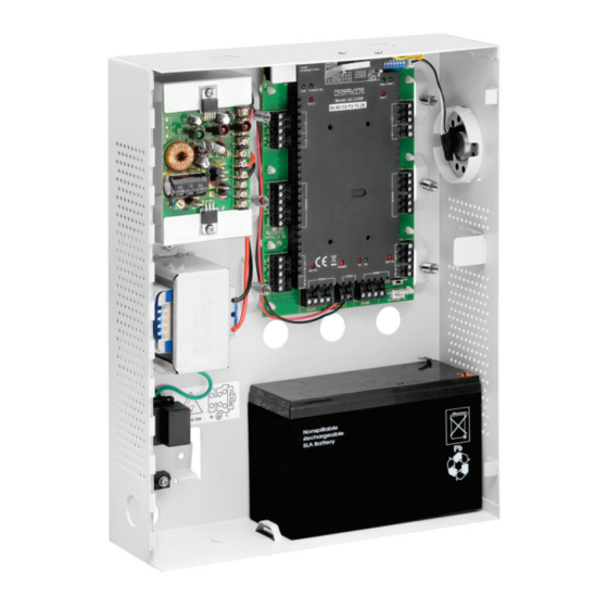
Page 18: Ac-215Ip Access Control Panel Diagram
AC-215IP Panel Setup AC-215IP Access Control Panel Diagram Figure 7 presents a complete view of the AC-215IP control panel’s PCB, including all connector buttons and LED schematics (not to scale). Figure 7: AC-215IP Wiring Communications AC-215IP Hardware Installation Manual... -
Page 19: Reader
When extending the cable distance, be careful with the color of the cable cover. Refer to the reader specifications for the maximum cable length (typically 150 m with an 18 AWG cable). Figure 8: Reader Wiring AC-215IP Hardware Installation Manual... -
Page 20: Input And Output Connections
Input and Output Connections Input and Output Connections This chapter describes the AC-215IP access control panel's input and output connections. Input Types There are four input types – Normally Open, Normally Closed, Normally Open Supervised 1 or 2 resistors, and Normally Closed Supervised 1 or 2 resistors. -
Page 21: Normally Closed Input Connection
Switch Open – Normal State: Loop resistance = 8.2K Switch Closed – Abnormal State: Loop resistance = 0 (short circuit). Open circuit across input terminals – Trouble State: Loop resistance = Infinite (open circuit). AC-215IP Hardware Installation Manual... -
Page 22: Normally Open Supervised Double Resistor Input Connection
Loop resistance = 10.4K Switch Closed – Abnormal State: Loop resistance = 2.2K Open circuit (infinite loop resistance) or short circuit (0 resistance) across input terminals – Trouble State Figure 12: Normally Open Supervised Input (Double Resistor) AC-215IP Hardware Installation Manual... -
Page 23: Normally Closed Supervised Single Resistor Input Connection
Switch Closed – Normal State: Loop resistance = 2.2K Switch Open – Abnormal State: Loop resistance = 10.4K Open circuit (Infinite loop resistance) or short circuit (0 resistance) across input terminals – Trouble State AC-215IP Hardware Installation Manual... -
Page 24: Inputs Description
Door 1 – IN 2A Double door controller: No general purpose inputs available General purpose inputs are suitable for most uses. For example, they might be used to detect tampering, to activate alarm sensors or for monitoring power supply failure. AC-215IP Hardware Installation Manual... -
Page 25: Outputs
Input and Output Connections Outputs Rosslare Security recommends the use of suppression diodes for all outputs that activate an inductive load. Door Lock There are two types of door locking devices: Fail open (fail secure) Fail close (fail safe) The following should be defined: Door 1 –... -
Page 26: Ac-215Ip Hardware Settings
AC-215IP Hardware Settings AC-215IP Hardware Settings Each AC-215IP panel controls an entrance. The behavior of the panel is controlled by DIP switch settings. Select the appropriate DIP switch setting to operate the panel as either a single door, a double door, or four doors (see Section 5.3). -
Page 27: Dip Switch Configuration
The Access control panel serial port baud rate, set in dip switches one and two, defines the communication speed for connecting with a PC in a network connection. The default baud rate is set to 9600 bits per second. 1 2 3 4 5 6 7 8 AC-215IP Hardware Installation Manual... -
Page 28: Access Control Panel Type
The default access control panel address is “1”. Figure 18: DIP Switch with Internal Network Address Setting 1 2 3 4 5 6 7 8 For successful communications, the DIP switch must match the address set in the AxTraxNG™ software. AC-215IP Hardware Installation Manual... -
Page 29: Table 5: Available Panel Addresses
AC-215IP Hardware Settings Table 5 displays the 32 address settings available: Table 5: Available Panel Addresses Address Switch 4 Switch 5 Switch 6 Switch 7 Switch 8 AC-215IP Hardware Installation Manual... -
Page 30: Communications
RS-232 Connection to the Computer Set the J1 switch to the RS-232 position. Table 6: RS-232 Connection Access Control Panel DB9 Connector DB25 Connector Pin 5 Pin 7 Pin 2 Pin 3 Pin 3 Pin 2 AC-215IP Hardware Installation Manual... -
Page 31: Rs-485 Connection To The Computer
The first panel is connected directly to the computer and a second panel connects to the first panel. Additional panels connect in the same way, one after another. Figure 19: Daisy Chaining AC-215IP #2 RS-485 AC-215IP #3 RS-485 AC-215IP Hardware Installation Manual... -
Page 32: Tcp/Ip Network Connection
When an access control panel network is connected using RS-485, up to 32 panels can be connected on each TCP/IP network. This means that one AC-215IP panel can support up to 31 AC- 215/225/425 panels. 6.2.1... -
Page 33: Modem Network Connection
Crossed 9-pin RS-232 cable (female jack on both sides) Rosslare MD-14 (RS-232 to RS-485 converter) 2 Rosslare MD-N33 (Modem to serial gateway) Rosslare AC-215IP panel 6.3.2 Prerequisites Before performing permanent modem installations, the modem that will be connected to the panel must be initialized from the computer running the AxTraxNG™... -
Page 34: Ac-215Ip Panel Connections
Connect the MD-N33 DB9 female jack to the MD-14 DB9 female jack. Connect the AC-215IP RS-485 outlet to the MD-14 4 wires cable. Make sure the J1 switch (on the AC-215IP) is set to RS-485 Mode. AC-215IP Hardware Installation Manual... -
Page 35: Limited Warranty
EMEDY OVERAGE In the event of a breach of warranty, ROSSLARE will credit Customer with the price of the Product paid by Customer, provided that the warranty claim is delivered to ROSSLARE by the Customer during the warranty period in accordance with the terms of this warranty. - Page 36 XCLUSIONS AND IMITATIONS ROSSLARE shall not be responsible or liable for any damage or loss resulting from the operation or performance of any Product or any systems in which a Product is incorporated. This warranty shall not extend to any ancillary...
- Page 37 Rosslare Security Products, Inc. support.cn@rosslaresecurity.com Southlake, TX, USA Toll Free: +1-866-632-1101 India Local: +1-817-305-0006 Fax: +1-817-305-0069 Rosslare Electronics India Pvt Ltd. support.na@rosslaresecurity.com Tel/Fax: +91 20 40147830 Mobile: +91 9975768824 Europe sales.in@rosslaresecurity.com Rosslare Israel Ltd. Rosh HaAyin, Israel Tel: +972 3 938-6838 Fax: +972 3 938-6830 support.eu@rosslaresecurity.com...
Need help?
Do you have a question about the AC-215IP and is the answer not in the manual?
Questions and answers