Rosslare AC-020 Hardware Installation And User's Manual
Access control system
Hide thumbs
Also See for AC-020:
- Hardware installation and user's manual (50 pages) ,
- Hardware installation and user's manual (61 pages)

Subscribe to Our Youtube Channel
Related Manuals for Rosslare AC-020


Summary of Contents for Rosslare AC-020
- Page 1 DOOR 2 DOOR 1 AC-020 Hardware Installation and User’s Guide 03/02...
- Page 2 Page 2 AC-020 03/02...
-
Page 3: Hardware Installation
Hardware Installation and User’s Guide for the AC-020 Access Control System DOOR 1 DOOR 2 Page 3 AC-020 03/02... - Page 4 Agreement. If you do not agree to the terms of this Agreement, promptly return the software package and other items that are part of this product in their original Page 4 AC-020 03/02...
- Page 5 Software, and the transferee agrees to be bound by the terms and conditions of this license. Upon any violation of any of the provisions of this Page 5 AC-020 03/02...
- Page 6 30 days for the software, whichever is longer. The remedies are void if failure of the software or hardware has resulted from abuse, accident or misapplication. Limitation of Liability. THE WARRANTIES SET FORTH IN THIS AGREEMENT REPLACE OTHER Page 6 AC-020 03/02...
- Page 7 DAMAGES. IN NO CASE SHALL ROSSLARE’S LIABILITY EXCEED THE ACTUAL MONEY PAID FOR THE PRODUCTS AT ISSUE. Because some jurisdictions allow implementation of limited warranties or liability for incidental, consequential, special, or indirect damages, the above limitation may not always Page 7 AC-020 03/02...
- Page 8 Consistent with 48. C.F.R. 12.212 and 48 C.F.R. 227.7202-1 through 227.7204-1 (June 1995), or any successor regulations, this software is provided to the terms and conditions herein. Contractor/ Manufacturer Rosslare Enterprises Ltd. Wang Road, Hong Kong Page 8 AC-020 03/02...
-
Page 9: Table Of Contents
Features and Concepts........21 Modes of Operation ........21 Changing the Modes of Operation....25 Events and Event Actions......28 AC-020 Programming Instructions ....31 Programming Menu Quick Reference Guide .31 Replacing a Lost Programming Code ...58 Replacing a Lost Normal / Secure Code ..59 Accessories .............60... - Page 10 Page 10 AC-020 03/02...
-
Page 11: Introduction
The AC-020 provides a higher level of security as the programmer is normally placed in a secure location while the reader sensors are remotely located outside the controlled premises. - Page 12 The AC-020 is capable of learning both PIN codes (keyboard based codes - 4 digits code) and Prox. Codes (codes received from proximity card reader). The Controller has two reader inputs, one for Door 1 and one for Door 2.
-
Page 13: Key Features
Key Features Here are some of the AC-020 system key features: • Supports two 26-Bit Wiegand compatible Readers • Three Modes of Operation Normal Mode Bypass Mode Secure Mode • Lock Strike Relay Output • Request to Exit (REX) button •... -
Page 14: Technical Specifications
12V DC Lead Acid Battery Up to 7AH recommended Outputs Lock Strike Relay 5A Relay Output: Lock Strike Power 12V DC constant Supply: voltage 1.2 A current limit Reader Power Voltage: 12V DC Supply: Max Current: 300mA Page 14 AC-020 03/02... -
Page 15: Mechanical Characteristics
-25°F to 145°F (-31°C Temperature: to 63°C) Operating Humidity: 0 to 95% (Non- Condensing) Mechanical Characteristics Dimensions: 5.3” (134mm) L x 3.4” (85mm) W x 1.2” (30mm) D (Fits US Gang Box) Weight: 0.5 lbs (220g) Page 15 AC-020 03/02... -
Page 16: Installation
Installation The AC-020 has been designed for easy installation. Only a few steps are required to install the controller. In this section you will learn how to mount the controller in your desired location. You will learn how to wire the controller to its power source, which includes attaching the controller to a rechargeable Lead Acid battery. -
Page 17: Mounting The Controller
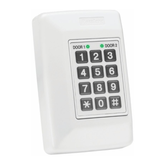
(Skip this step when attaching the AC-020 to a US Gang Box) Drill a hole for cables as indicated on the wiring template. Two hole sizes are shown to... - Page 18 Return and secure the front case using the security screw and security tool provided in the Installation Kit. have mechanically installed controller. Door 2 LED Door 1 LED DOOR 1 DOOR 2 3 x 4 Matrix Keypad Case Screw Page 18 AC-020 03/02...
-
Page 19: Power Wiring
16V AC (1.5A, 25VA) DOOR 1 DOOR 2 12V DC LEAD ACID BATTERY UP TO 7 AH RECOMMENDED Typical Lock and Option Wiring DOOR 1 DOOR 2 N.O. DOOR 1 REX 1 N.O. REX 2 DOOR 2 Page 19 AC-020 03/02... -
Page 20: Reader Wiring
Reader Wiring DOOR 1 DOOR 2 READER DOOR 1 +12V +12V 12V DC, Max. 300mA READER +12V +12V DOOR 2 12V DC, Max. 300mA Page 20 AC-020 03/02... -
Page 21: Features And Concepts
In this section you will learn about all the features that are programmable. They are the basic features of the AC-020 and can be programmed directly from controller’s programming keypad. - Page 22 The following examples show the LED status of Door 1 but are applicable to Door 2 as well. The AC-020 has three modes of operation Normal, Bypass, and Secure Mode. The three modes provide different levels of security. Normal Mode •...
- Page 23 Closed it will always be active. If the Lock Strike is defined as Normally Open it can be activated in the following ways: Pressing the REX button Valid Code (from an outside reader only using Prox. Code or Pin. Code) Page 23 AC-020 03/02...
- Page 24 Release Time. • In addition, it is possible to activate the Lock Strike in the following ways: Pressing the REX button Master Codes (from an outside reader only using Prox. Code or Pin. Code) Page 24 AC-020 03/02...
-
Page 25: Changing The Modes Of Operation
DOOR 1 / DOOR 2 DOOR 2 DOOR 1 LED will flash red Press the “*/#” key, respectively. • DOOR 1 / DOOR 2 DOOR 1 DOOR 2 LED will turn red • You are now in Secure Mode Page 25 AC-020 03/02... -
Page 26: Normal Mode
The controller is in Normal Mode • DOOR 1 / DOOR 2 DOOR 1 DOOR 2 GREEN LED is green Enter your Normal / Bypass PIN Code • DOOR 1 / DOOR 2 DOOR 1 DOOR 2 ORANGE will flash orange Page 26 AC-020 03/02... - Page 27 DOOR 1 DOOR 2 LED will flash green GREEN Press the “*/#” key, respectively. • DOOR 1 / DOOR 2 DOOR 1 DOOR 2 GREEN LED will turn green • You are now in Normal Mode Page 27 AC-020 03/02...
-
Page 28: Events And Event Actions
1 (default 0852) from external reader will not clear tamper because it is not permitted to open the door during this operation mode. However, applying the same code from the AC-020 keyboard will clear tamper output as well as opening Door 2 Lock Strike and stopping the siren (assuming no Door 1 tamper). - Page 29 REX button is pressed, the door will be unlocked until the REX button is released, plus the ”Lock Strike Release Time.” In this case the ”Lock Strike Relay” only begins its count down once the REX button has been released. Page 29 AC-020 03/02...
- Page 30 However, if the tamper condition at the other door exists, one is required to clear that tamper event as well, in order to stop the siren. Either way, the siren may stop on its own if the pre-programmed siren time has elapsed. Page 30 AC-020 03/02...
-
Page 31: Ac-020 Programming Instructions
AC-020’s features. Most of these features can be programmed via the AC-020’s programming keypad. The following pages describe how to program the AC-020 using the programming keypad. Topics in this section: •... - Page 32 Code 2 Changing Program Code Changing Normal/Secure Code Changing Normal/Bypass Code Changing Door Release Time Choosing Fail Secure/Fail Safe Operation Enrolling Proximity Cards or Keyboard Codes Deleting Proximity Cards or Keyboard Codes Returning to Default Factory Setting Page 32 AC-020 03/02...
- Page 33 Programming the AC-020 FOR DOOR 1 PROGRAM: Menu Function Initial Number Setting Changing Lock Strike 2580 Code 1 Changing Lock Strike 0000* Code 2 Changing Program Code 1234 Changing 3838 Normal/Secure Code Changing 0000* Normal/Bypass Code Changing Door Release 0004...
- Page 34 Normal/Bypass Code Changing Door Release 0004 Time Choosing Fail Secure/Fail Safe seconds) Operation Fail Secure Enrolling Proximity Cards or Keyboard Codes Deleting Proximity Cards or Keyboard Codes Returning to Default Factory Setting *0000 deletes a function Page 34 AC-020 03/02...
- Page 35 NOTE: You must be in NORMAL mode to program the AC-020. DOOR 1 / DOOR 2 LED will be green. Wrong or timed out entries will reset the controller to the NORMAL mode condition. To exit programming, press the “*/#” key for two seconds.
- Page 36 Entering Programming Mode To begin programming the controller’s settings, the AC-020 must first place into Programming Mode. You may only enter Programming mode from Normal mode, the controller does not permit entry to Programming Mode if the controller is in Bypass and Secure Mode.
- Page 37 Wrong entries may reset the controller back to Normal Operating Mode. While in Programming Mode if no key is pressed for 30 seconds the AC-020 will emit a long beep and return to Normal Operating Mode. A short press on the “*” or “#” key may also return the controller to Normal Operating Mode, accompanied by a long beep.
- Page 38 DOOR 2 GREEN will turn green • The DOOR 2 LED will be off Press 1 • The DOOR 1 LED DOOR 2 DOOR 1 GREEN will remain green • The DOOR 2 LED will turn red Page 38 AC-020 03/02...
- Page 39 Lock Strike Code 1. • You will hear 3 beeps • The system will return to NORMAL mode • The default Lock Strike Code 1 is 2580 for Door 1 and 0852 for Door 2 Page 39 AC-020 03/02...
- Page 40 DOOR 2 GREEN will turn green • The DOOR 2 LED will be off Press 2 • The DOOR 1 LED DOOR 1 DOOR 2 GREEN will remain green • The DOOR 2 LED will turn orange Page 40 AC-020 03/02...
- Page 41 ? ? ? code you wish to set as the new Programming Code. • You will hear 3 beeps • The system will return to Normal mode NOTE: There is no default code for Lock Strike Code 2. Page 41 AC-020 03/02...
- Page 42 GREEN will turn green • The DOOR 2 LED will turn off Press 3 • The DOOR 1 LED DOOR 1 DOOR 2 GREEN GREEN will remain green • The DOOR 2 LED will turn green Page 42 AC-020 03/02...
- Page 43 Programming Code NOTE: Programming Code cannot be erased. When trying to program code 0000, you will hear a long beep and the system will return to Normal operating mode. Page 43 AC-020 03/02...
- Page 44 DOOR 2 GREEN will turn green • The DOOR 2 LED will turn off Press 4 • The DOOR 1 LED DOOR 1 DOOR 2 will remain green GREEN • The DOOR 2 LED will flash red Page 44 AC-020 03/02...
- Page 45 Normal/Secure change code. • You will hear 3 beeps • The system will return to Normal mode (Default Secure code is 3838 for Door 1 and 8383 for Door 2.) Page 45 AC-020 03/02...
- Page 46 GREEN ORANGE will remain green • The DOOR 2 LED will flash orange NOTE: The Normal / Bypass Code also controls the Chime function for the AC-020. You may set the code to 4 available options. Page 46 AC-020 03/02...
- Page 47 Chime • Enter a 4-digit code ending with the digit 0. The Bypass mode is enabled and the Chime function is disabled. • You will hear 3 beeps • The system will return to Normal mode Page 47 AC-020 03/02...
- Page 48 0. The Bypass mode and the Chime function are enabled for both Normal mode and Bypass mode. • You will hear 3 beeps • The system will return to Normal mode NOTE: No default Bypass code exists. Page 48 AC-020 03/02...
- Page 49 GREEN will turn green • The DOOR 2 LED will turn off Press 6 • The DOOR 1 LED DOOR 1 DOOR 2 GREEN GREEN will remain green • The DOOR 2 LED will flash green Page 49 AC-020 03/02...
- Page 50 0512 means fail secure with a 5- minute tamper alarm sound time and a 12 second door release.) • You will hear 3 beeps. • The system will return to Normal mode. • Default door open time is 4 seconds. Page 50 AC-020 03/02...
- Page 51 NOTE: Each proximity card is unique and can only be assigned to one slot at a time. If an unassigned proximity card is enrolled at an occupied slot, the AC-020 will generate a long beep and wait for another slot number to be entered. The...
- Page 52 • The DOOR 2 LED will stop flashing To enroll another card, enter the 3-digit slot code you wish to assign to the next employee. • The DOOR 2 LED will start flashing Page 52 AC-020 03/02...
- Page 53 “*” or “#” key. • You will hear a long beep • The AC-020 will return to Normal mode NOTE: If the programming period times out before you press the “*” or “#” key, the controller will emit a long beep...
- Page 54 DOOR 2 GREEN will turn green • The DOOR 2 LED will turn off Press 8 • The DOOR 1 LED DOOR 1 DOOR 2 ORANGE will turn orange • The DOOR 2 LED will turn red Page 54 AC-020 03/02...
- Page 55 Then, if you wish to delete a lost or stolen employee code from the system, you can identify the card number from your record. Page 55 AC-020 03/02...
- Page 56 DOOR 1 DOOR 2 GREEN will turn green • The DOOR 2 LED will turn off Press 0 • The DOOR 1 LED DOOR DOOR 2 will flash red • The DOOR 2 LED will flash red Page 56 AC-020 03/02...
- Page 57 Doing so will erase all of the employee codes from the memory special codes will return to their default values. preprogrammed cards, PIN codes and special codes will have to be preprogrammed from the beginning. Page 57 AC-020 03/02...
-
Page 58: Replacing A Lost Programming Code
Programming Mode so that you may create a new Programming Code. The AC-020 must be in Normal Mode otherwise this will not work. Make sure that the DOOR 1 / DOOR 2 LED is green before proceeding. -
Page 59: Replacing A Lost Normal / Secure Code
Normal Mode so that you may program a new Normal / Secure Code. The AC-020 must be in Secure Mode otherwise this will not work. Make sure that the DOOR 1 / DOOR 2 LED is red before proceeding. -
Page 60: Accessories
PIN Readers AY-C09 / AY-D09 • For indoor use • Slim Stylish Design (Mullion) • Includes LED Indicator • Audible Buzzer Indicator • Built in Tamper (w/ Rosslare Controllers) • Includes Bell Button (w/ Rosslare Controllers) Page 60 AC-020 03/02... - Page 61 RF Modulation: ASK at 125 kHz • For indoor use • Slim Stylish Design (USA Gang Box) • Bi-Color Light Indicator • Audible Buzzer Indicator • Built in Tamper (w/ Rosslare Controllers) • Includes Bell Button (w/ Rosslare Controllers) Page 61 AC-020 03/02...
- Page 62 • RF Modulation: ASK at 125 kHz • For indoor use • Slim Stylish Design (USA Gang Box) • Bi-Color Light Indicator • Audible Buzzer Indicator (w/ Rosslare Controllers) • Built in Tamper (w/ Rosslare Controllers) Page 62 AC-020 03/02...
- Page 63 RF Modulation: ASK at 125 kHz • For outdoor use • Slim Stylish Design (UK or USA Gang Box, Mullion) • Bi-Color Light Indicator • Includes LED Control Input • Audible Buzzer Indicator • Built in Tamper Output Page 63 AC-020 03/02...
- Page 64 RF Modulation: ASK at 125 kHz • For indoor use • Slim Stylish Design (USA Gang Box) • Bi-Color Light Indicator • Audible Buzzer Indicator • Built in Tamper (w/ Rosslare Controllers) • Includes Bell Button (w/ Rossalare Controllers) Page 64 AC-020 03/02...
- Page 65 For Outdoor Use (Water Proof) • Frequency: 433MHz • Slim Stylish Design (Mullion) • Bi-Color LED Indicator • LED Control • Audible Buzzer Indicator • Size: 145mm x 43mm x 20mm • Used with SA-26 Wireless Remote Page 65 AC-020 03/02...
- Page 66 Page 66 AC-020 03/02...
-
Page 67: Technical Support
(39) 0382 24800 Fax: (39) 0382 24800 E-mail: marco.rogante@tin.it rosslarect@aol.com United States and Canada: Rosslare NAPDC 200 East Howard Street, Suite 238, Des Plaines, IL 60018 Tel: (847) 827 6330 Fax: (847) 827 6433 E-mail: support@rosslare.net Page 67 AC-020 03/02... - Page 70 www.rosslare.com.hk www.rosslare.com.hk www.rosslare.com.hk...
Need help?
Do you have a question about the AC-020 and is the answer not in the manual?
Questions and answers