Rosslare AC-425 Hardware Installation And User's Manual
Hide thumbs
Also See for AC-425:
- Hardware installation and user's manual (47 pages) ,
- Hardware installation and user's manual (40 pages)
Table of Contents
Advertisement
Quick Links
¡Error! Utilice la ficha Inicio para aplicar TOA Heading al texto que desea que
aparezca aquí.
1. Introduction ................................................................... 8
1.1
Features .................................................................................................................... 10
1.2
AxSraxNG™ ................................................................................................................ 10
1.3
Compatible Readers ................................................................................................... 11
2. Technical Specifications ............................................... 12
3. AC-425 Panel Setup ..................................................... 14
3.1
Inputs Wiring - Non-Supervised Inputs ..................................................................... 15
3.2
Inputs Wiring - Supervised Inputs ............................................................................ 15
3.3
Outputs Wiring ........................................................................................................... 15
3.4
Power Supply ............................................................................................................. 17
3.5
Readers...................................................................................................................... 18
3.6
MD-IO84 ................................................................................................................... 19
3.7
MD-D04 .................................................................................................................... 19
4. Input and Output Connections ...................................... 21
4.1
Input Types ................................................................................................................. 21
4.2
Inputs Description ...................................................................................................... 26
4.3
Outputs ...................................................................................................................... 27
4.4
Card Readers and Keypads......................................................................................... 28
5. AC-425 Hardware Settings ........................................... 30
5.1
DIP Switch Configuration .......................................................................................... 32
5.2
AC-425 Panel Baud Rate .......................................................................................... 32
5.3
AC-425 Panel Type .................................................................................................. 33
5.4
AC-425 Panel Address ............................................................................................. 33
6. Communications .......................................................... 36
6.1
Serial Network Connection ........................................................................................36
Table of Contents
iii
Advertisement
Table of Contents

Related Manuals for Rosslare AC-425


Summary of Contents for Rosslare AC-425
-
Page 1: Table Of Contents
Features ........................10 AxSraxNG™ ........................ 10 Compatible Readers ....................11 2. Technical Specifications ..........12 3. AC-425 Panel Setup ............. 14 Inputs Wiring – Non-Supervised Inputs ..............15 Inputs Wiring – Supervised Inputs ................15 Outputs Wiring ......................15 Power Supply ......................17 Readers........................ - Page 2 ¡Error! Utilice la ficha Inicio para aplicar TOA Heading al texto que desea que aparezca aquí. TCP/IP Network Connection ..................37 Modem Network Connection ..................38 A. Limited Warranty ............40 AC-425 Hardware Installation and User Guide...
- Page 3 Figure 18: DIP Switch with Internal Network Address Setting ..........34 Figure 19: Daisy Chaining ......................37 Figure 20: MD-N32 Configuration connecting a single panel ..........38 Figure 21: Connecting Multiple Access control panels with AC-425 ........38 Figure 22: Remote Site Modem Configuration................39 AC-425 Hardware Installation and User Guide...
- Page 4 ¡Error! Utilice la ficha Inicio para aplicar TOA Heading al texto que desea que aparezca aquí. List of Tables No table of figures entries found. AC-425 Hardware Installation and User Guide...
- Page 5 ROSSLARE ENTERPRISES LIMITED and/or its related companies and/or subsidiaries’ (hereafter: "Rosslare") exclusive warranty and liability is limited to the warranty and liability statement provided in an appendix at the end of this document. ...
-
Page 6: Introduction
The state-of-the-art dual/quad door AC-425 networked access controller is the backbone of medium scale security systems handling up to 30,000 users and 8184 doors. Each AC-425 Access Control Unit (ACU) supports four readers (In/Out) of various formats including standard Wiegand 26-bit. Installations can also have one reader per door. -
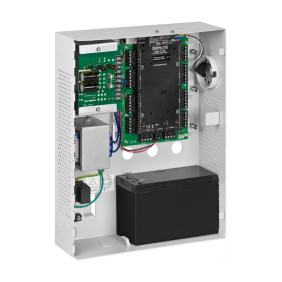
Page 7: Figure 1: Ac-425 Panel
¡Error! Utilice la ficha Inicio para aplicar Heading 1 al texto que desea que aparezca aquí. Figure 1: AC-425 panel AC-425 Hardware Installation and User Guide... -
Page 8: Features
¡Error! Utilice la ficha Inicio para aplicar Heading 1 al texto que desea que aparezca aquí. Features The AC-425 is a powerful and adaptable access control solution with a range of powerful features. Controls 1 to 4 doors (DIP switch controlled) or 1 to 8 doors when the optional MD- D04 is installed ... -
Page 9: Axsraxng
1.2.3 Fingerprint Recognition AxSraxNG™ can share user details with Rosslare's BioTrax software system. The BioTrax system can then download all selected user information to an AYC-W6500 fingerprint reader. Fingerprint recognition was not evaluated by UL. -
Page 10: Technical Specifications
Molex and Terminal Block TCP/IP On-board RJ-45 connector Internal IP module Speed Options 9600, 19200, 57600, 115200 bps Environmental Characteristics Operating Temperature Range 32°F – 120°F (0°C – 49°C) Operating Humidity 0 – 85% (non-condensing) AC-425 Hardware Installation and User Guide... - Page 11 PS-33 Power Supply Indication Tamper Output Indicates faulty power (open collector) PS-33 Power LEDs Power In (AC) Main power Green LED1 Power Out (DC) Low voltage Red LED2 Low Battery Backup battery low voltage Red LED3 AC-425 Hardware Installation and User Guide...
-
Page 12: Ac-425 Panel Setup
¡Error! Utilice la ficha Inicio para aplicar Heading 1 al texto que desea que aparezca aquí. AC-425 Panel Setup Each AC-425 panel controls 2 or 4 doors (up to 8 doors with MD-D04). The panels connect together in a network and are controlled by a central server computer, running the AxSraxNG™ software system. -
Page 13: Inputs Wiring - Non-Supervised Inputs
Figure 3: Inputs Wiring – Non-supervised Inputs Inputs Wiring – Supervised Inputs When wiring the AC-425 for supervised inputs, resistors should be placed on the input switch and not on the terminal block. For more details, refer to Chapter 4. -
Page 14: Figure 4: Door Lock - Failed Close
¡Error! Utilice la ficha Inicio para aplicar Heading 1 al texto que desea que aparezca aquí. Figure 4: Door Lock – Failed Close AC-425 Hardware Installation and User Guide... -
Page 15: Power Supply
Figure 5: Door Lock – Failed Open Power Supply The following diagram illustrates wiring between the PS-33 power supply and the AC-425. It is recommended to add a 12 VDC lead acid backup battery if the main power supply fails. -
Page 16: Readers
¡Error! Utilice la ficha Inicio para aplicar Heading 1 al texto que desea que aparezca aquí. Figure 6: Wiring Between PS-33 and AC-425 Readers Proximity & keypad readers are supplied with a limited cable. The color of the cable cover represents the cable’s function according to Wiegand standards. -
Page 17: Md-Io84
The MD-D04 is an optional reader expansion board that adds 4 readers, 4 relay outputs and 4 supervised inputs to the Access Control Panel. Attach the MD-D04 to the AC-425's expansion slot, as marked in red in Figure 8. For more information, see the MD-D04 Installation and User Guide. -
Page 18: Figure 8: Connector Location For Md-Io84 Or Md-D04 Expansions
¡Error! Utilice la ficha Inicio para aplicar Heading 1 al texto que desea que aparezca aquí. Figure 8: Connector Location for MD-IO84 or MD-D04 Expansions AC-425 Hardware Installation and User Guide... -
Page 19: Input And Output Connections
¡Error! Utilice la ficha Inicio para aplicar Heading 1 al texto que desea que aparezca aquí. Input and Output Connections This chapter describes the AC-425 access control panel's input and output connections. Input Types There are four input types: ... -
Page 20: Figure 9: Normally Open Input Connection
Switch Open – Normal State: Loop resistance = 8.2 kΩ Switch Closed – Abnormal State: Loop resistance = 0 (short circuit) Open circuit across input terminals – Trouble State: Loop resistance = Infinite (open circuit). AC-425 Hardware Installation and User Guide... -
Page 21: Figure 11: Normally Open Supervised Input (Single Resistor)
Figure 11: Normally Open Supervised Input (Single Resistor) 4.1.4 Normally Open Supervised Double EOL Resistor Input Connection Connect a 2.2 kΩ resistor in series to the input switch contacts. Connect an 8.2 kΩ resistor parallel to the input switch contacts. AC-425 Hardware Installation and User Guide... -
Page 22: Figure 12: Normally Open Supervised Input (Double Resistor)
Switch Closed – Normal State: Loop resistance = 2.2 kΩ Switch Open – Abnormal State: Loop resistance = Infinite (open circuit) Short circuit across input terminals – Trouble State: Loop resistance = 0 (short circuit) AC-425 Hardware Installation and User Guide... -
Page 23: Figure 13: Normally Closed Supervised Input (Single Resistor)
Switch Open – Abnormal State: Loop resistance = 10.4 kΩ Open circuit (infinite loop resistance) or short circuit (0 resistance) across input terminals – Trouble State Figure 14: Normally Closed Supervised Input (Double Resistor) AC-425 Hardware Installation and User Guide... -
Page 24: Inputs Description
The following should be defined: Scenario Setting Two readers per door Door 1 – IN3 Door 1 – IN4 AC-425 Hardware Installation and User Guide... -
Page 25: Outputs
MD-IO84 IN5 to IN12 MD-D04 IN5 to IN8 except the dedicated inputs Outputs Rosslare Security recommends the use of suppression diodes for all outputs that activate an inductive load. 4.3.1 Door Lock There are two types of door locking devices: ... -
Page 26: Card Readers And Keypads
One readers per door Door 1 – Reader 1 IN/OUT Door 2 – Reader 2 IN/OUT Door 3 – Reader 3 IN/OUT Door 4 – Reader 4 IN/OUT When using the MD-D04, the following should be defined: AC-425 Hardware Installation and User Guide... - Page 27 "Card and PIN" secure mode. While this mode is in force, users must enter a PIN on the keypad immediately after entering the card. The controller activates the LED control for 2 seconds when an access granted event occurs. AC-425 Hardware Installation and User Guide...
-
Page 28: Ac-425 Hardware Settings
¡Error! Utilice la ficha Inicio para aplicar Heading 1 al texto que desea que aparezca aquí. AC-425 Hardware Settings Each AC-425 panel controls an entrance. The behavior of the panel is controlled by DIP switch settings. Select the appropriate DIP switch setting to operate the panel as either a single door, a double door, or four doors (see Section 5.3). - Page 29 (IN 4) Door5 Request to exit (IN 5) Door6 Request to exit (IN 6) Door7 Request to exit (IN 7) Door8 Request to exit (IN 8) Readers Reader1 (Door1 IN/OUT) Reader2 (Door2 OUT /IN) AC-425 Hardware Installation and User Guide...
-
Page 30: Dip Switch Configuration
AC-425 Panel Baud Rate The AC-425 panel serial port baud rate, set in DIP switches 1 and 2, defines the communication speed for connecting with a PC in a network connection. The default baud rate is set to 9600 bits per second. -
Page 31: Ac-425 Panel Type
AC-425 Panel Type The AC-425 panel type is defined using the third DIP switch. There are two panel types: a panel with one reader per each door or a panel with two readers per each door. This DIP switch setting influences the number of readers per door in the panel. -
Page 32: Figure 18: Dip Switch With Internal Network Address Setting
For successful communications, the DIP switch must match the address set in the AxSraxNG™ software. The following table displays the 32 address settings available: Address Switch 4 Switch 5 Switch 6 Switch 7 Switch 8 AC-425 Hardware Installation and User Guide... - Page 33 Address Switch 4 Switch 5 Switch 6 Switch 7 Switch 8 The AC-425 panel address is defined in the AxSraxNG™ software. The DIP switch and the software must be set to the same address. AC-425 Hardware Installation and User Guide...
-
Page 34: Communications
Pin 2 The RS-232 connects the computer to only a single AC-425 panel. The distance between the computer and the AC-425 panel must be no more than 150 feet (50 meters). If the baud rate is increased to 57600 or beyond, the distance must be no more than 30 feet (10 meters). -
Page 35: Ac-425 Hardware Installation And User Guide
The serial port used to control the access control panel is assigned within the AxSraxNG™ software. The AC-425 panel supports a 2-wire RS-485 interface. Using the RS-485 interface can increase the distance between server and panels up to 4,000 feet. -
Page 36: Figure 20: Md-N32 Configuration Connecting A Single Panel
The devices can be connected to a TCP/IP network using any valid network address. Use a TCP/IP connection when a LAN network already exists and the long RS-485 network is not required. The following schematic illustrates the connection of a single AC-425 to a computer via a LAN network. -
Page 37: Figure 22: Remote Site Modem Configuration
Connect the MD-N33 DB9 female jack to the MD-14 DB9 female jack. Connect the AC-425 RS-485 outlet to the MD-14 4 wires cable. Make sure the J1 switch (on the AC-425) is set to RS-485 Mode. AC-425 Hardware Installation and User Guide... - Page 38 EMEDY OVERAGE In the event of a breach of warranty, ROSSLARE will credit Customer with the price of the Product paid by Customer, provided that the warranty claim is delivered to ROSSLARE by the Customer during the warranty period in accordance with the terms of this warranty.
- Page 39 XCLUSIONS AND IMITATIONS ROSSLARE shall not be responsible or liable for any damage or loss resulting from the operation or performance of any Product or any systems in which a Product is incorporated. This warranty shall not extend to any ancillary equipment not furnished by ROSSLARE, which is attached to or used in conjunction with a Product, nor to any Product that is used with any ancillary equipment, which is not furnished by ROSSLARE.
Need help?
Do you have a question about the AC-425 and is the answer not in the manual?
Questions and answers