Rosslare AC-425 Hardware Installation And User's Manual
Professional scalable networked access controller
Hide thumbs
Also See for AC-425:
- Hardware installation and user's manual (47 pages) ,
- Hardware installation and user's manual (39 pages)

Subscribe to Our Youtube Channel
Related Manuals for Rosslare AC-425


Summary of Contents for Rosslare AC-425
- Page 1 AC-425 Professional Scalable Networked Access Controller Hardware Installation and User Guide Models: AC-425 AC-425IP...
- Page 2 ROSSLARE. ROSSLARE reserves the right to revise and change this document at any time, without being obliged to announce such revisions or changes beforehand or after the fact.
-
Page 3: Table Of Contents
1.1.3 Fingerprint Recognition ................10 Compatible Readers ................10 2. Technical Specifications ..........11 3. AC-425 Panel Setup ............13 Inputs Wiring – Non-Supervised Inputs ..........14 Inputs Wiring – Supervised Inputs ............. 15 Outputs Wiring ................. 15 Power Supply ..................17 AC-425 Wiring Communications ............ - Page 4 Outputs .................... 26 4.3.1 Door Lock ....................26 Card Readers and Keypads ..............27 5. AC-425 Hardware Settings ..........29 DIP Switch Configuration ..............31 AC-425 Panel Baud Rate ..............32 AC-425 Panel Type ................32 AC-425 Panel Address ..............33 6.
- Page 5 Figure 19: DIP Switch with Internal Network Address Setting ......33 Figure 20: Daisy Chaining ................36 Figure 21: MD-N32 Configuration Connecting a Single Panel ....... 37 Figure 22: Connecting Multiple Access Control Panels with AC-425 ..... 38 AC-425 Hardware Installation and User Manual...
- Page 6 List of Tables List of Tables Table 1: Possible Hardware Settings .............. 29 Table 2: Switch Baud Rates ................32 Table 3: Available Panel Addresses ............... 33 Table 4: RS-232 Connection ................. 35 AC-425 Hardware Installation and User Manual...
- Page 7 ROSSLARE exclusive warranty and liability is limited to the warranty and liability statement provided in an appendix at the end of this document. ...
-
Page 8: Introduction
Introduction Introduction In this manual, unless otherwise stated, “AC-425” refers to both the regular AC-425 and the AC-425IP moels. The AC-425 access control panel is a state-of-the-art networked access controller, employing the latest technology to meet the requirements of the market. -
Page 9: Axtraxng
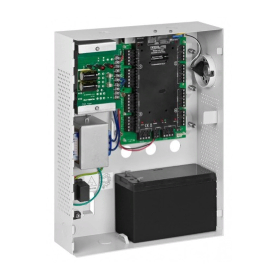
Introduction Figure 1 shows the layout of the AC-425 panel. Figure 1: AC-425 Panel AxTraxNG The AxTraxNG software system is custom designed to set up, manage, and supervise all aspects of an access panel network. It offers the following capabilities:... -
Page 10: Client-Server Structure
1.1.3 Fingerprint Recognition AxTraxNG can share user details with Rosslare's BioTrax software system. The BioTrax system can then download all selected user information to an AYC- W6500 fingerprint reader. -
Page 11: Technical Specifications
TCP/IP (AC-425IP model only) Onboard RJ-45 connector Internal IP module Speed Options 9600, 19200, 57600, 115200 bps Environmental Characteristics Operating Temperature Range 0°C to 49°C (32°F to 120°F) Operating Humidity Range 0 to 85% (non-condensing) AC-425 Hardware Installation and User Manual... - Page 12 PS-33 Power Supply Indication Tamper Output Indicates faulty power (open collector) PS-33 Power LEDs Power In (AC) Main power Green LED1 Power Out (DC) Low voltage Red LED2 Low Battery Backup battery low voltage Red LED3 AC-425 Hardware Installation and User Manual...
-
Page 13: Ac-425 Panel Setup
AC-425 Panel Setup AC-425 Panel Setup Each AC-425 panel controls 2 or 4 doors (up to 8 doors with MD-D04). The panels connect together in a network and are controlled by a central server computer, running the AxTraxNG software system. -
Page 14: Inputs Wiring - Non-Supervised Inputs
AC-425 Panel Setup Inputs Wiring – Non-Supervised Inputs Figure 3 presents a detailed view of the non-supervised inputs and their connection options. Figure 3: Inputs Wiring – Non-supervised Inputs AC-425 Hardware Installation and User Manual... -
Page 15: Inputs Wiring - Supervised Inputs
AC-425 Panel Setup Inputs Wiring – Supervised Inputs When wiring the AC-425 for supervised inputs, resistors should be placed on the input switch and not on the terminal block. For more details, refer to Chapter 4. Outputs Wiring Figure 4 and Figure 5 illustrate wiring for two main types of 12 VDC electrical release mechanisms. -
Page 16: Figure 5: Door Lock - Failed Open
AC-425 Panel Setup Figure 5: Door Lock – Failed Open AC-425 Hardware Installation and User Manual... -
Page 17: Power Supply
AC-425 Panel Setup Power Supply Figure 6 illustrates wiring between the PS-33 power supply and the AC-425. It is recommended to add a 12 VDC lead acid backup battery if the main power supply fails. If the main output is 12 VDC, wire it to the PS-33, whose load ratings are 1.5 A/0.9 A/0.3 A;... -
Page 18: Ac-425 Wiring Communications
(Figure 8). When extending the cable distance, be careful with the color of the cable cover. Refer to the reader specifications for the maximum cable length (typically 150 m with an 18 AWG cable). AC-425 Hardware Installation and User Manual... -
Page 19: Md-Io84
The MD-D04 is an optional reader expansion board that adds 4 readers, 4 relay outputs and 4 supervised inputs to the Access Control Panel. Attach the MD- D04 to the AC-425's expansion slot, as marked in red in Figure 9. For more information, see the MD-D04 Installation and User Guide. -
Page 20: Input And Output Connections
Input and Output Connections Input and Output Connections This chapter describes the AC-425 access control panel's input and output connections. Input Types There are four input types: Normally Closed (N.C.) Normally Open (N.O.) Single EOL resistor ... -
Page 21: Normally Closed Input Connection
Connect an 8.2 kΩ resistor in parallel to the input switch contacts. A Normally Open Supervised Input has 3 states: Switch Open – Normal State: Loop resistance = 8.2 kΩ Switch Closed – Abnormal State: Loop resistance = 0 (short circuit) AC-425 Hardware Installation and User Manual... -
Page 22: Normally Open Supervised Double Eol Resistor Input Connection
Switch Closed – Abnormal State: Loop resistance = 2.2 kΩ Open circuit (infinite loop resistance) or short circuit (0 resistance) across input terminals – Trouble State Figure 13: Normally Open Supervised Input (Double Resistor) AC-425 Hardware Installation and User Manual... -
Page 23: Normally Closed Supervised Single Eol Resistor Input Connection
Loop resistance = 2.2 kΩ Switch Open – Abnormal State: Loop resistance = 10.4 kΩ Open circuit (infinite loop resistance) or short circuit (0 resistance) across input terminals – Trouble State AC-425 Hardware Installation and User Manual... -
Page 24: Inputs Description
One reader per door Door 1 – IN1 Door 2 – IN2 Door 3 – IN3 Door 4 – IN4 Door 5 – IN5 Door 6 – IN6 Door 7 – IN7 Door 8 – IN8 AC-425 Hardware Installation and User Manual... -
Page 25: Door Monitor Input
General purpose inputs functions when using MD-IO84 or MD-D04: Unit Expansions MD-IO84 IN5 to IN12 MD-D04 IN5 to IN8 except the dedicated inputs AC-425 Hardware Installation and User Manual... -
Page 26: Outputs
Input and Output Connections Outputs Rosslare Security recommends the use of suppression diodes for all outputs that activate an inductive load. 4.3.1 Door Lock There are two types of door locking devices: Fail open (fail secure) Fail close (fail safe) -
Page 27: Card Readers And Keypads
Door 3 – Reader 3 IN/OUT Door 4 – Reader 4 IN/OUT Door 5 – Reader 5 IN/OUT Door 6 – Reader 6 IN/OUT Door 7 – Reader 7 IN/OUT Door 8 – Reader 8 IN/OUT AC-425 Hardware Installation and User Manual... - Page 28 "Card and PIN" secure mode. While this mode is in force, users must enter a PIN on the keypad immediately after entering the card. The controller activates the LED control for 2 seconds when an access granted event occurs. AC-425 Hardware Installation and User Manual...
-
Page 29: Ac-425 Hardware Settings
AC-425 Hardware Settings AC-425 Hardware Settings Each AC-425 panel controls an entrance. The behavior of the panel is controlled by DIP switch settings. Select the appropriate DIP switch setting to operate the panel as either a single door, a double door, or four doors (see Section 5.3). - Page 30 Door2 Lock output (OUT 2) Door3 Lock output (OUT 3) Door4 Lock output (OUT 4) Door5 Lock output (OUT 5) Door6 Lock output (OUT 6) Door7 Lock output (OUT 7) Door8 Lock output (OUT 8) AC-425 Hardware Installation and User Manual...
-
Page 31: Dip Switch Configuration
Reader8 (Door8 OUT /IN) DIP Switch Configuration The AC-425 panel DIP switch controls a number of operating parameters, including the device address and baud rates for serial communication. Figure 16: DIP Switch 1 2 3 4 5 6 7 8... -
Page 32: Ac-425 Panel Baud Rate
AC-425 Panel Baud Rate The AC-425 panel serial port baud rate, set in DIP switches 1 and 2, defines the communication speed for connecting with a PC in a network connection. The default baud rate is set to 9600 bits per second. -
Page 33: Ac-425 Panel Address
For successful communications, the DIP switch must match the address set in the AxTraxNG software. Table 3 displays the 32 address settings available: Table 3: Available Panel Addresses Address Switch 4 Switch 5 Switch 6 Switch 7 Switch 8 AC-425 Hardware Installation and User Manual... - Page 34 Address Switch 4 Switch 5 Switch 6 Switch 7 Switch 8 The AC-425 panel address is defined in the AxTraxNG software. The DIP switch and the software must be set to the same address. AC-425 Hardware Installation and User Manual...
-
Page 35: Communications
AxTraxNG server. The default baud rate is 9600 bps for direct connection to the computer. When using an RS-232 connector, only one AC-425 panel can be linked to each communication port on the computer. Use an RS-485 if you wish to connect more than one panel on one communication port. -
Page 36: Rs-485 Connection To The Computer
6.1.2 RS-485 Connection to the Computer Set the J1 switch to the RS-485 position. Up to 32 access control panels (AC-425, AC-225, AC-215, or AC-525) can be linked together and connected to a single communication port on the computer. Use the RS-485 interface for situations where there are multiple controllers connected. -
Page 37: Tcp/Ip Network Connection
TCP/IP network. The connection settings are controlled within the AxTraxNG Client software. AC-425 panels connect to the TCP/IP network (LAN or WAN) directly, using an onboard network module. When an access control panel network is connected using RS-485, up to 32 panels can be connected on each TCP/IP network. -
Page 38: Figure 22: Connecting Multiple Access Control Panels With Ac-425
Communications Figure 22: Connecting Multiple Access Control Panels with AC-425 Before connecting a panel by TCP/IP connection for the first time, the AxTraxNG software must configure the device. Settings are then stored in non- volatile memory on the device (see the AxTraxNG Software Manual). -
Page 39: Limited Warranty
The full ROSSLARE Limited Warranty Statement is available in the Quick Links section on the ROSSLARE website at www.rosslaresecurity.com. Rosslare considers any use of this product as agreement to the Warranty Terms even if you do not review them. AC-425 Hardware Installation and User Manual... - Page 40 Southlake, TX, USA support.cn@rosslaresecurity.com Toll Free: +1-866-632-1101 Local: +1-817-305-0006 India Fax: +1-817-305-0069 support.na@rosslaresecurity.com Rosslare Electronics India Pvt Ltd. Tel/Fax: +91 20 40147830 Europe Mobile: +91 9975768824 sales.in@rosslaresecurity.com Rosslare Israel Ltd. Rosh HaAyin, Israel Tel: +972 3 938-6838 Fax: +972 3 938-6830 support.eu@rosslaresecurity.com...
Need help?
Do you have a question about the AC-425 and is the answer not in the manual?
Questions and answers