Rosslare AC-425 Hardware Installation And User's Manual
Multi-advanced scalable networked access controller
Hide thumbs
Also See for AC-425:
- Hardware installation and user's manual (40 pages) ,
- Hardware installation and user's manual (39 pages)

Subscribe to Our Youtube Channel
Related Manuals for Rosslare AC-425


Summary of Contents for Rosslare AC-425
- Page 1 AC-425 Multi-Advanced Scalable Networked Access Controller Hardware Installation and User Guide November 2011...
-
Page 3: Table Of Contents
Outputs ..................26 Card Readers and Keypads ............27 AC-425 Hardware Settings ........... 30 DIP Switch Configuration ............32 AC-425 Panel Baud Rate ............33 AC-425 Panel Type ..............34 AC-425 Panel Address ............... 34 Communications ............37 Serial Network Connection ............37 TCP/IP Network Connection ............ - Page 4 ROSSLARE. ROSSLARE reserves the right to revise and change this document at any time, without being obliged to announce such revisions or changes beforehand or after the fact.
-
Page 5: Introduction
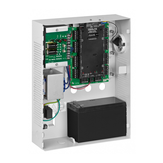
It provides seamless integration with Rosslare's range of RFID proximity, PIN, PIN & PROX, smartcard and biometric readers with Rosslare’s selection of RFID credentials. The AC-425 is ready for installation with a mountable & lockable metal enclosure integrated with transformer, power supply/charger, sounder and control board. - Page 6 Introduction Figure 1: AC-425 panel Page 6 AC-425 Hardware Installation and User Guide...
-
Page 7: Features
Introduction Features The AC-425 is a powerful and adaptable access control solution with a range of powerful features. Controls 1 to 4 doors (DIP switch controlled) or 1 to 8 doors • when the optional MD-D04 is installed Four IN/OUT readers, with tamper switch and LED control •... - Page 8 CCTV systems, and elevator controls. AxTraxNG™ can also define a selected set of operations, which are defined in configurable links, when a panel registers a specified user or group of users. This can be useful, for Page 8 AC-425 Hardware Installation and User Guide...
-
Page 9: Compatible Readers
1.2.3 Fingerprint Recognition AxTraxNG™ can share user details with Rosslare's BioTrax software system. The BioTrax system can then download all selected user information to an AYC-W6500 fingerprint reader. Note: Fingerprint recognition was not evaluated by UL. -
Page 10: Technical Specifications
Molex and Terminal Block TCP/IP On-board RJ-45 connector Internal IP module Speed Options 9600, 19200, 57600, 115200 bps Environmental Characteristics Operating Temperature 32°F – 120°F (0°C – 49°C) Range Operating Humidity 0 – 85% (non-condensing) Page 10 AC-425 Hardware Installation and User Guide... - Page 11 Tamper Output Indicates faulty power (open collector) PS-33 Power LEDs Power In (AC) Main power Green LED1 Power Out (DC) Low voltage Red LED2 Low Battery Backup battery low voltage Red LED3 AC-425 Hardware Installation and User Guide Page 11...
-
Page 12: Ac-425 Panel Set-Up
AC-425 Panel Set-Up 3. AC-425 Panel Set-Up Each AC-425 panel controls 2 or 4 doors (up to 8 doors with MD-D04). The panels connect together in a network and are controlled by a central server computer, running the AxTraxNG™ software system. -
Page 13: Inputs Wiring - Non-Supervised Inputs
AC-425 Panel Set-Up Note: Bushings are needed for any conductors leaving the enclosure through the provided openings. Inputs Wiring – Non-Supervised Inputs Figure 3: Inputs Wiring – Non-supervised Inputs AC-425 Hardware Installation and User Guide Page 13... -
Page 14: Inputs Wiring - Supervised Inputs
AC-425 Panel Set-Up Inputs Wiring – Supervised Inputs When wiring the AC-425 for supervised inputs, resistors should be placed on the input switch and not on the terminal block. For more details, refer to Input and Output Connections on page 19. -
Page 15: Power Supply
Power Supply The following diagram illustrates wiring between the PS-33 power supply and the AC-425. It is recommended to add a 12 VDC lead acid backup battery if the main power supply fails. If the main output is 12 VDC, wire it to the PS-33, whose load ratings are 1.5 A/0.9 A/0.3 A;... -
Page 16: Reader
AC-425 Panel Set-Up Figure 6: Wiring Between PS-33 and AC-425 Readers Proximity & keypad readers are supplied with a limited cable. The color of the cable cover represents the cable’s function according to Wiegand standards. Note: When extending the cable distance, be careful with the color of the cable cover. -
Page 17: Md-Io84
The MD-IO84 is an optional I/O expansion board that adds 4 relay outputs and 8 supervised inputs to the Access Control Panel. Attach the MD-IO84 to the AC-425's expansion slot, as marked in red in Figure 8). For more information, see the MD- IO84 Installation and User Guide. - Page 18 AC-425 Panel Set-Up Figure 8: Connector Location for MD-IO84 or MD-D04 Expansions Page 18 AC-425 Hardware Installation and User Guide...
-
Page 19: Input And Output Connections
Input and Output Connections 4. Input and Output Connections This chapter describes the AC-425 access control panel's input and output connections. Input Types There are four input types: N.C. • N.O. • Single EOL resistor • Double EOL resistor •... - Page 20 A Normally Closed Input has two states: Switch Closed – Normal State: • Loop resistance = 0 (short circuit) Switch Open – Abnormal State: • Loop resistance = Infinite (open circuit) Figure 10: Normally Closed Input Connection Page 20 AC-425 Hardware Installation and User Guide...
- Page 21 4.1.4 Normally Open Supervised Double EOL Resistor Input Connection Connect a 2.2 kΩ resistor in series to the input switch contacts. Connect an 8.2 kΩ resistor parallel to the input switch contacts. AC-425 Hardware Installation and User Guide Page 21...
- Page 22 Loop resistance = 2.2 kΩ Switch Open – Abnormal State: • Loop resistance = Infinite (open circuit) Short circuit across input terminals – Trouble State: • Loop resistance = 0 (short circuit) Page 22 AC-425 Hardware Installation and User Guide...
- Page 23 Loop resistance = 2.2 kΩ Switch Open – Abnormal State: • Loop resistance = 10.4 kΩ Open circuit (infinite loop resistance) or short circuit (0 • resistance) across input terminals – Trouble State AC-425 Hardware Installation and User Guide Page 23...
-
Page 24: Inputs Description
Door 1 – IN 1 Door 2 – IN 2 One reader per door Door 1 – IN 1 Door 2 – IN 2 Door 3 – IN 3 Door 4 – IN 4 Page 24 AC-425 Hardware Installation and User Guide... - Page 25 Door 1 – IN4 Dedicated Inputs functions when using MD-D04: Scenario Setting Two readers per door Door 1 – IN3 Door 2 – IN4 Door 3 – IN7 Door 4 – IN8 AC-425 Hardware Installation and User Guide Page 25...
-
Page 26: Outputs
IN5 to IN12 MD-D04 IN5 to IN8 except the dedicated inputs Outputs Rosslare Security recommends the use of suppression diodes for all outputs that activate an inductive load. 4.3.1 Door Lock There are two types of door locking devices: Fail open (fail secure) •... -
Page 27: Card Readers And Keypads
A keypad is required for any reader mode that requires PIN code entries, such as "Card or PIN", "PIN Only" or "Card and PIN (Secured mode)". When connecting a reader, the following should be defined: AC-425 Hardware Installation and User Guide Page 27... - Page 28 Reader-Tamper input. If the reader is interfered with, an alarm can be generated. The panel's Reader G.LED output activates the reader’s green LED input when operating in "Card and PIN" secure mode. Page 28 AC-425 Hardware Installation and User Guide...
- Page 29 While this mode is in force, users must enter a PIN on the keypad immediately after entering the card. The controller activates the LED control for 2 seconds when an access granted event occurs. AC-425 Hardware Installation and User Guide Page 29...
-
Page 30: Ac-425 Hardware Settings
AC-425 Hardware Settings 5. AC-425 Hardware Settings Each AC-425 panel controls an entrance. The behavior of the panel is controlled by DIP switch settings. Select the appropriate DIP switch setting to operate the panel as either a single door, a double door, or four doors. Refer to AC-425 Panel Type, on page 34. - Page 31 (OUT 2) Door3 Lock output (OUT 3) Door4 Lock output (OUT 4) Door5 Lock output (OUT 5) Door6 Lock output (OUT 6) Door7 Lock output (OUT 7) Door8 Lock output (OUT 8) AC-425 Hardware Installation and User Guide Page 31...
-
Page 32: Dip Switch Configuration
(Door7 IN/OUT) Reader8 (Door8 OUT /IN) DIP Switch Configuration The AC-425 panel DIP switch controls a number of operating parameters, including the device address and baud rates for serial communication. 1 2 3 4 5 6 7 8 Up is ON... -
Page 33: Ac-425 Panel Baud Rate
After changes have been made, reboot the panel. The new settings are automatically defined after power up. AC-425 Panel Baud Rate The AC-425 panel serial port baud rate, set in DIP switches 1 and 2, defines the communication speed for connecting with a PC in a network connection. -
Page 34: Ac-425 Panel Type
AxTraxNG™ Network configuration of baud rate. AC-425 Panel Type The AC-425 panel type is defined using the third DIP switch. There are two panel types: a panel with one reader per each door or a panel with two readers per each door. This DIP switch setting influences the number of readers per door in the panel. - Page 35 For successful communications, the DIP switch must match the address set in the AxTraxNG™ software. The following table displays the 32 address settings available: Address Switch 4 Switch 5 Switch 6 Switch 7 Switch 8 AC-425 Hardware Installation and User Guide Page 35...
- Page 36 Switch 5 Switch 6 Switch 7 Switch 8 Note: The AC-425 panel address is defined in the AxTraxNG™ software. The DIP switch and the software must be set to the same address. Page 36 AC-425 Hardware Installation and User Guide...
-
Page 37: Communications
AxTraxNG™ server. The default baud rate is 9600 bps for direct connection to the computer. When using an RS-232 connector, only one AC-425 panel can be linked to each communication port on the computer. Use an RS-485 if you wish to connect more than one panel on one communication port. - Page 38 Communications Note: The RS-232 connects the computer to only a single AC-425 panel. The distance between the computer and the AC-425 panel must be no more than 150 feet (50 meters). If the baud rate is increased to 57600 or beyond, the distance must be no more than 30 feet (10 meters).
-
Page 39: Tcp/Ip Network Connection
The connection settings are controlled within the AxTraxNG™ Client software. AC-425 panels connect to the TCP/IP network (LAN or WAN) directly, using an on-board network module. When an access control panel network is connected using RS-485, up to 32 panels can be connected on each TCP/IP network. - Page 40 Use a TCP/IP connection when a LAN network already exists and the long RS-485 network is not required. The following schematic illustrates the connection of a single AC-425 to a computer via a LAN network. Figure 20: MD-N32 Configuration connecting a single panel The maximum distance from the Ethernet port of the panel to the LAN/WAN connection is 328 ft.
-
Page 41: Modem Network Connection
2 standard telephone cables – RJ11 plugs in both sides • Crossed 9-pin RS-232 cable (female jack on both sides) • Rosslare MD-14 (RS-232 to RS-485 converter) • 2 Rosslare MD-N33 (modem to serial gateway) • Rosslare AC-425 panel • AC-425 Hardware Installation and User Guide Page 41... - Page 42 3. Connect the MD-N33 DB9 female jack to the MD-14 DB9 female jack. 4. Connect the AC-425 RS-485 outlet to the MD-14 4 wires cable. Make sure the J1 switch (on the AC-425) is set to RS- 485 Mode. Page 42...
-
Page 43: Appendix A. Limited Warranty
Warranty Remedy Coverage In the event of a breach of warranty, ROSSLARE will credit Customer with the price of the Product paid by Customer, provided that the warranty claim is delivered to ROSSLARE by the Customer during the warranty period in accordance with the terms of this warranty. - Page 44 ROSSLARE does not warrant the installation, maintenance, or service of the Product. Service life of the product is dependent upon the care it receives and the conditions under which it has to operate.
-
Page 45: Appendix B. Technical Support
+972 3 938-6838 Tel: +86 10 64808945 Fax: +972 3 938-6830 support.cn@rosslaresecurity.com support.eu@rosslaresecurity.com Shanghai Office Room K, 19F, Ladoll Building 831 Xinzha Road, Jing’an, District Shanghai, China Tel: +86 21 32313299 support.cn@rosslaresecurity.com Website: www.rosslaresecurity.com AC-425 Hardware Installation and User Guide Page 45...
Need help?
Do you have a question about the AC-425 and is the answer not in the manual?
Questions and answers