Rosslare AC-215 Hardware Installation Manual
Single and double door access control unit
Hide thumbs
Also See for AC-215:
- Installation manual (45 pages) ,
- Hardware installation manual (42 pages)
Table of Contents
Advertisement
Quick Links
Download this manual
See also:
Installation Manual
Advertisement
Table of Contents

Related Manuals for Rosslare AC-215


Summary of Contents for Rosslare AC-215
- Page 1 AC-215 Single and Double Door Access Control Unit Hardware Installation Guide March 2011...
- Page 3 Remedies. Rosslare’s entire liability and the licensees exclusive remedy for any breech of warranty, shall be, at Rosslare’s sole option, either a) return the price paid or b) repair or replacement of hardware or software, provided that the hardware is returned to the point of purchase, with a copy of the sales receipt.
- Page 4 LOSS OF INFORMATION OR DATA, OR ANY OTHER SPECIAL DIRECT OR INDIRECT, CONSEQUENTIAL, OR INCIDENTAL DAMAGES ARISING IN ANYWAY OUT OF THE SALE, OF, USE OF, OR INABILITY TO USE ANY ROSSLARE PRODUCT OR SERVICE, EVEN IF ROSSLARE HAS BEEN ADVISED OF THE POSSIBILITY OF SUCH DAMAGES.
-
Page 6: Table Of Contents
AC-215 Single and Double Door Access Control Unit Hardware Installation Guide Table of Contents Main Features ............................2 Software ..............................4 Electrical Specifications ..........................5 Inputs .................................6 Outputs ..............................7 Card Readers ............................9 Single Door Controller ........................11 Double Door Controller ........................11 RS485 Connection to the PC ......................14 Proximity Readers .......................... - Page 7 AC-215 Single and Double Door Access Control Unit Hardware Installation Guide About this manual This manual is intended for anybody installing and or commissioning the AC-215 and AC-215U access control system. The only difference between the two units is that the AC-215U does not have a built-in transformer.
-
Page 8: I N T R O D U C T I O N T O A C - 2 1 5 A C U
The AxTrax™ AS-525 can run under Windows 98, 2000, NT or XP operating systems The following diagram is an example of how the AxTrax AS-525 and AC-215 system can be set RS485/232 AC-215... -
Page 9: Main Features
AC-215 Single and Double Door Access Control Unit Hardware Installation Guide Main Features AC-215 Two IN/OUT readers Four Inputs Four Outputs Optional secure mode that requires card and PIN entry Antipassback real and time with forgive feature ... - Page 10 AC-215 Single and Double Door Access The operation mode is first defined on the 8Way Dip switch on the AC-215 main PCB (the third switch defines the operation mode as described on page 11 "ACU Type") and then defined as either single or double door in the AxTrax™...
-
Page 11: Software
AC-215 Single and Double Door Access Control Unit Hardware Installation Guide Software AxTrax AS-525 software is user friendly and intuitive. Its graphic interface is used to define settings, which are downloaded to the ACU and event logs which are uploaded to the PC to generate reports. -
Page 12: T E C H N I C A L S P E C I F I C A T I O N S
AC-215 Single and Double Door Access Control Unit Hardware Installation Guide This chapter discusses the technical specification required for the system. Electrical Specifications Main Unit Operating Voltage: 12V DC 0.5A From PS-14 Maximum Input Current: (Not including attached devices) Standby: 125mA... -
Page 13: I N P U T S A N D O U T P U T S
AC-215 Single and Double Door Access Control Unit Hardware Installation Guide This chapter discusses the AC-215 ACU input and output requirements. Inputs Release to Exit Button (REX) REX enables quick exit from a premises. The following should be defined: Single door controller:... -
Page 14: Outputs
AC-215 Single and Double Door Access Control Unit Hardware Installation Guide Tamper The Tamper input connects to a tamper micro switch assembled within the ACU panel. The following should be defined: Door 1 – IN2 Single door controller: Tamper input is activated when the panel is opened through vandalism. The system has two additional tamper inputs on the reader terminals. - Page 15 AC-215 Single and Double Door Access Control Unit Hardware Installation Guide Door Alarm This output is activated when either an alarm occurs in the system, or automatically by a time zone. The following should be defined: Door 1 – OUT1A Single door controller: Door 1 –...
-
Page 16: Card Readers
AC-215 Single and Double Door Access Control Unit Hardware Installation Guide Card Readers Two card readers can be connected to the ACU. The following should be defined: Door 1 – Reader 1 IN/OUT/auxiliary Single door controller: Reader 2 IN/OUT/auxiliary Door 1 – Reader 1 IN/OUT Double door controller: Door 2 –... -
Page 17: D I P S W I T C H S E T I N G S C O N F I G U R A T I O N
AC-215 Single and Double Door Access Control Unit Hardware Installation Guide The ACU Dipswitch controls a number of operating parameters including the device address and baud rates for serial communication. 1 2 3 4 5 6 7 8 Power down the ACU before making changes in the dipswitch settings. Restart the ACU after modifications are made. -
Page 18: Single Door Controller
AC-215 Single and Double Door Access Control Unit Hardware Installation Guide ACU Type The ACU type is defined using the third dipswitch. Both the single and double can be set. 1 2 3 4 5 6 7 8 Off - defines single door controls ... - Page 19 AC-215 Single and Double Door Access Control Unit Hardware Installation Guide The following table gives all the 32 dipswitch settings available. Address Switch 4 Switch 5 Switch 6 Switch 7 Switch 8...
-
Page 20: C O M M U N I C A T I O N S
AC-215 Single and Double Door Access Control Unit Hardware Installation Guide Communication lines are used to upload and download information between the ACU and the AxTrax AS-525 software. Communication between the ACU and PC is displayed by the system’s two LEDs. -
Page 21: Rs485 Connection To The Pc
The modem is used when the distance between the ACU and the PC is greater than the recommended serial connection distance or in an application where an alternative RS232/RS485 network is unavailable. The following diagram illustrates remote site modem configuration with AC-215. - Page 22 The PC running the AxTrax AS-525 software can communicate with the ACU through the LAN card inside the PC. The ACU connects to the LAN using Rosslare MD-N32, TCP/IP to RS232 gateway converter. MD-N32 can be connected in any legal network address in the Local Area Network.
-
Page 23: W I R I N G
AC-215 Single and Double Door Access Control Unit Hardware Installation Guide Inputs The following diagrams illustrate wiring for four AC-215 inputs. For further details refer to the Inputs and Outputs chapter page 6. General purpose input Normally opened switch Tamper input... - Page 24 AC-215 Single and Double Door Access Control Unit Hardware Installation Guide Outputs The following diagrams illustrate wiring for two main types of 12VDC electric release mechanisms. Other electrical devices can be switched using the voltage free relay contacts. Door Lock – Fail Closed...
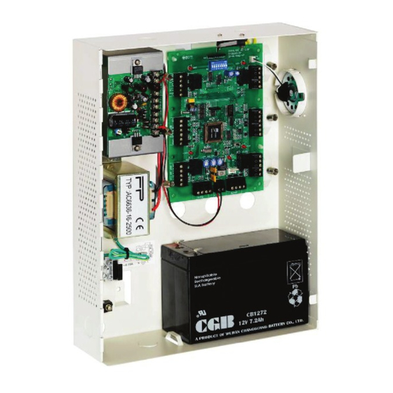
- Page 25 Hardware Installation Guide Power Supply The following diagram illustrates wiring between the PS-14 power supply and the AC-215. It is recommended to add a 12VDC lead acid backup battery to backup power if the main fails. If the main output is 12VDC wire it to the (PS-14), otherwise support your power supply according to output requirements.
- Page 26 AC-215 Single and Double Door Access Control Unit Hardware Installation Guide Reader Proximity and keypad readers are supplied with a limited cable. The color of the cable covering represents the cable’s function. When extending cable distance be careful with the color of the cable cover. The distance is limited by the Wiegand standard.
-
Page 27: A C C E S S O R I E S
AC-215 Single and Double Door Access Control Unit Hardware Installation Guide Proximity Readers AY-x09 Series PIN Readers AY-C09 / AY-D09 For indoor use Slim stylish design (Mullion) Includes LED indicator Audible buzzer indicator Built in tamper (w/ Rosslare controllers) ... -
Page 28: Ay-X11 Series Prox Readers
AC-215 Single and Double Door Access Control Unit Hardware Installation Guide AY-x11 Series Prox Readers AY-C11 / AY-D11 Reading distance: 8 to 10cm RF modulation: ASK at 125 kHz For indoor use Slim stylish design (USA gang box) ... -
Page 29: Ay-X19 Series Pin & Prox Readers
AC-215 Single and Double Door Access Control Unit Hardware Installation Guide AY-x19 Series Pin & Prox Readers AY-C19 / AY-D19 Reading distance: 8 to 10cm RF modulation: ASK at 125 kHz For indoor use Slim stylish design (USA gang box) ... - Page 30 3. Connect MD-N32's DB9 male jack to MD-14's DB9 female jack with cross serial cable. Connect the AC-215's RS-485 outlet to MD-14 4 wires cable. Make sure that J1 (on the AC-215) is set to RS485 Mode. If the jumper was not set properly, make the change, turn...
- Page 31 AC-215 Single and Double Door Access Control Unit Hardware Installation Guide MD-N32 Configuring in AxTrax AS-525 1. Add a new network in AxTrax AS-525 software. (For more details see AxTrax user Manuals) The network type should be selected as TCP/IP.
- Page 32 AC-215 Single and Double Door Access Control Unit Hardware Installation Guide 3. Click OK. 4. Select the suitable MAC address from the MD-N32 list (The MD-N32's MAC address should be labeled on the MD-N32's box). At the "Configuration" area, type the IP Address and Subnet which the network administrator supplied you.
- Page 33 AC-215 Single and Double Door Access Control Unit Hardware Installation Guide 5. Click OK to start verification process and wait for following message: 6. Click OK twice and verify that the configuration was accepted by the AxTrax AS-525 software.
- Page 34 AC-215 Single and Double Door Access Control Unit Hardware Installation Guide The MD-N32 and AxTrax AS-525 software are now configured ready for testing. (From this stage, you can continue working per the AxTrax AS-525 adding new panel procedure).
- Page 35 6. Connect MD-N33's DB9 female jack to MD-14's DB9 female jack. Connect the AC-215's RS-485 outlet to MD-14 4 wires cable. Make sure that J1 (on the AC-215) is set to RS485 Mode. If the jumper was not set properly, make the change, turn...
- Page 36 AC-215 Single and Double Door Access Control Unit Hardware Installation Guide MD-N33 configuration in AxTrax AS-525 1. Add a new network in AxTrax AS-525 software. (For more details see AxTrax user Manuals) The network type should be selected as Modem.
- Page 37 AC-215 Single and Double Door Access Control Unit Hardware Installation Guide 3. Click to change the "number of dial attempts" (if needed). 4. For most applications, the default dialing string of AS-525 is enough. The dialing string is displayed in the window.
- Page 38 AC-215 Single and Double Door Access Control Unit Hardware Installation Guide Remote modem – configuration and initialization 1. Click the Remote modem tab to configure the remote modem. 2. Settings section: For most applications, the default initialization string of AS-525 is enough.
- Page 39 AC-215 Single and Double Door Access Control Unit Hardware Installation Guide The MD-N33 and AxTrax AS-525 software are now configured ready for testing. (From this stage, you can continue working per the AxTrax AS-525 adding new panel procedure).
- Page 40 2. There is a manually option to dial or disconnect the modem. 3. In order to prevent access to AxTrax AS-525 data from non authorities users, the AC-215 contain a password that can be changed only when the modem is connect and there is a link with AC-215.
- Page 41 AC-215 Single and Double Door Access Control Unit Hardware Installation Guide Restoring factory default configuration If you forgot the existing password, there is an option to return AC-215 to factory default (with password: AxTrax). Caution: Returning to factory default will change also all the doors and readers configuration to Factory default and clears all the users' properties.
-
Page 42: P S S
AC-215 Single and Double Door Access Control Unit Hardware Installation Guide ACU uses the PS-14 power supply. Transformer AC transformer 120/220V AC / 16V AC 2.5A (40VA),class 2 (not included) PS-14 Power Supply 16V AC/2.5A Input voltage/current: From transformer 13.8V... -
Page 43: T E C H N I C A L S U P P O R T
Asia Pacific, Middle East, Africa Rosslare Security Products Headquarters 905-912 Wing Fat Industrial Bldg, 12 Wang Tai Road, Kowloon Bay Hong Kong Tel: +852 2795-5630 Fax: +852 2795-1508 E-mail: support.apac@rosslaresecurity.com United States and Canada 1600 Hart Court, Suite 103 Southlake, TX, USA 76092... - Page 44 www.rosslaresecurity.com...
Need help?
Do you have a question about the AC-215 and is the answer not in the manual?
Questions and answers