
Subscribe to Our Youtube Channel
Related Manuals for Rosslare O2S AY-G6270


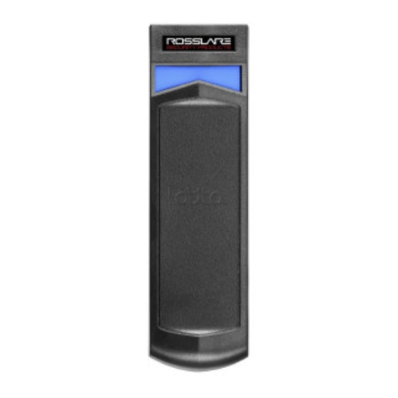
Summary of Contents for Rosslare O2S AY-G6270
- Page 1 AY-G/H6xx0 Family Open to Secure™ (O2S®) Readers Installation and User Manual Models: AY-G6270/G6280 AY-G6370/G6380 AY-H6270/H6280 AY-H6370/H6380 AY-H6270/H6280 AY-G6270/G6280 AY-G6370/G6380 AY-H6370/H6380...
- Page 2 ROSSLARE. ROSSLARE reserves the right to revise and change this document at any time, without being obliged to announce such revisions or changes beforehand or after the fact.
-
Page 3: Table Of Contents
Exiting Programming Mode ........... 17 Selecting Keypad Transmission Format ........17 Keypad Transmission Format Option Number ......18 7.5.1 Option 1: Single Key, Wiegand 6-Bit (Rosslare Format) ....19 7.5.2 Option 2: Single Key, Wiegand 6-Bit Nibble and Parities ....19 7.5.3 Option 3: Single Key, Wiegand 8-Bit Nibbles Complemented .. - Page 4 Table of Contents Changing the Facility Code ............ 23 Setting the Backlight Behavior ..........24 Return to Factory Default Settings .......... 25 7.10 Replacing a lost Programming Code ........25 OSDP Operation ............26 Wiegand Output Formats ......... 27 Rules for Wiegand 26-Bit (26A) ..........28 Rules for Wiegand 38-Bit (38A) ..........
- Page 5 List of Figures List of Figures Figure 1: Mounting..................11 AY-G/H6xx0 Installation and User Manual...
- Page 6 List of Tables List of Tables Table 1: Wiring ....................12 Table 2: Reader Programming Menu ............... 16 Table 3: Keypad Transmission Format .............. 18 Table 4: Bit Description Table ................27 AY-G/H6xx0 Installation and User Manual...
- Page 7 ROSSLARE exclusive warranty and liability is limited to the warranty and liability statement provided in an appendix at the end of this document. This manual describes the maximum configuration of the system with the ...
-
Page 8: Introduction
Box Content Before beginning, verify that all of the following is in the box. If anything is missing, please report the discrepancy to your nearest Rosslare office. One O2S reader Installation kit – Includes two wall plugs, two mounting screws, ... -
Page 9: Technical Specifications
Outdoor Usage Weather-resistant, meets IP65, epoxy-potted, suitable for indoor and outdoor use * Measured using Rosslare O2S ISO cards. Range also depends on electrical environment and proximity to metal. ** Standard configuration. Custom configurations are available. AY-G/H6xx0 Installation and User Manual... - Page 10 Technical Specifications Physical Characteristics Dimensions of Pigtail AY-G6xx0: 145.3 x 42.0 x 23.0 mm (5.7 x 1.7 x 0.9 in.) Models (H x W x D) AY-H6xx0: 120.0 x 80.0 x 23.0 mm (4.7 x 3.2 x 0.9 in.) Dimensions of Terminal AY-G6xx0: 145.3 x 42.0 x 31.0 mm Block and OSDP Models (5.7 x 1.7 x 1.2 in.)
-
Page 11: Mounting
Mounting Mounting To mount the units: 1. Determine an approximate location for the reader. 2. Peel off the back of the self-adhesive mounting label template and place it at the required mounting location. 3. Using the template as a guide, drill two holes (sizes indicated on the template) used for mounting the back plate onto the surface (Figure 1). -
Page 12: Wiring Instructions
Wiring Instructions Wiring Instructions The units are supplied with a 10-conductor 18” (46 cm) pigtail or with 10 terminal blocks. To connect a pigtail reader to the controller: 1. Prepare the reader cable by cutting its jacket back 3.2 cm (1¼”) and strip the insulation from the wires 1.3 cm (½"). - Page 13 Wiring Instructions • The individual wires from the reader are color coded according the Wiegand standard. • When using a separate power supply for the reader, this supply and that of the controller must have a common ground. • The reader’s cable shield wire should be preferably attached to an earth ground, or a signal ground connection at the panel, or power supply end of the cable.
-
Page 14: Reader Operation
Reader Operation Reader Operation Once the reader is wired to a power supply and to the controller, you should test the reader. To test the reader: 1. Power up the reader. The beeper sounds three times and the LED turns red, blue, and green, to indicate that the reader is working properly. -
Page 15: Proximity Operation
Proximity Operation Proximity Operation Supported Credential Technologies O2S readers support reading from the secure memory of the following credential technologies: AY-H6x80 and AY-G6x80 MIFARE DESFire EV1 (2K, 4K, 8K) MIFARE Classic EV1 (1K, 4K) AY-H6x70 and AY-G6x70 ... -
Page 16: Keypad Operation Instructions
Menu Description Default Selecting Keypad Transmission Format 1 – Single Key, Wiegand 6-Bit (Rosslare Format) 2 – Single Key, Wiegand 6-Bit with Nibble + Parity Bits 3 – Single Key, Wiegand 8-Bit, Nibbles Complemented 4 – 4 Keys Binary + Facility code, Wiegand 26-Bit 5 –... -
Page 17: Entering Programming Mode
Keypad Operation Instructions Entering Programming Mode To reach the Programming Menu System, the unit must first be placed into Programming mode. To enter Programming mode: 1. Press # four times. The yellow LED blinks. 2. Enter your Programming code. If the Programming code is valid, and the unit is in Programming mode and the yellow LED is lit. -
Page 18: Keypad Transmission Format Option Number
Transmission Format you wish to select. Table 3: Keypad Transmission Format Keypad Transmission Format Option Number Single Key, Wiegand 6-Bit (Rosslare Format) Single Key, Wiegand 6-Bit with Nibble + Parity Bits Single Key, Wiegand 8-Bit, Nibbles Complemented 4 Keys Binary + Facility code, Wiegand 26-Bit... -
Page 19: Option 1: Single Key, Wiegand 6-Bit (Rosslare Format)
Keypad Operation Instructions 7.5.1 Option 1: Single Key, Wiegand 6-Bit (Rosslare Format) Each key press immediately sends 4 bits with 2 parity bits added – even parity for the first 3 bits and odd parity for the last 3 bits. -
Page 20: Option 4: 4 Keys Binary + Facility Code, Wiegand 26-Bit
Keypad Operation Instructions 7.5.4 Option 4: 4 Keys Binary + Facility Code, Wiegand 26-Bit This option buffers 4 keys and outputs keypad data with a 3-digit Facility code like a standard 26-bit card output. The Facility code is set in Programming Menu 4 and can be in the range 000 to 255. -
Page 21: Option 6: 6 Keys Bcd And Parity Bits, Wiegand 26-Bit
Keypad Operation Instructions When entering a keypad PIN code that is less than 5 digits in length, # must be pressed to signify the end of PIN code entry. For keypad PIN codes that are 5 digits in length, on the fifth key press of the 5-digit PIN code, the data is sent across the Wiegand Data lines as binary data in the same format as a 26-bit card. -
Page 22: Option 8: 1 To 8 Keys Bcd, Clock & Data
Keypad Operation Instructions Where: EP = Even parity for first 12 bits OP = Odd parity for last 12 bits A = The first key entered D = Fourth key entered B = Second key entered E = Fifth key entered C = Third key entered F = Sixth key entered 7.5.7... -
Page 23: Option 9: Single Key, Wiegand 4-Bit
Keypad Operation Instructions 7.5.8 Option 9: Single Key, Wiegand 4-Bit With this option, each key press immediately sends 4 bits of data, with no parity bits added. 0 = 0000 6 = 0110 1 = 0001 7 = 0111 2 = 0010 8 = 1000 3 = 0011 9 = 1001... -
Page 24: Setting The Backlight Behavior
Keypad Operation Instructions The system returns to Standby mode. You hear three beeps and the green LED blinks • The Facility code can be in the range of 000 to 255. • The default Facility code is 0. Setting the Backlight Behavior To set the backlight behavior: 1. -
Page 25: Return To Factory Default Settings
Keypad Operation Instructions Return to Factory Default Settings You must be very careful before using this command! This erases the entire memory and returns all codes to their factory default setting. To return to factory default settings: 1. Enter Programming mode. 2. -
Page 26: Osdp Operation
OSDP Operation OSDP Operation Rosslare O2S readers that support OSDP operation are compatible with most OSDP commands. The reader address is set using DIP switches on the back of the reader. The DIP switch settings are as follows: DIP Switch 1 This switch is used to select the reader output (Wiegand or OSDP): ... -
Page 27: Wiegand Output Formats
Wiegand Output Formats Wiegand Output Formats The AY-G/H6xx0 can read all Rosslare O2S cards/tags and outputs card ID data in Wiegand format according to the number of bits stored in the secured memory area on the card. The readers support any O2S card from 26-bit to 128-bit. -
Page 28: Rules For Wiegand 26-Bit (26A)
Wiegand Output Formats Rules for Wiegand 26-Bit (26A) Field ID Data Facility Code Parity Bits # of Bits Range 65,535 Wiegand 26-Bit Reader Output Bit 1 – "E" Even parity of bits 2 to 13, designated by "X" Bit 2 to 9 – "F" 8-Bit Facility Code Bit 26 –... - Page 29 Wiegand Output Formats Example: FC=59, ID=21,003 AY-G/H6xx0 Installation and User Manual...
-
Page 30: Rules For Wiegand 38-Bit (38A)
# of Bits Range 65,535 1,023 Bit 38 – "E" Even Wiegand 38-Bit parity of bits 20 to 37, (Rosslare designated by Parity Proprietary) Reader Mask "X" Output Bit 2 – "O" Odd parity of bits 3 to 20, designated by Parity Mask "X"... - Page 31 Wiegand Output Formats Example: ISSUE No=0, FC=905, Site Code=103, ID=9,029 AY-G/H6xx0 Installation and User Manual...
-
Page 32: Declaration Of Conformity
Declaration of Conformity Declaration of Conformity This device complies with Part 15 of the FCC Rules. Operation is subject to the following two conditions: This device may not cause harmful interference. This device must accept any interference received, including ... -
Page 33: Limited Warranty
The full ROSSLARE Limited Warranty Statement is available in the Quick Links section on the ROSSLARE website at www.rosslaresecurity.com. Rosslare considers any use of this product as agreement to the Warranty Terms even if you do not review them. AY-G/H6xx0 Installation and User Manual... - Page 34 Tel: +86-755-8610 6842 Fax: +86-755-8610 6101 Rosslare Security Products, Inc. support.cn@rosslaresecurity.com Southlake, TX, USA India Toll Free: +1-866-632-1101 Local: +1-817-305-0006 Rosslare Electronics India Pvt Ltd. Fax: +1-817-305-0069 Tel/Fax: +91-20-40147830 support.na@rosslaresecurity.com Mobile: +91-9975768824 Europe sales.in@rosslaresecurity.com Rosslare Israel Ltd. Rosh HaAyin, Israel...
Need help?
Do you have a question about the O2S AY-G6270 and is the answer not in the manual?
Questions and answers