Table of Contents
Advertisement
Quick Links
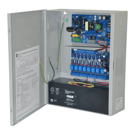
eFlowNAD8V Series
Access Power Controllers with
Power Supply/Chargers
Models Include:
eFlow4NA8DV
- 4A @ 12VDC or 24VDC
- Eight (8) PTC Outputs
eFlow6NA8DV
- 6A @ 12VDC or 24VDC
- Eight (8) PTC Outputs
For a red enclosure add an "R" suffix to the part # e.g. eFlow4NA8DVR
Installation Guide
Rev. eFlowNA8DV062117
Installing Company: _______________ Service Rep. Name: __________________________________
Address: _____________________________________________ Phone #: __________________
eFlow102NA8DV
- 10A @ 12VDC
- Eight (8) PTC Outputs
eFlow104NA8DV
- 10A @ 24VDC
- Eight (8) PTC Outputs
More than just power.
TM
Advertisement
Table of Contents

Subscribe to Our Youtube Channel
Related Manuals for Altronix eFlowNAD8V Series


Summary of Contents for Altronix eFlowNAD8V Series
- Page 1 Series Access Power Controllers with Power Supply/Chargers Models Include: eFlow4NA8DV eFlow102NA8DV - 4A @ 12VDC or 24VDC - 10A @ 12VDC - Eight (8) PTC Outputs - Eight (8) PTC Outputs eFlow6NA8DV eFlow104NA8DV - 6A @ 12VDC or 24VDC...
-
Page 2: Table Of Contents
Table of Contents: Overview ..............pg. 3 eFlowNA8DV Series Configuration Reference Chart . -
Page 3: Overview
Overview: Altronix eFlowNA8DV Series distribute and switch power to access control systems and accessories. They convert a 220VAC (working range 198VAC - 256VAC), 50/60Hz input into eight (8) independently controlled 12VDC or 24VDC PTC protected auto-resettable outputs. These power outputs can be converted to dry form “C” contacts. -
Page 4: Eflowv Power Supply/Charger
eFlowV Power Supply/Charger: • Input: 220VAC (working range 198VAC - 256VAC), 50/60Hz. • For output voltage and supply current refer to eFlowNA8DV Series Configuration Chart, pg. 3. • Auxiliary power-limited output rated @ 1A (unswitched). • Overvoltage protection. • Built-in charger for sealed lead acid or gel type batteries. •... - Page 5 14. Installation of tamper switch (Fig. 3a, pg. 9): Mount UL Listed tamper switch (Altronix Model TS112 or equivalent) at the top of the enclosure. Slide the tamper switch bracket onto the edge of the enclosure approximately 2” from the right side (Fig. 3a, pg. 9).
-
Page 6: Maintenance
15. Multiple power supply inputs (Fig. 2, pg. 8): When using an additional Listed external power supply, jumpers J1 and J2 located on corresponding ACM8CB board must be cut (Fig. 2c, 2d, pg. 8 and Fig. 5, pg. 11). Connect external Listed power-limited access control power supply to the terminals marked [–... -
Page 7: Power Supply Board Terminal Identification
Power Supply Board Terminal Identification: Terminal Legend Function/Description Connect 220VAC 50/60Hz to these terminals: L to hot, N to neutral. L, N Do not use terminal marked [G] + DC – Factory connected to ACM8CB board. Trigger EOL Fire Alarm Interface trigger input from a short or FACP. Trigger inputs can be normally Supervised open, normally closed from an FACP output circuit (power-limited input) (Fig. -
Page 8: Power Supply Board Output Voltage Settings
Power Supply Board Output Voltage Settings: Fig. 1 Fig. 1a Switch Detail Switch On - 12V Switch Off - 24V Access Power Controller Typical Application Diagram (ACM8CB): Fig. 2 Fig. 2a Intact = Dry Input Normally Open (N.O.) Cut = Wet Input Door Releasing FACP FACP... - Page 9 Fig. 3 - eFlowNA8DV Series Configuration Fig. 3a Enclosure Edge of Enclosure Tamper Switch (included) To Access Control Panel or UL Listed Reporting Device Tamper Switch Ground Lug Battery & AC Supervision Circuit (power-limited) AC DC 1 min enable NC C NO NC C NO TRIGGER NO GND 2 hr...
-
Page 10: Nec Power-Limited Wiring Requirements For Eflowna8Dv Models
NEC Power-Limited Wiring Requirements for eFlowNA8DV Models: Power-limited and non power-limited circuit wiring must remain separated in the cabinet. All power-limited circuit wiring must remain at least 0.25” away from any non power-limited circuit wiring. Furthermore, all power-limited circuit wiring and non power-limited circuit wiring must enter and exit the cabinet through different conduits. One such example of this is shown below. -
Page 11: Optional Hook-Up Using Two (2) Isolated Power Supply Inputs
Hook-Up Diagrams: Fig. 5 Optional hook-up using two (2) isolated power supply inputs (Only applicable on eFlow4NA8D: CUT JUMPERS J1 AND J2 ISOLATED POWER INPUT 12 OR 24 VAC OR VDC (ACM8 POWER) ISOLATED POWER INPUT 12 OR 24 VAC OR VDC (LOCK POWER) Fig. -
Page 12: Normally Open Facp Latching Trigger Input With Reset
Hook-Up Diagrams: Fig. 8 Normally Open FACP Latching trigger input with reset (This output has not been evaluated by UL): FACP N.O. TRIGGER INPUT N.C. RESET SWITCH JUMPER Fig. 9 Normally Closed: Non-Latching FACP trigger input: FACP N.C. DRY TRIGGER INPUT JUMPER Fig. -
Page 13: Optional Linq2 - Network Communication Module
- UL Listed in the U.S. and Canada. - Local or remote control of up to (2) two Altronix eFlow power output(s) via LAN and/or WAN. - Monitor real time diagnostics: DC output voltage, output current, AC & battery status/service, input trigger state change, output state change and unit temperature. - Page 14 WARNING: To reduce the risk of fire or electric shock, do not expose the unit to rain or moisture. This installation should be made by qualified service personnel and should conform to the National Electrical Code and all local codes. The lightning flash with arrowhead symbol within an equilateral triangle is intended to alert the user to the presence of an insulated DANGEROUS VOLTAGE within the product’s enclosure that may be of sufficient magnitude to constitute an electric shock.
- Page 15 Notes eFlowNA8DV Series Installation Guide - 15 -...
-
Page 16: Enclosure Dimensions
1.5” 4.615” (117.2mm) 4.615” (117.2mm) (38.1mm) (38.1mm) Altronix is not responsible for any typographical errors. –––––––––––––––––––––––––––––––––––––––––––––––––––––––––––––––––––––––––––––––––––––––––––––––––––––––––––––––– 140 58th Street, Brooklyn, New York 11220 USA | phone: 718-567-8181 | fax: 718-567-9056 website: www.altronix.com | e-mail: info@altronix.com | Lifetime Warranty IIeFlowNA8DV Series...
Need help?
Do you have a question about the eFlowNAD8V Series and is the answer not in the manual?
Questions and answers