Table of Contents
Advertisement
Quick Links
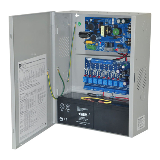
Access Power Controllers
with Power Supplies
Installation Guide
Models include:
eFlow4NA8DV
- 4A @ 12VDC or 24VDC
- Eight (8) PTC Outputs
eFlow102NA8DV
- 10A @ 12VDC
- Eight (8) PTC Outputs
For a red enclosure add an "R" suffix to the part #, e.g. eFlow4NA8DVR
Rev. eFlowNA8DV062117
Installing Company: ________________ Service Rep. Name: ______________________________________
Address: ___________________________________________________ Phone #: _____________________
eFlow6NA8DV
- 6A @ 12VDC or 24VDC
- Eight (8) PTC Outputs
eFlow104NA8DV
- 10A @ 24VDC
- Eight (8) PTC Outputs
More than just power.
TM
Advertisement
Table of Contents

Related Manuals for Altronix eFlowNA8DV Series


Summary of Contents for Altronix eFlowNA8DV Series
- Page 1 Access Power Controllers with Power Supplies Installation Guide Models include: eFlow4NA8DV eFlow6NA8DV - 4A @ 12VDC or 24VDC - 6A @ 12VDC or 24VDC - Eight (8) PTC Outputs - Eight (8) PTC Outputs eFlow102NA8DV eFlow104NA8DV - 10A @ 12VDC - 10A @ 24VDC - Eight (8) PTC Outputs - Eight (8) PTC Outputs...
-
Page 2: Table Of Contents
Series Configuration Reference Chart ....... . . pg. 3... -
Page 3: Overview
Overview: Altronix eFlowNA8DV Series distribute and switch power to access control systems and accessories. They convert a 220VAC (working range 198VAC - 256VAC), 50/60Hz input into eight (8) independently controlled 12VDC or 24VDC PTC protected auto-resettable outputs. These power outputs can be converted to dry form “C”... -
Page 4: Eflowv Power Supply/Charger
Power Supply/Charger: • Input: 220VAC (working range 198VAC - 256VAC), 50/60Hz. • For output voltage and supply current refer to eFlowNA8DV Series Configuration Chart, pg. 3. • Auxiliary power-limited output rated @ 1A (unswitched). • Overvoltage protection. • Built-in charger for sealed lead acid or gel type batteries. - Page 5 14. Installation of tamper switch (Fig. 3a, pg. 9): Mount UL Listed tamper switch (Altronix Model TS112 or equivalent) at the top of the enclosure. Slide the tamper switch bracket onto the edge of the enclosure approximately 2” from the right side (Fig. 3a, pg. 9).
-
Page 6: Maintenance
Output Voltage Test: Under normal load conditions the DC output voltage should be checked for proper voltage level (refer to eFlowNA8DV Series Configuration Chart, pg. 3). Battery Test: Under normal load conditions check that the battery is fully charged, check specified voltage at the battery terminals and at the board terminals marked [+ BAT –] to ensure that there is no break in the battery... -
Page 7: Power Supply Board Terminal Identification
Fire Alarm Interface trigger input from FACP. Trigger inputs can be normally open, T, + INPUT – normally closed from an FACP signaling circuit output (Figs. 5-10, pg. 11-12). FACP INTERFACE Form “C” relay contact rated @ 1A 28VDC for alarm reporting. NC, C, NO eFlowNA8DV Series - 7 -... -
Page 8: Power Supply Board Stand-By Battery Specifications
Fig. 2d Fig. 2c removed. MAG. Electromagnetic LOCK Door Holders Intact = One P/S Input Intact = DC Input Cut = Dual P/S Input Cut = AC Input J2 J1 NC C NO COM OUTPUT 8 - 8 - eFlowNA8DV Series... - Page 9 Keep power-limited wiring separate from non power-limited. Use minimum 0.25" spacing. 12AH Rechargeable batteries are the largest batteries that can fit in this enclosure. A UL listed external battery enclosure must be used if using the 40AH or 65AH batteries. eFlowNA8DV Series - 9 -...
-
Page 10: Nec Power-Limited Wiring Requirements For Eflowna8Dv Models
(non power- limited) ACM8CB outputs (power- limited) Battery Connections (non power- limited) Fig. 4a Incorrect Wire Correct Wire Handling Handling External Jacketed Shield Wire Insulation Pull back Solid Copper external jacketed Conductors shield approx. 1/2”. - 10 - eFlowNA8DV Series... -
Page 11: Facp Hook-Up Diagrams
Fig. 6 Polarity reversal input from FACP signaling circuit output (polarity is referenced in alarm condition): JUMPER FACP OUTPUT EOL FROM FACP OUTPUT CIRCUIT Fig. 7 Normally Open - Non-Latching FACP trigger input: N.O. TRIGGER INPUT eFlowNA8DV Series - 11 -... -
Page 12: Normally Open Facp Latching Trigger Input With Reset
N.C. RESET SWITCH JUMPER Fig. 9 Normally Closed - Non-Latching FACP trigger input: N.C. DRY TRIGGER INPUT JUMPER Fig. 10 Normally Closed - Latching FACP trigger input with reset: N.C. RESET SWITCH N.C. TRIGGER JUMPER INPUT - 12 - eFlowNA8DV Series... -
Page 13: Optional Linq2 - Network Communication Module
- UL Listed in the U.S. and Canada. - Local or remote control of up to (2) two Altronix eFlow power output(s) via LAN and/or WAN. - Monitor real time diagnostics: DC output voltage, output current, AC & battery status/service, input trigger state change, output state change and unit temperature. - Page 14 Notes - 14 - eFlowNA8DV Series...
- Page 15 Notes eFlowNA8DV Series - 15 -...
-
Page 16: Enclosure Dimensions
(117.22mm) (38.1mm) Altronix is not responsible for any typographical errors. 140 58th Street, Brooklyn, New York 11220 USA | phone: 718-567-8181 | fax: 718-567-9056 website: www.altronix.com | e-mail: info@altronix.com | Lifetime Warranty | Made in U.S.A. MEMBER IIeFlowNA8DV Series F07R...
Need help?
Do you have a question about the eFlowNA8DV Series and is the answer not in the manual?
Questions and answers