Table of Contents
Advertisement
Quick Links
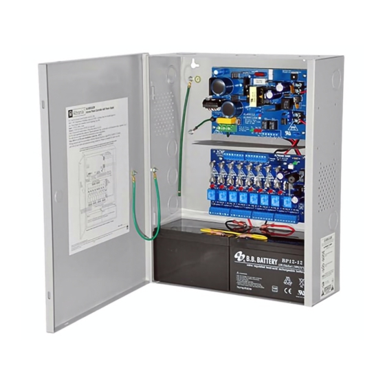
eFlowNA8 Series
Access Power Controllers with
Power Supply/Chargers
Models Include:
eFlow4NA8
- 4A @ 12VDC or 24VDC
- Eight (8) Fused Outputs
eFlow6NA8
- 6A @ 12VDC or 24VDC
- Eight (8) Fused Outputs
ULC-S319 - Electronic Access Control Systems will be invalidated through the use of any add-on, expansion,
memory or other module manufactured by the manufacturer or other manufacturers.
For a red enclosure add an "R" suffix to the part # e.g. eFlow4NA8R
Installation Guide
Rev. eACM050919
Installing Company: _______________ Service Rep. Name: __________________________________
Address: _____________________________________________ Phone #: __________________
eFlow102NA8
- 10A @ 12VDC
- Eight (8) Fused Outputs
eFlow104NA8
- 10A @ 24VDC
- Eight (8) Fused Outputs
Altronix Corp.
140 58th St. Brooklyn, NY
More than just power.
TM
Advertisement
Table of Contents


Need help?
Do you have a question about the eFlowNA8 Series and is the answer not in the manual?
Questions and answers