Table of Contents
Advertisement
Quick Links
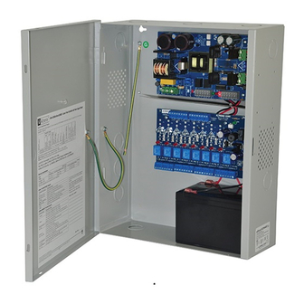
eFlowNA8D Series
Access Power Controllers with
Power Supply/Chargers
Models Include:
eFlow4NA8D
- 4A @ 12VDC or 24VDC
- Eight (8) PTC Outputs
eFlow6NA8D
- 6A @ 12VDC or 24VDC
- Eight (8) PTC Outputs
For a red enclosure add an "R" suffix to the part # e.g. eFlow6NA8DR
Installation Guide
Rev. eACMCB052319
Installing Company: _______________ Service Rep. Name: __________________________________
Address: _____________________________________________ Phone #: __________________
Altronix Corp.
140 58th St. Brooklyn, NY
eFlow102NA8D
- 10A @ 12VDC
- Eight (8) PTC Outputs
eFlow104NA8D
- 10A @ 24VDC
- Eight (8) PTC Outputs
More than just power.
TM
Advertisement
Table of Contents

Related Manuals for Altronix eFlowNA8D Series


Summary of Contents for Altronix eFlowNA8D Series
- Page 1 Series Access Power Controllers with Power Supply/Chargers Models Include: eFlow4NA8D eFlow102NA8D - 4A @ 12VDC or 24VDC - 10A @ 12VDC - Eight (8) PTC Outputs - Eight (8) PTC Outputs eFlow104NA8D eFlow6NA8D - 10A @ 24VDC - 6A @ 12VDC or 24VDC...
- Page 2 Outputs will operate in both Fail-Safe and/or Fail-Secure modes. The FACP Interface enables Emergency Egress, Alarm Monitoring, or may be used to trigger other auxiliary devices. The fire alarm disconnect feature is individually selectable for any or all of the eight (8) outputs. eFlowNA8D Series Configuration Reference Chart: Nominal DC Output Voltage Options...
-
Page 3: Power Supply Board Stand-By Battery Specifications
• ACM8CB board main fuses are rated @ 10A. Output PTCs are rated @ 2.5A. eFlow Power Supply/Charger: • Input: 120VAC, 60Hz. • For output voltage and supply current refer to eFlowNA8D Series Configuration Chart, pg. 2. • Auxiliary Power-Limited output rated @ 1A (unswitched). • Overvoltage protection. -
Page 4: Installation Instructions
REX PIRs, etc. to terminals marked [IN] and [GND]. (b) Open Collector Sink inputs: Connect the access control panel open collector sink positive (+) to terminals marked [IN] and the negative (–) to terminals marked [GND]. - 4 - eFlowNA8D Series Installation Guide... - Page 5 14. Installation of tamper switch (Fig. 3a, pg. 8): Mount UL Listed tamper switch (Altronix model TS112 or equivalent) at the top of the enclosure. Slide the tamper switch bracket onto the edge of the enclosure approximately 2” from the right side (Fig. 3a, pg. 8).
-
Page 6: Maintenance
Output Voltage Test: Under normal load conditions the DC output voltage should be checked for proper voltage level (refer to eFlowNA8D series Configuration Chart, pg. 2). Battery Test: Under normal load conditions check that the battery is fully charged, check specified voltage at the battery terminals and at the board terminals marked [–... -
Page 7: Terminal Identification
T, + INPUT – normally closed from an FACP signaling circuit output (Figs. 6-10, pg. 10). FACP INTERFACE Form “C” relay contact rated @ 1A 28VDC for alarm reporting (not evaluated by UL). NC, C, NO eFlowNA8D Series Installation Guide - 7 -... -
Page 8: Power Supply Board Output Voltage Settings
Fig. 2c MAG. LOCK removed. Electromagnetic Door Holders Intact = One P/S Input Intact = DC Input Cut = Dual P/S Input Cut = AC Input J2 J1 NC C NO COM OUTPUT 8 - 8 - eFlowNA8D Series Installation Guide... - Page 9 Fig. 3 - eFlowNA8D Series Configuration Fig. 3a Enclosure Edge of Enclosure Tamper Switch (included) To Access Control Panel or UL Listed Reporting Device Tamper Switch OFF - 24V ON - 12V eFlow4NB - power-limited eFlow6NB, eFlow102NB, eFlow104NB - non power-limited...
- Page 10 (non power- limited) ACM8CB outputs (power- Battery limited) Connections (non power-limited) Fig. 4a Incorrect Wire Correct Wire Handling Handling External Jacketed Shield Wire Insulation Pull back Solid Copper external jacketed Conductors shield approx. 1/2”. - 10 - eFlowNA8D Series Installation Guide...
-
Page 11: Hookup Diagrams
Fig. 6 Polarity reversal input from FACP signaling circuit output (polarity is referenced in alarm condition): JUMPER FACP FACP OUTPUT EOL FROM FACP OUTPUT CIRCUIT Fig. 7 Normally Open: Non-Latching FACP trigger input: FACP N.O. TRIGGER INPUT eFlowNA8D Series Installation Guide - 11 -... - Page 12 Fig. 9 Normally Closed: Non-Latching FACP trigger input: FACP N.C. DRY TRIGGER INPUT JUMPER Fig. 10 Normally Closed: Latching FACP trigger input with reset (This output has not been evaluated by UL): FACP N.C. RESET SWITCH N.C. TRIGGER JUMPER INPUT - 12 - eFlowNA8D Series Installation Guide...
- Page 13 Notes: eFlowNA8D Series Installation Guide - 13 -...
- Page 14 Notes: - 14 - eFlowNA8D Series Installation Guide...
- Page 15 1.5” 4.615” (117.2mm) 4.615” (117.2mm) (38.1mm) (38.1mm) Altronix is not responsible for any typographical errors. –––––––––––––––––––––––––––––––––––––––––––––––––––––––––––––––––––––––––––––––––––––––––––––––––––––––––––––––– 140 58th Street, Brooklyn, New York 11220 USA | phone: 718-567-8181 | fax: 718-567-9056 website: www.altronix.com | e-mail: info@altronix.com | Lifetime Warranty IIeFlowNA8D Series...
- Page 16 - UL Listed in the U.S. and Canada. - Local or remote control of up to (2) two Altronix eFlow power output(s) via LAN and/or WAN. - Monitor real time diagnostics: DC output voltage, output current, AC & battery status/service, input trigger state change, output state change and unit temperature.
Need help?
Do you have a question about the eFlowNA8D Series and is the answer not in the manual?
Questions and answers