Table of Contents
Advertisement
Quick Links
Advertisement
Table of Contents
Troubleshooting

Subscribe to Our Youtube Channel
Related Manuals for Furuno FAR21x7 & BB FAR28x7 Operator's Manual BB FAR28x7


Summary of Contents for Furuno FAR21x7 & BB FAR28x7 Operator's Manual BB FAR28x7
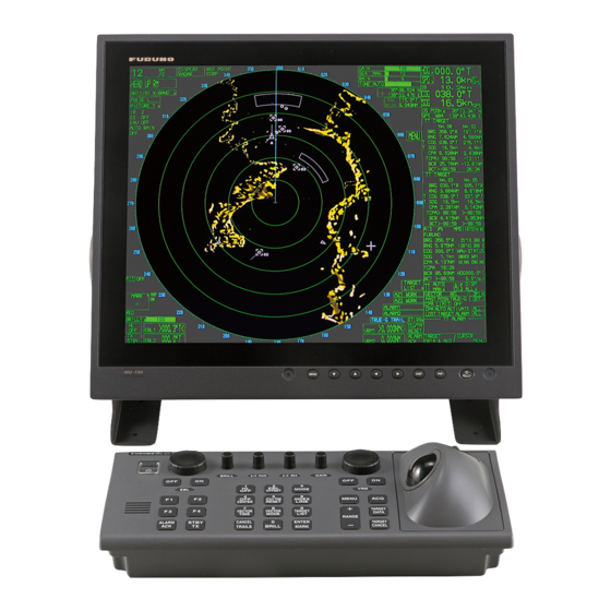
- Page 1 Back MARINE RADAR/ARPA FAR-28x7 Series FAR-21x7(-BB) Series www.furuno.co.jp...
- Page 2 The paper used in this manual is elemental chlorine free. ・FURUNO Authorized Distributor/Dealer 9-52 Ashihara-cho, Nishinomiya, 662-8580, JAPAN Telephone : +81-(0)798-65-2111 : +81-(0)798-65-4200 A : JAN 2004 Printed in Japan All rights reserved. G2 : OCT . 31, 2007 Pub. No. OME-35190-G2...
- Page 3 • Store this manual in a convenient place for future reference. • FURUNO will assume no responsibility for the damage caused by improper use or modification of the equipment (including software) by an unauthorized agent or a third party.
- Page 4 Note: If the antenna unit is installed at a close distance in front of the wheel house, your administration may require halt of transmission within a certain sector of antenna revolution. This is possible. Ask your FURUNO representative or dealer to provide this feature.
- Page 5 SAFETY INSTRUCTIONS WARNING WARNING ELECTRICAL SHOCK HAZARD Use the proper fuse. Do not open the equipment. Use of a wrong fuse can result in damage Only qualified personnel to the equipment or cause fire. should work inside the equipment. Keep heater away from equipment. Heat can alter equipment shape and melt Turn off the radar power the power cord, which can cause fire or...
- Page 6 WARNING LABEL Warning labels are attached to the equipment. Do not remove any label. If a label is missing or damaged, contact a FURUNO agent or dealer about replacement. DISPLAY UNIT, PROCESSOR UNIT WARNING Name: Warning Label (1) To avoid electrical shock, do not remove cover.
-
Page 7: Table Of Contents
TABLE OF CONTENTS TABLE OF CONTENTS FOREWORD ......................xi PROGRAM NUMBER ..................xiv SYSTEM CONFIGURATION................xv SPECIFICATIONS................... SP-1 1. RADAR OPERATION..................1-1 1.1 Turning on the Power....................1-1 1.2 Transmitter ON ......................1-1 1.3 Control Unit........................ 1-3 1.4 Main Menu......................... 1-5 1.5 Operation Using the On-Screen Boxes .............. - Page 8 SAFETY INSTRUCTIONS 1.21 Measuring the Bearing .....................1-33 1.21.1 Measuring the bearing ...................1-33 1.21.2 Choosing true or relative bearing ..............1-35 1.22 Collision Assessment by Offset EBL.................1-36 1.22.1 How to assess risk of collision by the offset EBL..........1-36 1.22.2 Choosing point of reference for origin point of offset EBL.......1-37 1.23 Measuring Range and Bearing Between Two Targets ..........1-38 1.24 Setting a Target Alarm ....................1-39 1.24.1 How to set a target alarm zone ..............1-39...
- Page 9 TABLE OF CONTENTS 1.36 Noise Rejector ......................1-70 1.37 Suppressing Second-trace Echoes................1-71 1.38 Adjusting Brilliance of Screen Data................1-72 1.39 Watch Alarm ......................1-73 1.40 Setting Up Nav Data ....................1-74 1.41 Text Window Setup ....................1-76 1.42 Customizing Operation .................... 1-78 1.43 Alarms ........................
- Page 10 SAFETY INSTRUCTIONS 3.6.1 Setting manual acquisition conditions ............. 3-7 3.6.2 Manually acquiring a target ................3-7 3.7 ARP Symbols and ARP Symbol Attributes..............3-9 3.7.1 ARP symbols ....................3-9 3.7.2 Choosing ARP symbol (B, C and W types).............3-10 3.7.3 ARP symbol brilliance ..................3-10 3.7.4 ARP symbol color and size ................3-11 3.7.5 Auto target track (A, B, C and W types) ............3-12 3.8 Displaying Target Data .....................3-13...
- Page 11 TABLE OF CONTENTS 4.7.2 Detailed target data ..................4-9 4.8 AIS Symbol Attributes ....................4-10 4.8.1 AIS symbol brilliance ..................4-10 4.8.2 AIS symbol size and color ................4-11 4.9 Past Position Display ....................4-12 4.9.1 Displaying and erasing past position points, choosing past position plot interval....................
- Page 12 SAFETY INSTRUCTIONS 5.12.3 Erasing waypoints..................5-24 5.12.4 Waypoint list ....................5-25 5.12.5 Displaying waypoint name and number............5-26 5.13 Nav Lines .........................5-27 5.13.1 Entering new nav line..................5-27 5.13.2 Editing nav lines.....................5-28 5.13.3 Nav line list ....................5-29 5.13.4 Erasing nav lines ...................5-30 5.13.5 Setting up nav lines..................5-31 5.13.6 Displaying nav line, waypoint mark ..............5-33 5.14 Recording Data ......................5-35 5.14.1 Initializing memory (RAM) cards ..............5-35...
-
Page 13: Foreword
A Word to the Owner of the FAR-28x7/FAR-21x7(-BB) Congratulations on your choice of the FURUNO FAR-28x7/FAR-21x7(-BB) Series Radar. We are confident you will see why FURUNO has become synonymous with quality and reliability. For over 50 years FURUNO Electric Company has enjoyed an enviable reputation for innovative and dependable marine electronics equipment. - Page 14 2002 and also complies with the R&TTE Directive 1999/5/EC. In accordance with Article 6-3 of the above-mentioned R&TTE directive, FURUNO intends to put this radar on the market of the following countries in EU as well other markets: Austria, Belgium, Cyprus, Denmark,...
- Page 15 FOREWORD Radar Type and Function Availability This radar series is available in five specification types to meet the requirements of Authorities, and function availability depends on specification type. The table below shows those functions which have limited availability. This manual provides descriptions for all functions in this radar series, and we have endeavored to denote in the text those functions which have limited availability.
-
Page 16: Program Number
PROGRAM NUMBER PC Board Program No. Version No. MAIN 035-9204 02.** (Merchant) / 50.** (Fishing) 035-9202 01.** KEY(REMOTE) 035-9203 01.** ARPA 035-9212 01.** ** Minor modification... -
Page 17: System Configuration
SYSTEM CONFIGURATION See page xvi for detailed information about antenna units and radiators. With FURUNO-supplied monitor FAR-2137S/2167DS/2837S/2837SW FAR-2117/2127/2157/2817/2827/2827W ANTENNA UNIT ANTENNA UNIT (Performance Monitor PM-51* built in) (Performance Monitor PM-31* built in) * Neither FAR-2157 nor FAR-2167DS carry a performance monitor. - Page 18 SYSTEM CONFIGURATION Antenna unit FAR-2117, RSB-096 (24 rpm) RSB-097 (42 rpm) FAR-2117-BB, FAR-2127, FAR-2127-BB, FAR-2827 FAR-2137S, RSB-098/099 (21/26 rpm, 200 VAC, 3ø, 50 Hz; 220 VAC, 3ø, 60 Hz; 380 FAR-2137S-BB VAC, 3ø, 50 Hz, 440 VAC, 3ø, 60 Hz) RSB-100/101/102 (45 rpm, 220 VAC, 3ø, 50/60 Hz(HSC);...
- Page 19 SYSTEM CONFIGURATION Blackbox type FAR-2137S-BB/FR-2167DS-BB FAR-2117-BB/2127-BB/FAR-2157-BB ANTENNA UNIT ANTENNA UNIT (Performance Monitor PM-51 built in (Performance Monitor PM-31 built in FAR-2117-BB, FAR-2127-BB) FAR-2137S-BB) * Neither FAR-2157-BB nor FAR-2167DS-BB carry a performance monitor. MONITOR CONTROL UNIT RCU-014 POWER SUPPLY UNIT (Keyboard) PSU-006 (For FAR-2157-BB/2167DS-BB) RCU-015...
- Page 20 SYSTEM CONFIGURATION Console type RCN-001/RCN-002 FAR-2137S/2837S/2837SW FAR-2117/2127/2817/2827/2827W ANTENNA UNIT ANTENNA UNIT (Performance Monitor PM-51 built in) (Performance Monitor PM-31 built in) Waveguide Waveguide or (For FAR-2827W) Coax cable (For FAR-2837SW) TRANSCEIVER UNIT TRANSCEIVER UNIT RTR-081 RTR-082 For FAR-2827W For FAR-2837SW CONSOLE Alarm RCN-001/002...
- Page 21 SYSTEM CONFIGURATION Console type RCN-003/RCN-004 FAR-2137S/2837S/2837SW FAR-2117/2127/2817/2827/2827W ANTENNA UNIT ANTENNA UNIT (Performance Monitor PM-51 built in) (Performance Monitor PM-31 built in) Waveguide Waveguide or (For FAR-2827W) Coax cable (For FAR-2837SW) TRANSCEIVER UNIT TRANSCEIVER UNIT RTR-081 RTR-082 For FAR-2827W For FAR-2837SW CONSOLE Alarm RCN-003/004...
- Page 22 SYSTEM CONFIGURATION (This page intentionally left blank.)
-
Page 23: Specifications
FURUNO FAR-21x7(-BB)/28x7 SERIES SPECIFICATIONS OF MARINE RADAR/ARPA FAR-21x7(-BB)/28x7 SERIES 1. ANTENNA RADIATORS 1. Type Slotted waveguide array 2. Beam width and sidelobe attenuation X-band S-band Radiator type XN12AF XN20AF XN24AF SN30AF SN36AF XN4A XN5A Length 8 ft 10 ft 4 ft 6.5 ft... -
Page 24: Display Unit
11. Parallel index line Choice of 2, 4 or 6 lines 12. AIS IMO SN Circ.217, IEC/PAS 60936-5 13. Chart cards FURUNO and NAVIONICS 4. INTERFACE 1. IEC 61162-1 Ed. 2 RSD, TTM, AIS related data, etc. 2. Compass Built-in interface (option) for sync signal (20-135 V, 50-400 Hz), or... -
Page 25: Power Supply
FURUNO FAR-21x7(-BB)/28x7 SERIES PM-51 (S-band) 1. Frequency range 3020 to 3080 MHz 2. Input power Min. -5 dBm, Max. +15 dBm 3. Power output (2 pulse max output) -15 dBm 4. Power output (2 pulse min output) -35 dBm 5. Steps levels (1... -
Page 26: Optional Equipment
FURUNO FAR-21x7(-BB)/28x7 SERIES 8. OPTIONAL EQUIPMENT SWITCHING HUB HUB-100 1. Access Format CSMA/CD 2. Switching Format Store and Forward 3. Transmission Speed Half-duplex: 10Mbps/100Mbps Full-duplex: 20Mbps/200Mbps 4. Necessary Cabling 10BASE-T: Category 3 or higher STP cable 100 BASE-TX: Category 5 or higher STP cable 5. -
Page 27: Radar Operation
RADAR OPERATION Turning on the Power The [POWER] switch ( ) is located at the left corner of the control unit. Open the POWER switch cover and press the switch to turn on the radar system. To turn off the radar, press the switch again. The screen shows the bearing scale and digital timer approximately 30 seconds after power-on. - Page 28 1. RADAR OPERATION The radar is initially set to previously used range and pulse length. Other settings such as brilliance levels, VRMs, EBLs and menu option selections are also set to previous settings. The [STBY/TX] key (or TX STBY box) toggles the radar between STBY and TRANSMIT status.
-
Page 29: Control Unit
1. RADAR OPERATION Control Unit Two types of control units are available: Control Unit RCU-014 (full keyboard) and Control Unit RCU-105 (palm control). EBL rotary control VRM rotary control Wheel Left button Right button BRILL A/C RAIN A/C SEA GAIN MODE OFFSET CU/TM... - Page 30 1. RADAR OPERATION Control description Control Description Control Unit RCU-014 (full keyboard) POWER Turns the system on and off. EBL and VRM rotary controls Adjust EBL and VRM, respectively. EBL ON, EBL OFF Turns the EBLs on and off, respectively. F1-F4 Execute menu short cut assigned.
-
Page 31: Main Menu
1. RADAR OPERATION Main Menu You may access the MAIN menu from the full keyboard or by using the trackball. In later sections only the procedure for menu operation by trackball is given. Main menu operation by keyboard 1. Press the [MENU] key. The MAIN menu appears in the text area at the right side of the screen. - Page 32 1. RADAR OPERATION Main menu operation by trackball 1. Roll the trackball to choose the MENU box at the right side of the screen. The guidance box at the bottom right corner (see the illustration at the bottom of the next page for location) now reads “DISP MAIN MENU.” MENU Menu box 2.
-
Page 33: Operation Using The On-Screen Boxes
1. RADAR OPERATION Operation Using the On-Screen Boxes All radar functions can be accessed by using the trackball alone. This is done by choosing the appropriate on-screen box with the trackball and operating the trackball module to choose item and option. (See paragraph 1.9 for location of all on-screen boxes.) On-screen boxes come in two varieties: Function selection and function selection w/pop-up menu. - Page 34 1. RADAR OPERATION Trackball marker location and guidance box indication The trackball marker is either a cursor (+) or an arrow ( ) depending on whether it is within or outside the display area, respectively. Further, the indication in the guidance box changes according to trackball marker location.
- Page 35 1. RADAR OPERATION 3. The pop-up menu attached to the MARK box is the MARK menu. To open the menu, push the right button. The menu opens in the text area at the right side of the screen. [MARK MENU] 1 ORIGIN MARK STAB GND/SEA 2 MARK KIND...
-
Page 36: Cursor Menu
1. RADAR OPERATION Cursor Menu Functions which require the use of the cursor, such as EBL offset and zoom, may be activated directly [CURSOR MENU] from the guidance box or from the CURSOR menu, ↓ either method with the cursor inside the effective TARGET DATA &... -
Page 37: Monitor Brilliance
1. RADAR OPERATION 6. The guidance box shows “XX / EXIT.” (XX = function chosen). Roll the trackball to place the cursor where desired. 7. Push the left button to execute the function selected at step 5. 8. To quit the function selected, push the right button when the guidance box shows “XX / EXIT.”... -
Page 38: Choosing The Display Mode
1. RADAR OPERATION Choosing the Display Mode This radar has two display modes: Radar and Radar + Plotter. Choose a display mode as below. Note that a display mode cannot be chosen when the menu is open. 1. Roll the trackball to place the arrow in the DISPLAY MODE box at the top of the screen. -
Page 39: On-Screen Boxes And Markers
1. RADAR OPERATION On-Screen Boxes and Markers Reference Point Box Trial Maneuver (Elapsed time shown when trial maneuver is active.) PICTURE Box, Main Picture Settings SET and DRIFT Boxes PULSELENGTH Box CURSOR DATA Box ANTENNA Box PRESENTATION MODE Box GAIN Setting RANGE Box A/C SEA Setting Note: Speed, Set and... - Page 40 1. RADAR OPERATION Heading is TRUE 242.2°T (variation-corrected gyro or magnetic heading) 9.9kt BT 0.1kt Speed data is LOG, MAN, etc., showing sensor and types. 30.2°T 10.2.2kt CSE when water tracking mode is selected. OS POSN 34°40.00N STW when water tracking Electronic Position-fixing DGPS 135°24.00E...
-
Page 41: Tuning The Receiver
1. RADAR OPERATION 1.10 Tuning the Receiver 1.10.1 Choosing the tuning method The tuning method can be selected with the TUNE box at the top of the screen. 1. Roll the trackball to choose the TUNE box (TUNE AUTO or TUNE MAN) at the top of the screen. -
Page 42: Automatic Tuning
However, if the GYRO readout looks wrong or the gyro alarm sounds, follow the procedure below. Note that the FURUNO SC-60/120 does not require alignment on the radar. 1. Roll the trackball to place the arrow in the HDG box at the top right corner of the screen. -
Page 43: Presentation Modes
1. RADAR OPERATION 1.12 Presentation Modes This radar has the following presentation modes: Relative Motion (RM) Head-up: Unstabilized Head-up TB: Head-up with compass-stabilized bearing scale (True Bearing) where the bearing scale rotates with the compass reading. Course-up: Compass-stabilized relative to ship’s orientation at the time of selecting course-up. -
Page 44: Description Of Presentation Modes
1. RADAR OPERATION 1.12.2 Description of presentation modes Head-up mode The head-up mode is a display in which the line connecting own ship and the top of the display indicates own ship’s heading. The target pips are painted at their measured distances and in their directions relative to own ship’s heading. - Page 45 1. RADAR OPERATION Head-up TB (True Bearing) mode Radar echoes are shown in the same way as in the head-up mode. The difference from normal head-up presentation lies in the orientation of the bearing scale. The bearing scale is heading sensor stabilized. That is, it rotates in accordance with the heading sensor signal, enabling you to know own ship’s heading at a glance.
- Page 46 1. RADAR OPERATION True motion mode Own ship and other moving objects move in accordance with their true courses and speed. In ground stabilized TM, all fixed targets, such as landmasses, appear as stationary echoes. In the sea stabilized TM without set and drift inputs, the landmass can move on the screen.
-
Page 47: Entering Own Ship's Speed
The ARP and azimuth stabilized presentation modes require own ship speed input and compass signal. The speed can be entered from a log (STW) or GPS (SOG) or manually on the menu. Note that FURUNO GPS Navigator GP-90 provides COG and SOG. -
Page 48: Manual Speed Input
1. RADAR OPERATION 1.13.2 Manual speed input If the speed log is not working, enter speed manually as below. In this case the speed data type is shown as MANUAL and is speed thru water (STW). Note that, for the IMO specification radar, manual speed input is not available when the AIS feature is active. -
Page 49: Choosing The Pulselength
1. RADAR OPERATION 1.15 Choosing the Pulselength The pulselength in use is displayed at the upper-left position of the screen using the indications shown in the table below. Label and pulselength Indication Pulselength (μs) S1 (Short pulse 1) 0.07 S2 (Short pulse 2) 0.15 M1 (Medium pulse 1) M2 (Medium pulse 2) -
Page 50: Changing Pulselength
1. RADAR OPERATION 3. Roll the wheel to choose 8 [PULSE] and then push the wheel. [PULSE MENU] [PULSE MENU] 1 BACK 1 BACK 2 0.5NM 2 0.75NM S1/S2 S/M1 3 0.75NM 3 1.5NM S1/S2/M1 S/M1 4 1.5NM 4 3NM S1/S2/M1 M1/M2 5 3NM... -
Page 51: Adjusting The Sensitivity
1. RADAR OPERATION 1.16 Adjusting the Sensitivity The gain control adjusts the sensitivity of the receiver. The proper setting is such that the background noise is just visible on the screen. If you set up for too little sensitivity, weak echoes may be missed. On the other hand excessive sensitivity yields too much background noise;... -
Page 52: Suppressing Sea Clutter
1. RADAR OPERATION 1.17 Suppressing Sea Clutter Echoes from waves cover the central part of the display with random signals known as sea clutter. The higher the waves, and the higher the antenna above the water, the further the clutter will extend. When sea clutter masks the picture, suppress it by the A/C SEA control, either manually or automatically. -
Page 53: Manual Adjustment Of A/C Sea
1. RADAR OPERATION By trackball 1. Choose SEA AUTO following the procedure in paragraph 1.17.1. 2. Roll the trackball to place the arrow in the A/C SEA level indicator at the top of the display. 3. While observing the A/C SEA level indicator, roll the wheel downward to increase the A/C SEA or upward to decrease it. -
Page 54: Suppressing Rain Clutter
1. RADAR OPERATION 1.18 Suppressing Rain Clutter Use the AUTO RAIN and A/C RAIN to suppress rain clutter. AUTO RAIN suppresses rain clutter in the picture and A/C RAIN suppresses clutter picked up by the antenna. 1.18.1 Turning AUTO RAIN on or off 1. -
Page 55: Adjusting A/C Rain
1. RADAR OPERATION 1.18.2 Adjusting A/C RAIN The vertical beam width of the antenna is designed to see surface targets even when the ship is rolling. However, by this design the unit will also detect rain clutter (rain, snow, or hail) in the same manner as normal targets. The A/C RAIN control adjusts the receiver sensitivity as the A/C SEA control does but rather in a longer time period (longer range). -
Page 56: Interference Rejector
1. RADAR OPERATION 1.19 Interference Rejector Mutual radar interference may occur in the vicinity of another shipborne radar operating in the same frequency band. It is seen on the screen as a number of bright spikes either in irregular patterns or in the form of usually curved spoke-like dotted lines extending from the center to the edge of the picture. -
Page 57: Measuring The Range
1. RADAR OPERATION 1.20 Measuring the Range The range to a target may be measured three ways: with the fixed range rings, with the cursor, or with the VRM. Use the fixed range rings to obtain a rough estimate of the range to a target. They are the concentric solid circles about own ship, or the sweep origin. -
Page 58: Measuring Range By The Variable Range Marker (Vrm)
1. RADAR OPERATION 1.20.2 Measuring range by the variable range marker (VRM) There are two VRMs, No. 1 and No. 2, which appear as dashed rings so that you can discriminate them from the fixed range rings. The two VRMs can be distinguished from each other by different lengths of dashes. -
Page 59: Choosing Vrm Unit Of Measurement (B, C And W Types)
1. RADAR OPERATION 1.20.3 Choosing VRM unit of measurement (B, C and W types) 1. Roll the trackball to choose the MENU box at the right side of the screen. The guidance box at the bottom right corner now reads “DISP MAIN MENU.” 2. - Page 60 1. RADAR OPERATION By trackball 1. Roll the trackball to place the arrow in the EBL1 or EBL2 box, whichever EBL you want to use. EBL1 EBL2 EBL boxes 2. The guidance box reads “EBL ON/.” Push the left button to turn on the EBL. The guidance box now reads “EBL SET L=DELETE /.”...
-
Page 61: Choosing True Or Relative Bearing
1. RADAR OPERATION 1.21.2 Choosing true or relative bearing The EBL readout is affixed by “R.” (relative) if it is relative to own ship's heading, ”T.” (true) if it is referenced to the north. You may choose relative or true in the head-up modes;... -
Page 62: Collision Assessment By Offset Ebl
1. RADAR OPERATION 1.22 Collision Assessment by Offset EBL The origin of the EBL can be placed anywhere with the trackball to enable measurement of range and bearing between any targets. This function is also useful for assessment of the potential risk of collision. It is possible to read CPA (Closest Point of Approach) by using a VRM as shown below (Figure (a)). -
Page 63: Choosing Point Of Reference For Origin Point Of Offset Ebl
1. RADAR OPERATION No. 1 No. 1 ° >138.2 T< ° >150.3 T< >3.85NM< >3.85NM< VRM1 EBL1 EBL1 VRM1 Collision assessment by offset EBL 1.22.2 Choosing point of reference for origin point of offset EBL The origin point of the offset EBL can be ground stabilized (geographically fixed) or referenced to own ship’s heading (relative). -
Page 64: Measuring Range And Bearing Between Two Targets
1. RADAR OPERATION 1.23 Measuring Range and Bearing Between Two Targets By keyboard 1. Press the [EBL OFFSET] key. Operate the trackball to place the origin of the No. 1 EBL, for example, on a target of interest (target 1 in the illustrated example). -
Page 65: Setting A Target Alarm
1. RADAR OPERATION 1.24 Setting a Target Alarm The target alarm serves to alert the navigator to targets (ships, landmasses, etc.) entering a set area, with audible and visual alarms. CAUTION The guard alarm zone has a fixed width of 0.5 nm in the radial direction •... -
Page 66: Acknowledging The Target Alarm
1. RADAR OPERATION Note 1: If you wish to create a target alarm zone having a 360-degree coverage around own ship, set point “B” in almost the same direction as point “A.” Note 2: Two target alarm zones may be set. Note however that the 2 target alarm zone is available only when the 1 target alarm zone is active. -
Page 67: Target Alarm Attributes
1. RADAR OPERATION 1.24.4 Target alarm attributes You may choose the echo strength level which triggers the alarm, the condition which generates the target alarm and the volume of the audible alarm as follows: 1. Roll the trackball to choose the MENU box at the right side of the screen and then push the left button. -
Page 68: Off-Centering The Display
1. RADAR OPERATION 1.25 Off-Centering the Display Own ship position, or sweep origin, can be displaced to expand the view field without switching to a larger range scale. The sweep origin can be off-centered to the cursor position, but not more than 75% of the range in use; if the cursor is set beyond 75% of the range scale, the sweep origin will be off-centered to the point of 75% of the limit. -
Page 69: Echo Stretch
1. RADAR OPERATION 1.26 Echo Stretch The echo stretch feature enlarges targets in the range and bearing directions to make them easier to see, and it is available on any range. There are three types of echo stretch, 1, 2 and 3, and the higher the number the greater the amount of stretching. -
Page 70: Echo Averaging
1. RADAR OPERATION 1.27 Echo Averaging The echo averaging feature effectively suppresses sea clutter. Echoes received from stable targets such as ships appear on the screen at almost the same position every rotation of the antenna. On the other hand, unstable echoes such as sea clutter appear at random positions. -
Page 71: Target Trails
1. RADAR OPERATION 1.28 Target Trails The trails of the radar echoes of targets may be displayed in the form of synthetic afterglow. Target trails are chosen either relative or true and may be sea or ground stabilized. True motion trails require a compass signal and own ship speed input. -
Page 72: Trail Time
1. RADAR OPERATION 1.28.2 Trail time Trail time, the trail plotting interval, may be chosen as follows: 1. Roll the trackball to place the arrow on the TRAIL MODE box at the bottom right corner of the screen. * TRAIL ** * = TRUE or REL ** = Trail time setting TRAIL MODE box... -
Page 73: Saving, Copying Target Trails
1. RADAR OPERATION 1.28.4 Saving, copying target trails By turning on the functions TRAIL RESTART and TRAIL COPY, you may continue painting target trails whenever the range scale is changed. The amount of range change determines how the radar paints trails. See the table below for details. -
Page 74: Trail Level
1. RADAR OPERATION The relationship between trail restart and trail copy depends on their status, as shown in the table below. Trail restart Trail copy Trail status Range changed while trail is ON: Trails continue on targets within previous range. Range changed while trail is ON: Trails within the previous range are erased and then trails are restarted. -
Page 75: Longer Trails (B, C And W Types)
1. RADAR OPERATION 1.28.7 Longer trails (B, C and W types) In addition to the trail times mentioned in paragraph 1.28.2, you may also extend trails 12 or 24 hours. 1. Roll the trackball to place the arrow on the TRAIL MODE box at the bottom right corner of the screen. -
Page 76: Parallel Index Lines
1. RADAR OPERATION 1.29 Parallel Index Lines Parallel index lines are useful for keeping a constant distance between own ship and a coastline or a partner ship when navigating. Two index lines are available and any two may be displayed. You may control the orientation and line interval. Index lines Parallel index lines... -
Page 77: Adjusting Index Line Orientation, Index Line Interval
1. RADAR OPERATION 1.29.2 Adjusting index line orientation, index line interval 1. Display the index line for which you want to adjust its orientation, referring to paragraph 1.29.1. 2. Roll the trackball to place the arrow in IL 1 the index line orientation setting Index line orientation 032.0°T Index line interval... -
Page 78: Choosing Maximum Number Of Index Lines To Display
1. RADAR OPERATION 1.29.4 Choosing maximum number of index lines to display The maximum number of index lines to display may be chosen from 2, 3 or 6 lines as below. The actual number of lines visible may be less depending on line interval. -
Page 79: Origin Mark
1. RADAR OPERATION 1.30 Origin Mark You can mark any prominent target or a point of particular interest using the origin mark feature. Twenty origin marks may be entered: 10 standard origin marks (with number) and one each of the 10 symbol origin marks. The marks may be geographically fixed (ground stabilized) or sea stabilized. - Page 80 1. RADAR OPERATION 7. With the cursor choosing the MARK box, roll the wheel to choose mark number desired (“ORIGIN MARK(No.)” chosen at step 4) or origin mark symbol (“ORIGIN MARK(SYM)” chosen at step 4) and then push the left button.
-
Page 81: Origin Mark Stabilization
1. RADAR OPERATION 1.30.2 Origin mark stabilization Origin marks may be geographically fixed (ground stabilized) or moving (sea stabilized). 1. Roll the trackball to choose the MARK box. 2. Push the right button to open the MARK menu. [MARK MENU] 1 ORIGIN MARK STAB GND/SEA 2 MARK KIND... -
Page 82: Zoom
1. RADAR OPERATION 1.31 Zoom The zoom function enlarges an area of interest as large as twice the normal viewing size, in the text window. To use the zoom display, it must be turned on in the DATA BOX menu. For further details, see paragraph 1.41. Zoom is not available when the ARP target data setting is “LARGE”... -
Page 83: Markers
1. RADAR OPERATION 1.32 Markers 1.32.1 Heading marker and heading line The heading marker and the heading line indicate the ship's heading in all presentation modes. The heading line is a line from the own ship position to the outer edge of the radar display area and appears at zero degrees on the bearing scale in head-up mode;... -
Page 84: Barge Marker
1. RADAR OPERATION 1. Roll the trackball to choose the MENU box at the right side of the display and then push the left button to display the MAIN menu. 2. Roll the wheel to choose MARK and then push the wheel or the left button to show the MARK menu. -
Page 85: Automatic Picture Setup According To Navigation Purpose
1. RADAR OPERATION 1.33 Automatic Picture Setup According to Navigation Purpose Every time your navigating environment or task changes, you must adjust the radar, which can be a nuisance in a busy situation. Instead of changing radar settings case by case, it is possible to assign the function keys to provide optimum settings for often encountered situations. - Page 86 1. RADAR OPERATION Picture setup options and default settings for X-band (12 kW/25 kW) and S-band (30 kW) radars 1 INT 2 ECHO 3 ECHO 4 NOISE 5 AUTO 6 AUTO 7 VIDEO REJECT STRETCH AVERAGE RAIN CONTRAST PICTURE 1 PICTURE 2 PICTURE 3 PICTURE 4...
-
Page 87: Choosing A Picture Setup Option
1. RADAR OPERATION 1.33.1 Choosing a picture setup option You may choose a picture setup options as follows: 1. Roll the trackball to choose the PICTURE box at the left side of the screen. NEAR BUOY* * Other possible indications: NEAR, FAR, FAR BUOY, ROUGH SEA, SHIP, HARBOR, COAST,... -
Page 88: User-Programmable Picture Setups
1. RADAR OPERATION 4. Roll the wheel to choose 0 DEFAULT. 5. Push the wheel or the left button three times to restore default settings for the picture setup selected. (If you are using the keyboard, press the [ENTER MARK] key three times.) 6. - Page 89 1. RADAR OPERATION B: Curve between A and C. C: Mid-level in the curve is high, so this setting is suitable for detecting distant targets. PICTURE level 5 db * Default 7 db 9 db 11 db VIDEO SIGNAL level Video contrast settings 7.
-
Page 90: Programming Function Keys
1. RADAR OPERATION 1.34 Programming Function Keys Less-often used functions are provided in the menu. To avoid opening the menus to set up the radar for a particular situation, function keys F1-F4 may be assigned any of the functions shown in the CUSTOMIZE•TEST sub menu. 1.34.1 Activating a function key To activate the function assigned to a function key, press the key to instantly set... - Page 91 1. RADAR OPERATION 4. Roll the wheel to choose appropriate category, ECHO, STD KEY, ARP•AIS, OPERATION or PICTURE and then push the wheel or the left button. Refer to the menus below to choose appropriate category. [ECHO] [STD KEY] 1 BACK 1 BACK PICTURE/ ALARM ACK/...
- Page 92 1. RADAR OPERATION 5. Roll the wheel to choose “2” and then push the wheel or the left button. 6. Roll the wheel to choose function desired and then push the wheel or left button. 7. Push the right button twice to close the menu. Description of function key programs Item Description...
- Page 93 1. RADAR OPERATION Description of function key programs (con’t from previous page) Item Description [ARP•AIS] DISP ARP Activates/deactivates ARP. DISP AIS Activates/deactivates AIS. TARGET DATA & ACQ ARP: Acquires ARP target; shows data for ARP target selected. AIS: Activates sleeping AIS target; shows data for AIS target selected.
- Page 94 1. RADAR OPERATION Description of function key programs (con’t from previous page) Item Description [PICTURE] Actuates settings of user-programmed setup. PICTURE1 – PICTURE4 NEAR Optimum setting for short range detection using a range scale of 3 nm or less on calm seas Optimum setting for long range detection using a range scale of 6 nm or larger NEAR BUOY...
-
Page 95: Ship's Position
1. RADAR OPERATION 1.35 Ship’s Position Choose the source of ship’s position data as follows: 1. Roll the trackball to choose the OS POSN box at the top right corner of the screen. OS POSN OS POSN box 2. Push the right button to show the OS POSN menu. [OS POSN MENU] 1 NAV AID GPS1/GPS2/... -
Page 96: Noise Rejector
1. RADAR OPERATION 1.36 Noise Rejector White noise may show itself on the screen as random “speckles” spread over the entire radar image. You can remove this noise as follows: 1. Roll the trackball to choose the PICTURE box at the left side of the screen. 2. -
Page 97: Suppressing Second-Trace Echoes
1. RADAR OPERATION 1.37 Suppressing Second-trace Echoes In certain situations, echoes from very distance targets may appear as false echoes (second-trace echoes) on the screen. This occurs when the return echo is received one transmission cycle later, or after a next radar pulse has been transmitted. -
Page 98: Adjusting Brilliance Of Screen Data
1. RADAR OPERATION 1.38 Adjusting Brilliance of Screen Data You can adjust relative brilliance levels of various markers and alphanumeric readouts displayed on the screen. 1. Roll the trackball to choose the BRILL box at the bottom left corner of the screen and then push the right button to show the BRILL menu. -
Page 99: Watch Alarm
1. RADAR OPERATION 1.39 Watch Alarm The watch alarm sounds the audible alarm at the chosen time interval to help you keep regular watch of the radar picture for safety or other purposes. The WATCH box appears at the lower-left corner of the screen with a watch alarm timer counts down from value set (for example, “12:00”). -
Page 100: Setting Up Nav Data
1. RADAR OPERATION 1.40 Setting Up Nav Data Wind, depth, ocean current, water temperature, date and time and waypoint data may be set up as follows: 1. Roll the trackball to choose the MENU box at the right side of the screen and then push the left button. - Page 101 1. RADAR OPERATION Nav data menu description Item Description 2 DEPTH Chooses unit of depth measurement, or turn depth indication off. 3 DEPTH GRAPH SCALE Chooses depth scale range. The echogram shows the last 30 minutes of sounding along the ship’s track. 4 DEPTH MARK Chooses the depth at which to show the depth mark.
-
Page 102: Text Window Setup
1. RADAR OPERATION 1.41 Text Window Setup The text window, displayed at the right 1/4 of the screen, mainly shows nav data, zoomed target, and ARP target data. You can set up this window as follows: 1. Roll the trackball to choose the MENU box at the right side of the screen and then push the left button. - Page 103 1. RADAR OPERATION 10. Roll the wheel to choose zoom display format and then push the wheel or the left button. REL: Zoom display moves in relative motion STAB: Zoom display is ground stabilized (geographically fixed) ACQ: Zoom ARP targets 11.
-
Page 104: Customizing Operation
1. RADAR OPERATION 1.42 Customizing Operation Several operation items may be customized to suit your needs. 1. Roll the trackball to choose the MENU box at the right side of the screen and then push the left button. 2. Roll the wheel to choose 9 [CUSTOMIZE•TEST] and then push the wheel or the left button to open the CUSTOMIZE•TEST menu. - Page 105 1. RADAR OPERATION Operation menu items Item No. Description Options 2 WHEEL DRIVE Choose how to cycle data when NORMAL: Cycles numeral using the wheel. data in numeric order and indication data in clockwise order. REVERSE: Reverse of NORMAL. 3 KEY BEEP Key beeps when key sequence OFF: No key beep has been correctly executed.
-
Page 106: Alarms
1. RADAR OPERATION 1.43 Alarms When error is detected, the appropriate alarm indication appears (in red) and the audible alarm sounds. Silence the audible alarm with the [ALARM ACK] key or choose the ALARM ACK box and then push the left button. The error indication remains on the display until the reason for the alarm is removed. - Page 107 1. RADAR OPERATION Alarm description (con’t from previous page) Warning Audible Visual alarm To quit alarm status alarm EPFS Continuous EPFS in red (EPFS: electronic To silence the beep and failure beep position-fixing system) in the erase the message, press warning and indication cell.
-
Page 108: Outputting Alarm Signal
1. RADAR OPERATION 1.43.2 Outputting alarm signal Four ports are provided from which to output alarm signals to external equipment. Choose the port and alarm signals to output as follows: 1. Roll the trackball to choose the MENU box and then push the left button. 2. -
Page 109: Choosing The Antenna, Displaying Antenna Information
1. RADAR OPERATION 4. Roll the wheel to choose an alarm to output and then push the wheel or the left button. The alarm chosen is underlined. 5. Repeat step 5 to choose other alarms to output. 6. Push the right button three times to close the menu. 1.44 Choosing the Antenna, Displaying Antenna Information... -
Page 110: Displaying Antenna Information
1. RADAR OPERATION 1.44.2 Displaying antenna information The antenna information display shows data (radar band, model and position) on the radar antennas currently powered. If an antenna is not powered, its data area is blank. 1. Roll the trackball to place the arrow in the ANTENNA box at the left side of the screen. -
Page 111: Cursor Data
1. RADAR OPERATION 1.45 Cursor Data Cursor data can be shown in range and bearing from own ship, latitude and longitude position or cursor’s X-Y coordinates. 1. Roll the trackball to choose the CURSOR DATA box at the right side of the display. -
Page 112: Performance Monitor
1. RADAR OPERATION 1.46 Performance Monitor A performance monitor is required for a radar installed on vessels of 300 GT and upward engaged in international voyages. Two units are available: X-band radar: PM-31 (9410 ± 45 MHz) S-band radar: PM-51 (3050 ± 30 MHz). The performance monitor is incorporated in the antenna unit. - Page 113 1. RADAR OPERATION The range scale is automatically set to 24 nm. The radar screen will show one or two arcs. If the radar transmitter and receiver are in good working conditions in as much as the original state when the monitor was turned up, the innermost arcs should appear between 13.5 to 18.5 nm.
-
Page 114: Wiper
1. RADAR OPERATION 1.47 Wiper The wiper feature automatically suppresses the brilliance of weak signals (noise, sea clutter, rain clutter, etc.) and unwanted signals such as radar interference to clear the picture of unwanted echoes. Its effect depends on the wiper setting used and whether each averaging is turned on or off, as described below. -
Page 115: Own Ship Symbol
1. RADAR OPERATION 1.48 Own Ship Symbol Own ship symbol ( ) may be inscribed on the screen as below. You may enter ten such symbols. Each own ship symbols is shown with a number. 1. Roll the trackball to choose the MARK box at the left side of the screen. The guidance box now reads “MARK SELECT / MARK MENU.”... -
Page 116: Color And Brilliance Sets
1. RADAR OPERATION 1.49 Color and Brilliance Sets This radar provides four sets of color and brilliance sets to match any ambient lighting condition. The default colors are as shown in the table below. The default brilliance setting for any item is “50%”. BRILL1 BRILL2 BRILL3... -
Page 117: Reference Point For Cpa/Tcpa
1. RADAR OPERATION 5. Roll the wheel to choose 2 BKGD COLOR and then push the wheel or the left button. 6. Roll the wheel to choose background color and surrounding color combination desired and then push the wheel or the left button. 7. -
Page 118: Switching Hub Hub-100 (Option)
1. RADAR OPERATION 1.51 Switching Hub HUB-100 (option) The HUB-100 provides switching for a card interface unit and multiple processor units (max. 7), using an Ethernet interface (100BASE-TX/10BASE-T). LEDs display link/activity, mode (full-duplex or half-duplex) and collision statuses. No operation is required of the user. Simply turn on the HUB-100’s AC power source to power it. -
Page 119: 1.52 Dual Radar Display
1. RADAR OPERATION 1.52 Dual Radar Display The image from both X-band and S-band radars may be shown together on one radar display. This allows you to take advantage of the best characteristics each type of radar has to offer. Two display formats are available, mixed and combine, and you may select desired format from the menu. - Page 120 1. RADAR OPERATION Note 2: In the dual radar display, a guard zone set on the main radar is also accommodated on the external radar. When the position of the antennas for the main and external radars is different and the No. 2 guard zone is set on a close-in range, the on-screen guard zone may be shifted slightly from both the main radar antenna reference and external radar antenna reference.
- Page 121 1. RADAR OPERATION 7. Push the right button four times to close the menu. Note 1: The dual radar function becomes inoperative when the external radar is turned off, set to stand-by, or set as sub display. When this happens, the buzzer sounds and the message "EXT-STBY" (power off, stand-by only) appears.
-
Page 122: Specifying Sector Width And Length
1. RADAR OPERATION 1.52.2 Specifying Sector Width and Length When 2 DUAL RADA R in the DUAL RADAR menu is set for "COMBINE", specify the width and length o f the sector from the external radar to display on own radar. 1. - Page 123 1. RADAR OPERATION In the example below, START is 130° and ANGLE is 100°. Width of sector START ANGLE (Example: 130°) (Example: 100°) 9. Select 5 COMBINE RANGE and push the left button. 10. Use the scrollwheel to set START and LENGTH, referring to the example below. Spin the scrollwheel to set and push it to confirm.
-
Page 124: Choosing External Radar (Image Source)
1. RADAR OPERATION 1.52.3 Choosing External Radar (image source) Select the external radar to use in the dual radar display. 1. Right-click the MENU box. 2. Select 9 [CUSTOMIZE, TEST] and push the left button. 3. Select 7 [OPERATION] and push the left button. 4. -
Page 125: Radar Observation
RADAR OBSERVATION General 2.1.1 Minimum and maximum ranges Minimum range The minimum range is defined by the shortest distance at which, using a scale of 1.5 or 0.75 nm, a target having an echoing area of 10 m is still shown separate from the point representing the antenna position. - Page 126 This is determined by pulselength only. Practically, a 0.08 microsecond pulse offers the discrimination better than 35 m as do so with all FURUNO radars. Test targets for determining the range and bearing resolution are radar reflectors...
-
Page 127: False Echoes
2. RADAR OBSERVATION False Echoes Occasionally echo signals appear on the screen at positions where there is no target or disappear even if there are targets. They are, however, recognized if you understand the reason why they are displayed. Typical false echoes are shown below. - Page 128 2. RADAR OBSERVATION Virtual image A relatively large target close to your ship may be represented at two positions on the screen. One of them is the true echo directly reflected by the target and the other is a false echo which is caused by the mirror effect of a large object on or close to your ship as shown in the figure below.
-
Page 129: Sart (Search And Rescue Transponder)
2. RADAR OBSERVATION SART (Search and Rescue Transponder) 2.3.1 SART description A Search and Rescue Transponder (SART) may be triggered by any X-Band (3 cm) radar within a range of approximately 8 nm. Each radar pulse received causes it to transmit a response which is swept repetitively across the complete radar frequency band. -
Page 130: Showing Sart Marks On The Radar Display
2. RADAR OBSERVATION 2.3.2 Showing SART marks on the radar display This radar is equipped with a feature which optimally sets up the radar for SART detection. This feature automatically detunes the radar receiver out of its best tuning condition. This erases or weakens all normal radar echoes, but the SART marks are not erased because the SART response signal scans over all frequencies in the 9 GHz band. -
Page 131: General Remarks On Receiving Sart
2. RADAR OBSERVATION 2.3.3 General remarks on receiving SART SART range errors When responses from only the 12 low frequency sweeps are visible (when the SART is at a range greater than about 1 nm), the position at which the first dot is displayed may be as much as 0.64 nm beyond the true position of the SART. -
Page 132: Racon
2. RADAR OBSERVATION RACON A RACON is a radar beacon which emits radar receivable signals in the radar frequency spectrum (X- or S-band). There are several signal formats; in general, the RACON signal appears on the radar screen as a rectangular echo originating at a point just beyond the position of the radar beacon. -
Page 133: Arp Operation
ARP OPERATION Usage Precautions • This function is designed to meet the IMO requirements of both ARPA and ATA, and the desired function is selected during the installation of the equipment. For sake of brevity, this manual uses “ARP” when referring to ARPA or ATA. -
Page 134: Controls For Arp
3. ARP OPERATION Controls for ARP Keyboard The ARP uses the keys shown below. A/C RAIN A/C SEA BRILL GAIN MODE OFFSET CU/TM INDEX MENU CENTER RESET LINE TARGET VECTOR VECTOR TARGET DATA TIME MODE LIST RANGE ENTER TARGET ALARM STBY CANCEL CANCEL... -
Page 135: Activating, Deactivating Arp
3. ARP OPERATION Activating, Deactivating ARP To activate or deactivate the ARP: 1. Roll the trackball to place the arrow in the ARP ACQ MODE box at the right side of the display. (Note that “ATA” replaces “ARPA” when the ATA feature is used.) ARPA AUTO... - Page 136 3. ARP OPERATION 4. Push the left button to enter the reference mark. (The mark may also be entered by pressing the [ENTER MARK] key on the full keyboard.) The reference target mark (see below) appears at the cursor position and the own ship position data label changes from “LOG,”...
-
Page 137: Automatic Acquisition
3. ARP OPERATION Automatic Acquisition The FAR-2xx7 radars can acquire a maximum of 100 targets, the number of automatically and manually acquired targets determined by the ARP TGT menu setting. ARP TGT menu setting and target acquisition condition Menu Setting Acquisition condition MANUAL100 100 targets manually... -
Page 138: Terminating Tracking Of Targets (Including Reference Targets)
3. ARP OPERATION 3.5.2 Terminating tracking of targets (including reference targets) When the ARP has acquired the menu-set number of targets automatically, the message “TARGET-FULL(AUTO)” appears at the right side of the screen and no more auto acquisition occurs unless targets are lost. Should this happen, cancel tracking of less important targets or perform manual acquisition. -
Page 139: Manual Acquisition
3. ARP OPERATION Manual Acquisition Maximum 100 targets may be acquired manually depending on the acquisition condition set on the ARP TGT menu. 3.6.1 Setting manual acquisition conditions 1. Roll the trackball to place the arrow in the ARP ACQ MODE box at the right side of the screen and then push the right button to show the ARP TARGET menu. - Page 140 3. ARP OPERATION The plotting symbol is drawn by broken lines during the initial acquisition stage. A vector appears in about one minute after acquisition indicating the target's motion trend. If the target is consistently detected for three minutes, the plotting symbol changes to a solid circle.
-
Page 141: Arp Symbols And Arp Symbol Attributes
3. ARP OPERATION ARP Symbols and ARP Symbol Attributes 3.7.1 ARP symbols The symbols used in this equipment comply with IEC 60872-1. Item Symbol Status Remarks Automatically Initial stage Broken square around an echo to indicate the target under acquisition and initial acquired targets stage of tracking, before steady-state tracking. -
Page 142: Choosing Arp Symbol (B, C And W Types)
3. ARP OPERATION Other ARP symbols Item Symbol Status Remarks Trial maneuver Bottom center Appears during execution of a trial maneuver. (flashing) Performance Bottom center Appears during performance test. test (flashing) 3.7.2 Choosing ARP symbol (B, C and W types) In addition to the “standard”... -
Page 143: Arp Symbol Color And Size
3. ARP OPERATION 3.7.4 ARP symbol color and size You may choose the color and size of the ARP symbol as follows: 1. Roll the trackball to choose the MENU box at the right side of the screen and then push the left button. 2. -
Page 144: Auto Target Track (A, B, C And W Types)
3. ARP OPERATION 3.7.5 Auto target track (A, B, C and W types) You may “reuse” ARP target numbers 1-15 when an ARP target having one of those target numbers becomes a lost target. 1. Roll the trackball to choose the MENU box at the right side of the screen and then push the left button. -
Page 145: Displaying Target Data
3. ARP OPERATION Displaying Target Data The ARP mode provides the full functionality of ARP as required by the IMO Resolution A.823(19) and IEC 60972-1, including display of range, bearing, course, speed, CPA and TCPA of all plotted targets. In head-up and head-up true bearing modes, target bearing, course and speed shown in the upper-right target data field become true (suffix “T”) or relative (suffix “R”) to own ship in accordance with the true/relative vector setting. - Page 146 3. ARP OPERATION Target in guard zone Target selected for data readout Target on colllision course ARP TARGET No. 01 BRG 25.5°T RNG 3.4NM T COG 205.1°T* T SOG 12.3KT* 2.9NM TCPA 12.2MIN BCR 1.7NM 20MIN BRG: Bearing from own ship to target in R (Relative) or T (True) * CSE and STW are shown RNG: Range from own ship to target...
-
Page 147: Target List
3. ARP OPERATION 3.8.2 Target list The target list provides a comprehensive data display of all ARP (and AIS) targets being tracked. Displaying the target list To display the target list, do the following: 1. Roll the trackball to choose the TARGET LIST box at the right side of the screen. - Page 148 3. ARP OPERATION Sorting the target list You may sort the target list by CPA, TCPA, BCR, BCT, RANGE or SPEED as follows: 72 nm or 96 nm range scale 1. Roll the trackball to choose the TARGET LIST box at the right side of the screen.
-
Page 149: Vector Modes
3. ARP OPERATION Vector Modes Target vectors can be displayed relative to own ship's heading (Relative) or north (True). 3.9.1 Description of vectors Ground stabilization and sea stabilization Target vectors can be ground stabilized or sea stabilized. Sea stabilization is a mode where own ship and all targets are referenced to the sea using a compass heading and single axis log water speed inputs in the True Motion mode. -
Page 150: Vector Motion And Length
3. ARP OPERATION 3.9.2 Vector motion and length Vectors may be displayed in true or relative motion. Vector time (or the length of vectors) can be set to 30 seconds, 1-15 minutes (in one-minute intervals), 20 minutes and 30 minutes. By keyboard 1. -
Page 151: Past Position Display
3. ARP OPERATION 3.10 Past Position Display The ARP displays equally time-spaced dots marking the past positions of any targets being tracked. A new dot is added every minute (or at other preset time intervals) until the preset number is reached. If a target changes its speed, the spacing will be uneven. -
Page 152: Past Position Display Attributes
3. ARP OPERATION 3.10.2 Past position display attributes You may choose the number of past point points to display per plotting interval and the color of past position points. 1. Roll the trackball to choose the MENU box at the right side of the screen and then push the left button. -
Page 153: Set And Drift
3. ARP OPERATION 3.11 Set and Drift Set, the direction in which a water current flows, can be manually entered in 0.1-degree steps. Drift, in another word Rate, the speed of tide, can also be entered manually in 0.1 knot steps. Set and drift corrections are beneficial for increasing the accuracy of vectors and target data. -
Page 154: Setting Cpa/Tcpa Alarm Ranges
3. ARP OPERATION 3.12 Setting CPA/TCPA Alarm Ranges The ARP continuously monitors the CAUTION predicted range at the Closest Point of CPA/TCPA Alarm Approach (CPA) and predicted time to CPA (TCPA) of each tracked target to own ship. The CPA and TCPA alarm feature should never be relied upon as the sole means for When the predicted CPA of any target detecting the risk of collision.The navigator... -
Page 155: Acknowledging Cpa/Tcpa Alarm
3. ARP OPERATION 3.12.2 Acknowledging CPA/TCPA alarm To acknowledge and silence the CPA/TCPA alarm, press the [ALARM ACK] key on the keyboard, or choose the ALARM ACK box with the trackball and then push the left button. The warning label COLLISION and the flashing of the triangle plotting symbol and vector remain on the screen until the dangerous situation is gone or you intentionally terminate tracking of the target. -
Page 156: Setting A Guard Zone
3. ARP OPERATION 3.13 Setting a Guard Zone When a target transits the operator-set guard zone, the buzzer sounds and the indication GUARD appears (in red) at the screen bottom. The target causing the warning is clearly indicated with an inverted flashing triangle. The guard zone also functions as an automatic acquisition area when automatic acquisition is active. -
Page 157: Sleeping, Deactivating A Guard Zone
3. ARP OPERATION When an ARP or AIS target violates the guard zone, the message “GUARD” appears (in red) at the right side of the display and the offending target is marked with an inverted triangle. Further, the AIS display is automatically turned Note 1: If you wish to create a guard zone having a 360-degree coverage around own ship, set point B in almost the same direction (approx. -
Page 158: Guard Zone Reference
3. ARP OPERATION 3.13.4 Guard zone reference The guard zone may be referenced to heading or North as follows: 1. Roll the trackball to choose the MENU box at the right side of the screen and then push the left button. 2. -
Page 159: Operational Warnings
3. ARP OPERATION 4. Roll the wheel to choose OFF, STAB GND, STAB HDG or STAB NORTH as appropriate and then the push the wheel or the left button. OFF: Guard zone is a sector; number of points limited to four. STAB GND: Guard zone stabilized against ground;... - Page 160 3. ARP OPERATION Target full alarm When the memory becomes full, the memory full status is indicated by “TARGET-FULL(AUTO+MAN)” and the relevant indication appears on the screen and a short beep sounds. Manually acquired targets The indication “TARGET-FULL(MAN)” appears at the screen bottom and a short beep tone sounds when the capacity for manually acquired targets, as set on the menu, is reached.
-
Page 161: Trial Maneuver
3. ARP OPERATION 3.15 Trial Maneuver The trial maneuver feature simulates the effect on all tracked targets against own ship's maneuver without interrupting the updating of target information. It is available for use with the ARPA function; it is inoperative on the ATA. 3.15.1 Types of trial maneuvers There are two types of trial maneuvers: static and dynamic. -
Page 162: Performing A Trial Maneuver
3. ARP OPERATION Static trial maneuver A static trial maneuver displays only the final situation of the simulation. If you enter the same trial speed, course and delay time under the same situation as in the aforementioned example of dynamic trial maneuver, the screen will instantly show position OS7 for own ship, position A7 for target A and position B7 for target B, omitting the intermediate positions. - Page 163 3. ARP OPERATION 3. Roll the wheel to choose 4 TRIAL MANEUVER and then push the wheel or the left button. [TRIAL MANEUVER] 1 BACK 2 TRIAL OFF/STATIC/DYNAMIC 3 TRIAL SPEED RATE 0.00kt/s 0.00kt/s 4 TRIAL TURN RATE 0.0°/s 0.0°/s TRIAL MANEUVER menu 4.
-
Page 164: Terminating A Trial Maneuver
3. ARP OPERATION 11. Roll the wheel to choose the course setting box. Use the wheel to set the course: Roll the wheel to choose location; push the wheel to set. 12. Roll the wheel to choose the speed setting box. Use the wheel to set the speed: Roll the wheel to choose location;... -
Page 165: Arp Performance Test
3. ARP OPERATION 3.16 ARP Performance Test A test program is provided for assessing overall performance of the ARP. Normal operation is suspended and the indication “XX” appears at the bottom of the effective display area during the test. The test may be terminated at any time. 1. - Page 166 3. ARP OPERATION 5. Roll the wheel to choose 2 ARP TEST START and then push the wheel or the left button to start the test. An alert “XX” flickers during the test. It takes approximately three minutes for all vectors to be displayed. The test does not need echo signals, gyro nor speed log input.
-
Page 167: Criteria For Selecting Targets For Tracking
International Marine Organization Automatic Radar Plotting Aid (IMO ARP) requirements, an indication of the motion trend should be available within 20 scans of antenna and full vector accuracy within 60 scans. The FURUNO ARPs comply with these requirements. Acquisition and tracking A target which is hit by five consecutive radar pulses is detected as a radar echo. - Page 168 This process is updated continually for each target on every scan of the radar. Qualitative description of tracking error The FURUNO ARP accuracy complies with or exceed IMO standards. Own ship maneuvers For slow turns there is no effect. For very high turning rates (greater than 150°/minute, depending on gyro), there is some influence on all tracked targets...
-
Page 169: Factors Affecting Arp Functions
3. ARP OPERATION 3.18 Factors Affecting ARP Functions Sea returns If the radar anti-clutter control is adjusted properly, there is no serious effect because distant wave clutter, not eliminated by this control, is filtered out by more than one bang correlation and scan-to-scan matching of data. Rain and snow Clutter can be acquired and tracked as targets. - Page 170 3. ARP OPERATION Blind and shadow sectors Radar shadow or blind areas caused by obstructions aboard ship, for example, funnels and masts, in the path of the radar beam can result in reduction of radar beam intensity in that particular direction. This may eliminate the detection of some targets.
-
Page 171: Ais Operation
AIS OPERATION The FURUNO AIS (Automatic Identification System) model FA-100 or FA-150 exchanges with other AIS-fitted ships all data and information required by the SOLAS 1994 as amended. However, they are displayed in text form. By interfacing the FA-100 or FA-150 with this radar, the AIS information is graphically indicated together with the radar and ARP information. -
Page 172: Enabling/Disabling The Ais
4. AIS OPERATION Enabling/Disabling the AIS 1. Roll the trackball to choose the MENU box at the right side of the screen and then push the left button. 2. Roll the wheel to choose 4 ARP•AIS and then push the wheel or the left button. -
Page 173: Turning Ais Display On/Off
4. AIS OPERATION Turning AIS Display On/Off 1. Roll the trackball to choose the AIS DISP box at the right side of the screen. DISP AIS DISP box 2. Push the left button to display AIS ON or AIS OFF as appropriate. ON: All targets received from the AIS transponder are displayed with symbols. -
Page 174: Setting Up For A Voyage
4. AIS OPERATION Setting Up for a Voyage There are five items on the VOYAGE DATA menu you will need to enter at the start of a voyage: navigational status, ETA, destination, draught and crew. 1. Roll the trackball to choose the AIS DISP box at the right side of the screen. 2. - Page 175 4. AIS OPERATION 5. Roll the wheel to choose appropriate navigation status number referring to the information below. Push the wheel. Underway using engine (default) At anchor Not under command Restricted maneuverability Constrained by her draught Moored Aground Engaged in fishing Under way sailing Reserved for high speed craft (HSC) Reserved for wing in ground (WIG, for example, hydrofoil)
-
Page 176: Activating Targets
4. AIS OPERATION Activating Targets When you convert a sleeping target to an activated target, that target’s course and speed are shown with a vector. You can easily judge target movement by monitoring the vector. 4.5.1 Activating specific target By keyboard 1. -
Page 177: Sleeping Targets
4. AIS OPERATION Sleeping Targets 4.6.1 Sleeping an AIS target You may “sleep” an AIS target as below when the screen becomes filled with targets which might prevent important radar and AIS displays from being identified. Note that targets that have been activated automatically cannot be “slept.”... -
Page 178: Displaying Target Data
AIS data is shown in the AIS data box when the target is correctly selected. Ship name is shown near the target. If this data is not available, MMSI no. appears. Activated target selected for data display AIS TARGET NAME FURUNO Bearing to target BRG 208.6°T Range to target RNG 12.3NM 12.0°T... -
Page 179: Detailed Target Data
4. AIS OPERATION 4.7.2 Detailed target data 1. Roll the trackball to place the cursor on the desired AIS target in the data box at the right side of the screen. 2. Push the left button to show detailed data. [EXPANDED DATA] NAME: Ship's name... -
Page 180: Ais Symbol Attributes
4. AIS OPERATION AIS Symbol Attributes You may adjust the brilliance and choose the size and color of the AIS symbol. 4.8.1 AIS symbol brilliance 1. Roll the trackball to choose the BRILL box at the left side of the screen and then push the right button. -
Page 181: Ais Symbol Size And Color
4. AIS OPERATION 4.8.2 AIS symbol size and color You may choose the size and color of the AIS symbol as follows: 1. Roll the trackball to choose the MENU box and then push the left button. 2. Roll the wheel to choose 4 [ARP•AIS] and then push the wheel or the left button. -
Page 182: Past Position Display
4. AIS OPERATION Past Position Display The past position display shows equally time-spaced dots marking past positions of activated AIS targets. A new dot is added at preset time intervals until the preset number is reached. If a target changes its speed, the spacing will be uneven. -
Page 183: Past Position Display Attributes
4. AIS OPERATION 4.9.2 Past position display attributes You may choose the number of past position points to show per plot interval and the color of past position points. 1. Roll the trackball to choose the MENU box and then push the left button. 2. -
Page 184: Lost Target
4. AIS OPERATION 4.10 Lost Target A target is declared a lost target when it fails to produce data for six minutes or five reporting intervals, whichever is the shorter. When this occurs, the target is marked with the (flashing) lost target symbol and the indication “LOST” appears. To acknowledge a lost target, press the [ALARM ACK] key or roll the trackball to choose the ALARM ACK box and then push the left button. -
Page 185: Rot Setting
4. AIS OPERATION 4.11 ROT Setting You may set the lower limit of the ROT (Rate Of Turn) at which the heading line on target symbols will point in direction of turning of the vessel. 1. Roll the trackball to choose the MENU box and then push the left button. 2. -
Page 186: Fusion Of Arp And Ais Targets
4. AIS OPERATION 4.12 Fusion of ARP and AIS Targets An AIS-equipped ship is usually displayed by two symbols on the radar display. This is because the AIS ship position is measured by a GPS navigator (L/L) on that ship whereas the radar detects the same ship by PPI principle (range and bearing relative to own ship radar antenna). - Page 187 4. AIS OPERATION When the fusion criteria is met, the ARP symbol is erased and only the AIS symbol is displayed. Further, “ARPA FUSION” appears at the bottom right corner of the display at the time of conversion and the ARP target no. appears next to the AIS symbol.
-
Page 188: Own Ship's Data
4. AIS OPERATION 4.13 Own Ship’s Data Own ship’s static data (type of ship, call sign, name and position of internal and external GPS antennas) can be viewed as follows 1. Roll the trackball to choose the AIS DISP box at the right side of the screen. 2. -
Page 189: Messages
4. AIS OPERATION 4.14 Messages You may transmit and receive messages via the VHF link, to a specified destination (MMSI) or all ships in the area. Messages can be sent to warn of safety of navigation, for example, an iceberg sighted. Routine messages are also permitted. -
Page 190: Transmitting A Message
4. AIS OPERATION 10. Roll the wheel to choose the channel to transmit your message over: A, B, A or B, or A and B. Push the wheel after making your selection. 11. Roll the wheel to choose 8 EDIT and push the wheel or left button. A mini keyboard at the bottom of the menu to enter your message. -
Page 191: Viewing Ais Messages
4. AIS OPERATION 4.14.3 Viewing AIS messages When an AIS message is received, the display shows an appropriate icon to alert you. If you are set up to automatically display AIS messages they are automatically displayed upon receipt. The system stores up to 20 AIS messages. When the storage capacity is reached the oldest AIS message is automatically erased to make room for the latest. - Page 192 4. AIS OPERATION NAME: FURUNO CALL: 112233 STORM WARNING VICINITY OF 35°N 135°W Example of received AIS message (max. 180 characters) 5. Press the right button several times to close the message and the menu. Automatically displaying AIS messages You can display AIS messages upon receipt as follows: 1.
-
Page 193: Ais System Messages
4. AIS OPERATION 4.15 AIS System Messages AIS system messages are displayed at the bottom right corner of the screen. The table below shows the AIS system messages and their meanings. AIS system messages Message Meaning ARPA FUSION ARPA target merged with AIS target. The indication disappears when the target no longer meets the criteria set in paragraph 4.12. - Page 194 4. AIS OPERATION (This page intentionally left blank.) 4-24...
-
Page 195: Video Plotter Operation
VIDEO PLOTTER OPERATION General The video plotter • Plots own and other ships’ tracks. (Plotting of other ships’ tracks not available on IMO type.) • Enters waypoints nav lines and marks • Records data onto memory cards (optional card interface required). •... -
Page 196: Presentation Modes
5. VIDEO PLOTTER OPERATION Sample video plotter display North marker Separation zone Heading marker Waypoint Navline Target being tracked W012 Own ship safe contour Heading line AIS activated target Planned route Own ship vector Approximate coastline W011 Dangerous side of own Waypoint ship safe contour may be marked like this (hatched... -
Page 197: Radar Map
5. VIDEO PLOTTER OPERATION Radar Map A radar map is a combination of map lines and symbols whereby the user can define and input the navigation data, route planning and monitoring data. The radar map may contain 20,000 points of data. The map data can be memorized to facilitate repeated use on a routine navigation area. -
Page 198: Inscribing Radar Map Marks And Lines
5. VIDEO PLOTTER OPERATION 5.4.2 Inscribing radar map marks and lines 1. Roll the trackball to choose the MARK box at the left side of the display. MARK > Mark type -> + MARK box 2. Push the right button to open the MARK menu. [MARK MENU] 1 ORIGIN MARK STAB GND/SEA... - Page 199 5. VIDEO PLOTTER OPERATION • To continue entering the same mark or line (with the guidance box showing “MARK / EXIT”), roll the trackball to choose location and then push the left button. • To quit entering marks or lines, push the right button when the guidance box reads “MARK / EXIT.”...
-
Page 200: Erasing Radar Map Marks And Lines
5. VIDEO PLOTTER OPERATION Erasing Radar Map Marks and Lines A total of 3,000 points is allotted for radar map marks and lines. When this amount is exceeded, no more map marks or lines may be entered unless you erase unnecessary marks or lines. 5.5.1 Erasing individual radar map marks and lines 1. -
Page 201: Erasing All Radar Map Marks And Lines
5. VIDEO PLOTTER OPERATION 5.5.2 Erasing all radar map marks and lines You can erase all radar map marks and lines from the screen as below. Be absolutely sure you want to erase all map marks and lines – erased marks and lines cannot be restored. -
Page 202: Radar Map Corrections
5. VIDEO PLOTTER OPERATION Radar Map Corrections 5.6.1 Radar map correction When there is positional error between the radar screen and radar map marks and lines, do the following to correct it. 1. With the cursor inside the effective display area, roll the wheel to display “CHART ALIGN L=OFF / EXIT”... -
Page 203: Chart Cards (B, C And W Types)
5. Push the right button twice to close the menu. Chart Cards (B, C and W types) FURUNO or NAVIONICS charts may be overlaid on the radar image of the B, C and W type radars when they are interfaced with the optional Card I/F Unit CU-200. -
Page 204: Chart Position Correction
5. VIDEO PLOTTER OPERATION 5.7.2 Chart position correction There may be a case where the chart overlay is not aligned with the radar image. This is due to an error in the position fixing system (GPS, Loran, etc.) or the different coordinates between the position fixing system and the radar. -
Page 205: Chart Land Color
5. VIDEO PLOTTER OPERATION 4. Roll the wheel to choose ON and then push the wheel or the left button. “ALIGN” appears (in red) next to cursor position in the cursor data box. (To remove the correction, choose OFF. If you are using the AIS function, choose ON.) 5. -
Page 206: Hiding/Showing Graphics On The Video Plotter Display
5. VIDEO PLOTTER OPERATION Hiding/Showing Graphics on the Video Plotter Display 1. Roll the trackball to choose the MENU box at the right side of the screen and then push the left button. 2. Roll the wheel to choose 5 PLOTTER and then push the wheel or the left button. -
Page 207: Track
5. VIDEO PLOTTER OPERATION Track 5.9.1 Plotting own ship’s track A total of 6,000 points are allotted for storage of own ship’s track, marks and lines. When this memory becomes full, the oldest track is deleted to make room for the latest. For that reason you may want to adjust the recording interval to conserve the memory. -
Page 208: Plotting Other Ships' Track (A, B, C And W Types)
5. VIDEO PLOTTER OPERATION 5.9.2 Plotting other ships’ track (A, B, C and W types) The tracks of 15 targets (other ships) can be recorded. The memory capacity for other ships’ track is 15,000 points (1,000 points per each of 15 targets). When the other ships’... -
Page 209: Erasing Track
5. VIDEO PLOTTER OPERATION 5.9.4 Erasing track The display may become full of track when, for example, own ship traces the same route several times or there are many tracks from other ships. You may erase track two ways: through the menu (by color or percentage) or directly on the screen (track between specified points is erased). -
Page 210: Marks And Lines
5. VIDEO PLOTTER OPERATION 5.10 Marks and Lines You can inscribe marks on the display to denote important points, for example, a buoy or a wreck. The memory for marks, lines and own ship’s track is 6,000 points. 5.10.1 Inscribing marks and lines 1. - Page 211 5. VIDEO PLOTTER OPERATION 6. With the MARK box selected, roll the wheel to choose mark desired and then push the left button. See the list on page 5-5 for available marks. 7. Push the left button again. The cursor jumps into the effective display area and the guidance box reads “MARK / EXIT.”...
-
Page 212: Erasing Marks And Lines
5. VIDEO PLOTTER OPERATION 5.11 Erasing Marks and Lines Up to 6,000 points of own ship’s track, marks and lines may be entered. When this amount is exceeded no more marks or lines can be entered unless unnecessary marks, lines or track are erased. 5.11.1 Erasing individual marks/lines 1. -
Page 213: Erasing All Marks And Lines
5. VIDEO PLOTTER OPERATION 5.11.2 Erasing all marks and lines To erase all plotter marks and lines from the memory, follow the procedure below. 1. Roll the trackball to choose the MENU box at the right side of the screen and then push the left button. -
Page 214: Waypoints
5. VIDEO PLOTTER OPERATION 5.12 Waypoints A particular location is known as a “waypoint,” whether it be a starting point, a destination point or an intermediate point on a voyage. This unit can store 200 waypoints, numbered 001 to 200. Waypoints may be entered with the cursor or by input of latitude and longitude. - Page 215 5. VIDEO PLOTTER OPERATION 6. With the MARK box selected, roll the wheel to display waypoint number desired and then push the left button. The cursor jumps into the effective display area and the guidance box reads “MARK / EXIT.” 7.
- Page 216 5. VIDEO PLOTTER OPERATION 3. Roll the wheel to choose 6 [WPT SET] and then push the wheel or the left button. [WPT SET] 1 BACK 2 WPT NO. SELECT 3 WPT NAME 4 WPT L/L 00°00.000 N 000°00.000 E 5 CLEAR DATA WPT SET menu 4.
-
Page 217: Editing, Erasing Waypoints From The Menu
5. VIDEO PLOTTER OPERATION 5.12.2 Editing, erasing waypoints from the menu You may edit or erase waypoints from the menu as follows: 1. Roll the trackball to choose the MENU box at the right side of the screen and then push the left button. 2. -
Page 218: Erasing Waypoints
5. VIDEO PLOTTER OPERATION 5.12.3 Erasing waypoints Waypoints may be erased individually or collectively. Note that a waypoint cannot be erased if it is part of a nav line. Erasing individual waypoints 1. With the cursor inside the effective display area, roll the wheel to display “MARK DELETE / EXIT”... -
Page 219: Waypoint List
5. VIDEO PLOTTER OPERATION 5.12.4 Waypoint list The waypoint list stores position data of all registered waypoints. Each page of the waypoint list holds eight waypoints. To display the waypoint list: 1. Roll the trackball to choose the MENU box at the right side of the screen. 2. -
Page 220: Displaying Waypoint Name And Number
5. VIDEO PLOTTER OPERATION 5.12.5 Displaying waypoint name and number You may turn waypoint name and number display on or off as desired. 1. Roll the trackball to choose the MENU box at the right side of the screen and then push the left button. -
Page 221: Nav Lines
5. VIDEO PLOTTER OPERATION 5.13 Nav Lines 30 nav lines may be entered, and each line may have up to 30 waypoints. 5.13.1 Entering new nav line To enter a nav line, first enter appropriate waypoints. Then, do the following: 1. -
Page 222: Editing Nav Lines
5. VIDEO PLOTTER OPERATION 5.13.2 Editing nav lines Follow the procedure below to edit a nav line. Before editing a nav line it must be disabled. See paragraph 5.13.6. 1. Roll the trackball to choose the MENU box and then push the left button. 2. -
Page 223: Nav Line List
5. VIDEO PLOTTER OPERATION 5.13.3 Nav line list The nav line list, which shows all nav lines registered, may be displayed as follows: 1. Roll the trackball to choose the MENU box and then push the left button. 2. Roll the wheel to choose 8 [NAV LINE•WPT] and then push the wheel or the left button. -
Page 224: Erasing Nav Lines
5. VIDEO PLOTTER OPERATION 5.13.4 Erasing nav lines 30 nav lines may be entered. You may erase unnecessary nav lines as shown below. A nav line which is currently in use cannot be erased. Erasing individual nav lines 1. Roll the trackball to choose the MENU box at the right side of the screen and then push the left button. -
Page 225: Setting Up Nav Lines
5. VIDEO PLOTTER OPERATION Erasing all nav lines 1. Roll the trackball to choose the MENU box and then push the left button. 2. Roll the wheel to choose 5 PLOTTER and then push the wheel. 3. Roll the wheel to choose 8 [DATA ERASE] and then push the wheel. [DATA ERASE] 1 BACK 2 OWN TRACK... - Page 226 5. VIDEO PLOTTER OPERATION 7. If you want to be alerted when own ship nears a waypoint by a preset distance, choose 0 NEXT and then push the wheel. [NAV LINE•WPT (2/2)] 1 BACK 2 ARRIVAL WPT ALARM OFF/ON 3 TURNING LINE OFF/ON/REVISED 4 DISP WPT NO.
-
Page 227: Displaying Nav Line, Waypoint Mark
5. VIDEO PLOTTER OPERATION 5.13.6 Displaying nav line, waypoint mark Displaying internal nav lines 1. Roll the trackball to choose the MENU box and then push the left button. 2. Roll the wheel to choose 8 [NAV LINE•WPT] and then push the wheel or the left button. - Page 228 5. VIDEO PLOTTER OPERATION Waypoint mark (B, C and W types only) The waypoint mark shows the location of a destination waypoint which is set on a navigator. You may mark this location on the radar display by following the procedure shown below.
-
Page 229: Recording Data
5. VIDEO PLOTTER OPERATION 5.14 Recording Data The optional Card I/F Unit CU-200 is required to record or replay data. The CU-200 has two card slots and you can connect two units, for a total of four card slots. 5.14.1 Initializing memory (RAM) cards Before you can use a memory (RAM) card it must be initialized. -
Page 230: Recording Data
5. VIDEO PLOTTER OPERATION 6. Roll the wheel to choose 0 NEXT and then push the wheel or the left button. [CARD (2/2)] 1 BACK 2 [FILE DELETE] 3 [CARD INITIALIZE] CARD menu, page 2 7. Roll the wheel to choose 3 CARD INITIALIZE and then push the wheel or the left button. - Page 231 5. VIDEO PLOTTER OPERATION 4. Roll the wheel to choose DRIVE SELECT and then push the wheel or the left button. 5. Roll the wheel to choose appropriate drive and then push the wheel or the left button. 6. Roll the wheel to choose data to record (one item among 4-9) and then push the wheel or the left button.
-
Page 232: Replaying Data
5. VIDEO PLOTTER OPERATION 5.15 Replaying Data Video plotter data (track, marks, etc.) may be replayed on the screen. This is useful for analyzing past data. 1. Insert memory card into the appropriate slot in an I/F card unit. 2. Roll the trackball to choose the MENU box and then push the left button. 3. -
Page 233: Deleting Files
5. VIDEO PLOTTER OPERATION Note: Marks, own ship’s track and other ships’ tracks replayed from a memory card are added to the data currently displayed. If, at replay, the memory is full, the message “MEMORY FULL” appears. Press the [ALARM ACK] key to erase the message. - Page 234 5. VIDEO PLOTTER OPERATION (This page intentionally left blank.) 5-40...
-
Page 235: Maintenance, Troubleshooting
MAINTENANCE, TROUBLESHOOTING Periodic checks and maintenance are important for proper operation of any electronic system. This chapter contains maintenance and troubleshooting instructions to be followed to obtain optimum performance and the longest possible life of the equipment. Before attempting any maintenance or troubleshooting procedure please review the safety information below. -
Page 236: Periodic Maintenance Schedule
6. MAINTENANCE, TROUBLESHOOTING Periodic Maintenance Schedule Regular maintenance is essential to good performance. A regular maintenance program should be established and should at least include the items shown in the table below. Maintenance schedule Interval Check point Check and measures Remarks When The LCD will in... -
Page 237: Life Expectancy Of Major Parts
6. MAINTENANCE, TROUBLESHOOTING Life Expectancy of Major Parts Parts Type Life expectancy Remarks Antenna motor D8G-516 (24 rpm, X-band) Gears more than Wind load D8G-571 (42 rpm, X-band) 10,000 h 100 kt GOB-8222 (18/22 rpm, X-band, 200 VAC) RM-6585 (18/22 rpm, X-band, 24 VDC) RM-7398 (21/26 rpm, S-band) RM-7435 (21/26 rpm, S-band) RM-9519 (45 rpm, S-band) -
Page 238: Replacement Of Battery On Gc Board
6. MAINTENANCE, TROUBLESHOOTING Replacement of Battery on GC Board The battery installed on the GC (GyroCompass) Board inside the processor unit preserves gyro data when the power is turned off. The life of the battery is about five years. When the battery voltage is low, NG appears at the diagnostic test for the GC Board. -
Page 239: Easy Troubleshooting
6. MAINTENANCE, TROUBLESHOOTING Easy Troubleshooting This paragraph provides troubleshooting procedures which the user may follow to restore normal operation. If you cannot restore normal operation, do not attempt to check inside any unit. Any repair work is best left to a qualified technician. -
Page 240: Advanced-Level Troubleshooting
6. MAINTENANCE, TROUBLESHOOTING Advanced-level Troubleshooting This paragraph describes how to cure hardware and software troubles which should be carried out by qualified service personnel. Note: This radar equipment contains complex modules in which fault diagnosis and repair down to component level are not practicable by users. Advanced troubleshooting Problem Probable causes or check... - Page 241 6. MAINTENANCE, TROUBLESHOOTING Advanced troubleshooting (con’t) Probable causes or check Problem Remedy points Marks, indications and 1) TX fuse 1) If fuse is blown, replace it. If it blows noise appear but no echo again, the modulator or associated (Transmission leak circuit may be defective.
- Page 242 6. MAINTENANCE, TROUBLESHOOTING Advanced troubleshooting (con’t) Problem Probable causes or check Remedy points Interference rejector is SPU board Replace SPU board. inoperative (interference rejection level not displayed) Echo stretch is ineffective SPU board Replace SPU board. (neither ES1, ES2 nor ES3 is displayed) Range rings are not 1) Adjust the brilliance of...
-
Page 243: Diagnostics
6. MAINTENANCE, TROUBLESHOOTING Diagnostics A diagnostic test program is provided to test major circuit boards in the control unit, processor unit and card I/F unit. Note that the normal radar picture is lost during this test. Proceed as follows to execute the diagnostic test: 1. -
Page 244: Self Test
6. MAINTENANCE, TROUBLESHOOTING <SELF TEST> PROGRAM No. DIP SW 0359204-02.** 0000 0359202-01.** 0359203-01.** REMOTE1 0359203-01.** REMOTE2 CARD 0359209-01.** 0000 PROCESSOR UNIT MONITOR -12V -11.6 3.3V 11.6 SCANNER MOTOR 20.7 RF UNIT MONITOR TEMPERATURE 27.3 TUNE IND 527.9 R. MONITOR MAG. CURRENT HEATER 11.9 -12V... - Page 245 6. MAINTENANCE, TROUBLESHOOTING 7. Press the [F1] key to change the display. The buzzer stops and the screen shows the sentences being input to the radar, under the categories of GPS1 and GPS2 (position), speed, heading and nav data. Below is an example. (The sentences shown depend on your system settings.) <GPS1>...
-
Page 246: System Messages
6. MAINTENANCE, TROUBLESHOOTING System Messages This sections provides all the error messages which may appear on the display screen. System messages Message Alarm Meaning Signal Missing DATUM Continuous Wrong chart datum (only WGS84 is permitted) GYRO Continuous No bearing data Continuous No speed log data EPFS... - Page 247 6. MAINTENANCE, TROUBLESHOOTING System messages (con’t from previous page) Message Alarm Meaning Other Alarms CHK INT-SW Continuous Image from currently selected antenna becomes lost DEPTH Continuous Water is shallower than preset depth HEADING SET None Gyro re-set with MODE key MEMORY FULL Continuous Continuous...
- Page 248 6. MAINTENANCE, TROUBLESHOOTING (This page intentionally left blank.) 6-14...
-
Page 249: Appendix
APPENDIX 1. Menu Tree Main menu (accessed by MENU key or MENU box) MENU key 1 BACK 1 ECHO MENU box 2 2ND ECHO REJ ( OFF , ON) 3 TUNE INITIALIZE 4 PERFORMANCE MONITOR ( OFF , ON)* 5 SART ( OFF , ON) 6 WIPER ( OFF , 1, 2) 7 ECHO AREA ( CIRCLE , WIDE, ALL)* 2 MARK... - Page 250 APPENDIX (Continued from previous page) 1 BACK 4 ARP AIS 2 GUARD ZONE STAB ( STAB HDG , STAB NORTH) 3 GUARD POLYGON ( OFF , STAB GND, STAB HDG, STAB NORTH) 4 [TRIAL MANEUVER] 1 BACK 2 TRIAL ( OFF , STATIC, DYNAMIC) 3 TRIAL SPEED RATE ( 0 -99 kt, 0.00 -9.99 kt/s, two sets) 4 TRIAL TURN RATE ( 0 -99 kt, 0.00 -99.99 kt/s, two sets) 5 TRIAL TGT DATA ( ACTUAL , TRIAL)
- Page 251 APPENDIX (Continued from previous page) 9 [DISPLAY] 1 BACK 2 GRID (OFF, L/L , GYOKU) 3 OWN TRACK (OFF, ON ) 4 TARGET TRACK (OFF, ON )* 5 MARK (OFF, ON ) 6 LAND DENSITY (OFF, ON )* 7 PLACE NAME (OFF, ON )* 8 COAST LINE (OFF, ON ) 9 CONTOUR LINE (OFF, ON , DEPTH) 1 BACK...
- Page 252 APPENDIX (Continued from previous page) 7 [WPT LIST] 8 [NAV LINE SET] 1 BACK 2 NAV LINE NO. SELECT 3 NAV LINE NAME 4 [NAV LINE ENTRY] 5 CLEAR DATA 9 [NAV LINE LIST] 1 BACK 0 NEXT 2 ARRIVAL WPT ALARM ( OFF , ON(0.00-9.99 nm)) 3 TURNING LINE (OFF, ON , REVISED) 4 DISP WPT NO.
- Page 253 APPENDIX (Continued from previous page) 6 [PICTURE] 1 BACK 2 (PICTURE1, PICTURE 2, PICTURE 3, PICTURE 4, NEAR, FAR, NEAR BUOY, FAR BUOY, ROUGH SEA, SHIP, HARBOR* , COAST* , NEAR BIRD* , FAR BIRD* 7 [OPERATION] 1 BACK 2 WHEEL DRIVE ( NORMAL , REVERSE) 3 KEY BEEP (OFF, LO , MID, HI) 4 REMOTE KEY ( F*-KEY , DISPLAY SELECT) 5 POPUP GUIDANCE ( OFF , ON)
- Page 254 APPENDIX Pop-up menus of on-screen boxes [CURSOR MENU] [HDG MENU] [SPD MENU] ↓ 1 HDG SOURCE 1 SHIP SPEED AD-10 /SERIAL TARGET DATA & ACQ/ LOG(BT)/LOG(WT)/ 2 GC-10 SETTING TARGET CANCEL/ GP S /MANUAL/REF 000.0 ° ARP TGT DATA & ACQ/ 2 MANUAL SPEED TARGET TRACK ON* 0.0 kt...
- Page 255 APPENDIX [BRILL1 MENU (1/2)] [BRILL1 MENU (2/2)] 1 ECHO COLOR 1 BACK YEL /GRN/ 2 BEARING CURSOR 3 EBL WHT/COLOR* 4 VRM 2 BKGD COLOR 5 INDEX LINE BLK-GRN / 6 ARP SYMBOL BLK-RED/ 7 AIS SYMBOL BLU-CIR/ 8 L/L GRID BLU/BRT-BLU 9 MARK 3 PANEL DIMMER...
-
Page 256: Digital Interface
APPENDIX 2. Digital Interface Input sentences (RP Board, J4) BWC*, BWR*, DBS, DBT, DPT, DTM, GGA, GLC, GLL, HDT, MTW, MWV, RMA, RMB, RMC, RTE VBW, VDR, VHW, VTG, VWR, VWT, WPL, ZDA, !AIVDM, !AIVDO, $AIALR Output sentences OSD, TLL*, TTM, RSD *: Not available on IMO radar Data reception Data is received in serial asynchronous form in accordance with the standard referenced in... - Page 257 APPENDIX BWR - Bearing and distance to waypoint - rhumb line (Not available on IMO radar) $--BWR,hhmmss.ss,llll.lll,a,yyyyy.yyy,a,x.x,T,x.x,M,x.x,N,c--c,a*hh<CR><LF> | +---- 9 | +------ 8 | +--------- 7 | +--+------------- 6 | +--+------------------- 5 | +--+------------------------- 4 +-----+------------------------------- 3 +-----+------------------------------------------- 2 +---------------------------------------------------------- 1 1.
- Page 258 APPENDIX DTM - Datum reference $--DTM,ccc,a,x.x,a,x.x,a,x.x,ccc*hh<CR><LF> | | | | | | | +--- 7 | | | +------ 6 | | | | +---------- 5 | | | | +--+------------- 4 | | +---+------------------- 3 | +------------------------- 2 +---------------------------- 1 1.
- Page 259 APPENDIX DBT - Depth below transducer $--DBT,x.x,f,x.x,M,x.x,F*hh<CR><LF> | | | | | | | | | | | +--------- 4 | | | | +--+----------- 3 | | +--+----------------- 2 +--+----------------------- 1 1. Water depth, feet 2. Water depth, m 3.
- Page 260 APPENDIX GGA - Global positioning system fix data $--GGA,hhmmss.ss,llll.lll,a,yyyyy.yyy,a,x,xx,x.x,x.x,M,x.x,M,x.x,xxxx*hh<CR><LF> | | | | | | +-- 11 | | | +---- 10 | | | | +--------- 9 | | | | +---+------------ 8 | | | +---+------------------ 7 | | | +------------------------- 6 | | +---------------------------- 5 | +------------------------------- 4...
- Page 261 APPENDIX GLL - Geographic position, latitude/longitude $--GLL,llll.lll,a,yyyyy.yyy,a,hhmmss.ss,A,a*hh<CR><LF> | | | | | +------- 6 | +--------- 5 +----------- 4 +---------------- 3 +------+----------------------- 2 +---+----------------------------------- 1 1. Latitude, N/S 2. Longitude, E/W 3. UTC of position 4. Status: A=data valid, V=data invalid 5.
- Page 262 APPENDIX HDT - Heading, true $--HDT,x.x,T*hh<CR><LF> | +--------- 2 +----+----------- 1 1. Heading, degrees true 2. Checksum MTW - Water temperature $--MTW,x.x,C*hh<CR><LF> | +--------- 2 +--+----------- 1 1. Temperature, degrees C 2. Checksum MWV - Wind speed and angle $--MWV,x.x,a,x.x,a,A*hh<CR><LF> | | | | | | | +--------- 6 | | +----------- 5...
- Page 263 APPENDIX RMB - Recommended minimum navigation information $--RMB,A,x.x,a,c--c,c--c,llll.lll,a,yyyyy.yyy,a,x.x,x.x,x.x,A,a*hh<CR><LF> | | | | | +--- 13 | +----- 12 | +------- 11 | +---------- 10 +-------------- 9 | +------------------ 8 +-----+--------------------- 7 +----+--------------------------------- 6 +--------------------------------------------- 5 | | +-------------------------------------------------- 4 | +------------------------------------------------------ 3 | +--------------------------------------------------------- 2 +------------------------------------------------------------ 1 1.
- Page 264 APPENDIX RMC - Recommended minimum specific GPS/TRANSIT data $--RMC,hhmmss.ss,A,llll.lll,a,yyyyy.yyy,a,x.x,x.x,xxxxxx,x.x,a,a*hh<CR><LF> | | | | | | | +--- 10 | | +----- 9 +--+------- 8 +--------------- 7 | +--------------------- 6 | +------------------------- 5 +---+---------------------------- 4 +---+---------------------------------------- 3 +--------------------------------------------------- 2 +---------------------------------------------------------- 1 1.
- Page 265 APPENDIX RTE - Route $--RTE,x.x,x.x,a,c--c,c--c,..,c--c*hh<CR><LF> +--------- 7 +------------ 6 +----------------------- 5 | +---------------------------- 4 | +-------------------------------- 3 +----------------------------------- 2 +--------------------------------------- 1 1. Total number of messages being transmitted 2. Message number 3. Message mode: c=complete route, all waypoints w=working route, first listed waypoint is "FROM", second is "TO"...
- Page 266 APPENDIX VHW - Water speed and heading $--VHW,x.x,T,x.x,M,x.x,N,x.x,K*hh<CR><LF> | | | | | +--------- 5 | | +--+----------- 4 | +--+----------------- 3 | +---+----------------------- 2 +---+----------------------------- 1 1. Heading, degrees true 2. Heading, degrees magnetic 3. Speed, knots 4. Speed, km/h 5.
- Page 267 APPENDIX VTG - Course over ground and ground speed $--VTG,x.x,T,x.x,M,x.x,N,x.x,K,a*hh<CR><LF> | | | | | | | +------- 6 | | +--------- 5 +--+----------- 4 | | +--+----------------- 3 | | +--+----------------------- 2 +--+----------------------------- 1 1. Course over ground, degrees true 2.
- Page 268 APPENDIX VWT - True wind speed and angle $--VWT,x.x,a,x.x,N,x.x,M,x.x,K*hh<CR><LF> | +----------------------- 5 | +---+------------------------- 4 +---+--------------------------------- 3 | +--+---------------------------------------------- 2 +------------------------------------------------------ 1 1. Calculated wind angle relative to the vessel, 0 to 180°, left/right L/R of vessel heading 2. Calculated wind speed, knots 3.
- Page 269 APPENDIX $AIALR - Set alarm state $AIALR,hhmmss.ss,xxx,A,A,c--c*hh<CR><LF> +----------------- 6 +----------------- 5 | +-------------------- 4 +---------------------- 3 +------------------------- 2 +--------------------------------- 1 1. Time of alarm condition change, UTC 2. Local alarm number(identifier) 3. Alarm condition(A=threshold exceeded, V=not exceeded) 4. Alarm’s acknowledge state, A=acknowledged V=unacknowledged 5.
- Page 270 APPENDIX !AIVDO - UAIS VHF Data-link Own-vessel report !AIVDO,x,x,x,a,s--s,x*hh<CR><LF> | | | | | | | | | | | | | +--- 7 | | | | | +----- 6 | | | | +-------- 5 | | | +------------ 4 | | +-------------- 3 | +---------------- 2 +------------------ 1...
- Page 271 APPENDIX Output sentences OSD- Own ship data $--OSD,x.x,A,x.x,a,x.x,a,x.x,x.x,a*hh<CR><LF> | | | | | | +--------- 10 | | | +----------- 9 | | | +-------------- 8 | | | +------------------ 7 | | +--------------------- 6 | +------------------------ 5 +--------------------------- 4 | | +------------------------------ 3 | +--------------------------------- 2 +------------------------------------ 1...
- Page 272 APPENDIX RSD - Radar system data $RARSD,x.x,x.x,x.x,x.x,x.x,x.x,x.x,x.x,x.x,x.x,x.x,a,a*hh<CR><LF> | | | | | +----- 14 | +------- 13 | +--------- 12 | +------------ 11 +---------------- 10 +-------------------- 9 | +------------------------ 8 +---------------------------- 7 +-------------------------------- 6 | +------------------------------------ 5 +---------------------------------------- 4 +-------------------------------------------- 3 +------------------------------------------------ 2 +---------------------------------------------------- 1 1.
- Page 273 APPENDIX TLL - Target latitude and longitude For non-IMO specification radar, this function outputs event mark position. $--TLL,xx,llll.lll,a,yyyyy.yyy,a,c--c,hhmmss.ss,a,a*hh<CR><LF> | | | | | +--------- 8 | +----------- 7 +------------- 6 +-------------------- 5 | +-------------------------- 4 +-----+------------------------------ 3 | +----+------------------------------------------ 2 +----------------------------------------------------- 1 1.
- Page 274 APPENDIX TTM - Tracked target message $--TTM,xx,x.x,x.x,a,x.x,x.x,a,x.x,x.x,a,c--c,a,a,hhmmss.ss,a*hh<CR><LF> | | | | | | | +----- 14 | | | +------- 13 | | | +-------------- 12 | | +------------------- 11 | +--------------------- 10 +------------------------ 9 | +---------------------------- 8 +------------------------------- 7 | +----------------------------------- 6 | +--+-------------------------------------- 5 | | +--------------------------------------------- 4...
- Page 275 APPENDIX Serial interface – input ports Heading sensor Transmission rate is selectable from 4800 bps and 38.4 kbps. Isolated RS485 Transceiver RD-A LTC1535 RD-B Logical High: A-B> +0.2V Logical Low: A-B< -0.2V Log/navigator Photo Coupler 470 ohm RD-A PC-400 RD-B This port is an opticoupler used to isolate I/F terminal on RD terminal.
- Page 276 APPENDIX Serial interface – output ports ARPA for ECDIS Dual differrential drivers and receivers RD-A SN751178NS RD-B Logical High: A-B> +0.2V Logical Low: A-B< -0.2V Serial interface – input/output ports Transmission rate is selectable from 4800 bps and 38.4 kbps. Input port (RD-A, B) Isolated RS485 Transceiver RD-A...
-
Page 277: Parts Lists And Parts Location
APPENDIX 3. Parts Lists and Parts Location Parts lists Processor unit RPU-014, Control unit RCU-104/105, Display unit MU-201CR/ MU-231CR FURUNO Model FR-21x7/28x7 Series (incl. BB series) Unit Processor Unit RPU-013 Control Unit RCU-014 Control Unit RCU-015 Display Unit MU-201CR Display Unit MU-231CR... - Page 278 APPENDIX Antenna unit RSB-096/097 (for FAR-2117(-BB)/2127(-BB)/2817/2827) FURUNO Model FAR-2117(BB)/2127(BB)/2817(BB)/2827(BB) Unit Antenna Unit RSB-096/097 ELECTRICAL PARTS LIST 2003/10 SYMBOL NAME REMARKS PRINTED CIRCUIT BOARD 03P9349 03P9347 03P9244-A FAR-2117/2817 03P9244-B FAR-2127/2827 SCANNER CHASSIS RSB-096 24 rpm RSB-097 42 rpm RF MODULE RTR-078...
- Page 279 APPENDIX Antenna unit RSB-103/104/105 (FAR-2827W) FURUNO Model FAR-2827W Unit Antenna Unit RSB-104/105 ELECTRICAL PARTS LIST 2003/10 SYMBOL NAME REMARKS PRINTED CIRCUIT BOARD 03P9349 BP GEN 03P9347 MOTOR D8G-516 Transceiver unit RTR-081 (FAR-2827W) FURUNO Model FAR-2827W Unit Transceiver Unit RTR-081 ELECTRICAL PARTS LIST...
- Page 280 APPENDIX Antenna unit RSB-098/099/100/101/102 (for FAR-2137S-BB)/2837S) FURUNO Model FAR-2137S(BB), FAR-2837S(BB) Unit Antenna Unit RSB-098/099 RSB-100/101/102 ELECTRICAL PARTS LIST 2006/11 SYMBOL NAME REMARKS PRINTED CIRCUIT BOARD 03P9349 IF AMP 03P9335 03P9348 03P9244 03P9346 MSS-7497 200/220V, 3 φ MSS-7497A 380/440V, 3 φ...
- Page 281 APPENDIX Power Supply Unit PSU-007 (for FAR-2137S(-BB)/2837S FURUNO Model PSU-007 Unit Power Supply Unit ELECTRICAL PARTS LIST 2003/10 SYMBOL NAME REMARKS PRINTED CIRCUIT BOARD RELAY HG3_DC12V Antenna unit RSB-104/105 (for FAR-2837SW) FURUNO Model FAR-2837SW Unit Antenna Unit RSB-104/105 ELECTRICAL PARTS LIST...
- Page 282 APPENDIX Transceiver unit RTR-082 (for FAR-2837SW) FURUNO Model FAR-2837SW Unit Transceiver Unit RTR-082 ELECTRICAL PARTS LIST 2006/11 SYMBOL NAME REMARKS PRINTED CIRCUIT BOARD 03P9349 IF AMP 03P9335 03P9348 03P9244 03P9346 MIC ASSEMBLY RU-9760A MOTOR 109P0824H602 TR LIMITER TL378A CIRCULATOR RC_6584S or RC4910S...
-
Page 283: Parts Location
APPENDIX Parts location Display unit MU-231CR (AC specification) Noise Filter (AC spec.: LF-205A DC spec.: MXB-1206-33) FIL Board (03P9360) DC-DC Board 03P9359 (AC spec.) (For DC spec., PWR Pack RKW-12-13RE is used.) DVI I/F Board (BSM-501A) Display unit MU-231CR, rear cover removed LCD Unit FLC59YXC8V-04 Inverter Board... - Page 284 APPENDIX Display unit MU-201CR (DC specification) Noise Filte (AC spec.: LF-205A DC spec.: MXB-1206-33) PWR Module RKW-12-13RE (DC spec.) DIV I/F Board (For AC spec, DC-DC Board 03P9359 (SCBFNRB-A) is used.) Display unit MU-201CR, rear cover removed LCD Board (201PW023-H) Inverter Board (210PW021-C) LCD Unit...
- Page 285 APPENDIX Control unit RCU-014 Trackball BUZ Board Assy. (03P9362) (TA4726N) PNL Board (03P9343) Control unit RCU-014, rear cover removed Control unit RCU-015 Trackball Assy. (TA4726N) PNL Board (03P9344) Control unit RCU-015, rear cover removed AP-37...
- Page 286 APPENDIX Transceiver unit RTR-078/079 (for FAR-2117(-BB)/2127(-BB)/2817/2827 Circulator RC-3686 RF PWR Board RFC Board (03P9348) (03P9346) Diode Limiter (RU-9099) MIC Assy. RU-9601 (FAR-2117/2817) RU-9603 (FAR-2127/2127-5A/2827) IF Board (03P9355) Transceiver unit RTR-078/079 (for FAR-2117(-BB)/2127(-BB)/2817/2827), upper half MD Board (03P9244-A) Pulse Transformer (RT-9205) Magnetron (MG4010 or MAF1425B)
- Page 287 APPENDIX MD Board (03P9244-B) Pulse Transformer (RT-9203) Magnetron (MG5436) Transceiver unit RTR-079 (for FAR-2117(-BB)/2127(-BB)/2817/2827, lower half Antenna unit RSB-103 (for FAR-2827W) BP Board (03P9347) RF Board (03P9349) Motor (DG8-516) Antenna unit RSB-103 (for FAR-2827W) AP-39...
- Page 288 APPENDIX Transceiver unit RTR-081 (for FAR-2827W) Diode Limiter (RU-9099) Isolator (FX0157) MIC Assy. RFC Board (03P9346) (RU-9601) Circulator IF Amplifier (RC-3686) (03P9335) PWR Board (03P9348) TB Board (03P9349) Underneath: MD Board (03P9244) Pulse Converter (RT-9023) Magnetron (MG5436) Circulator (RC-3686) Motor (109P0824H602) Transceiver unit RTR-081 (for FAR-2827W), cover opened AP-40...
- Page 289 APPENDIX Antenna unit RSB-098/099/100/101/102 (for FAR-2137S(-BB)/2837S) Behind plate MSS-7497 Board (200/220 V) MSS-7497-A Board (380/440 V) MIC Assy. TB Board Motor (RU-9760A) (03P9349) RM-7398 Behind plate: (RSB-098, 21/26 rpm, 200/220V, 3φ) Diode Limiter RM-7435 (RU-9426) (RSB-099, 21/26 rpm, 380/440V, 3φ) Circulator RM-9519 (RC-6584S)
- Page 290 APPENDIX Magnetron (MG5223F) RFC Board (03P9346) MD Board (03P9244) Pulse Transformer (RT-9773) Antenna unit RSB-098/099/100/101/102 (for FAR-2137S(-BB)/2837S), cover opened AP-42...
- Page 291 APPENDIX Antenna unit RSB-104/105 (for FAR-2837SW) Motor* * RM-7398 (For RSB-104, 21 rpm, 200 V, 3φ, 50 Hz; For RSB-104, 26 rpm, 220 V, 3φ, 60 Hz) RM-7345 (For RSB-105, 21 rpm, 380 V, 3φ, 50 Hz; For RSB-105, 26 rpm, 440 V, 3φ, 60 Hz) TB Board...
- Page 292 APPENDIX Transceiver unit RTR-082 (for FAR-2837SW) MD Board Pulse Transformer (03P9244) (RT-9273) RF PWR Board (03P9348) Magnetron (MG5223F) RFC Board Beneath plate (03P9346) MIC Assy. (RU-9760A) Circulator (RC4910S) TR Limiter (TL378A) Fan Motor (MSS-09B24DH-R) TB Board (03P9349) IF Board (03P9335) Transceiver unit RTR-082 (for FAR-2837SW), cover opened AP-44...
-
Page 293: Longitude Error Table (On 96 Nm Range Scale
APPENDIX 4. Longitude Error Table (on 96 nm range scale) The longitude lines concentrate on the north pole and south pole, namely, 1 nm is equivalent to 1 minute at 0 degree latitude, 2 minutes at 60 degrees latitude, 3 minutes at 70 degrees latitude and so on. - Page 294 APPENDIX (nm) θ ° ° ° ° ° ° ° ° ° 0.2256 0.4444 0.6496 0.8350 0.9950 1.1248 1.2202 1.2786 1.2980 75° 70° 0.21980213 0.43290201 0.632803 0.8134132 0.96923215 1.09551918 1.1884382 1.24517456 1.26402037 0.21229339 0.41810678 0.61115946 0.78556318 0.93600295 1.05790007 1.14755221 1.20224625 1.22034042 65°...
-
Page 295: Index
INDEX Alarms -trace echo rejector ......1-71 description........1-80 output ..........1-82 A/C RAIN adjustment ANTENNA box........1-83 auto ..........1-28 Antenna selection........1-83 manual ..........1-29 A/C SEA adjustment activating, deactivating ......3-3 automatic .........1-27 ARP VECTOR box......3-18 manual ..........1-26 automatic acquisition ......3-5 method..........1-26 controls ..........3-2 A/C SEA box........1-26 CPA and TCPA.........3-22 CPA and TCPA alarm activating targets .......4-6... - Page 296 INDEX ARP ACQ MODE box ......3-3 Function keys ARP VECTOR box......3-18 activating ......... 1-64 programming ........1-64 Fuse replacement ......... 6-3 Battery replacement ......6-4 Bearing measurement ......1-33 BRILL box ..........1-11 GAIN box..........1-25 BRILL control ........1-11 GAIN control........
- Page 297 INDEX MODE key ...........1-17 Set and drift .........3-21 SET box ..........3-21 Shuttle ferry .........1-79 Nav data ..........1-74 SPD box..........1-21 Noise rejector ........1-70 Speed North marker ........1-57 automatic input ........1-21 North-up mode ........1-19 echo-referenced input......3-3 manual input ........1-22 OFF CENTER key.......1-42 SPEED menu ........1-21 Off centering........1-42 STBY/TX key .........1-1...
- Page 298 INDEX Video plotter chart display ........5-9 chart land color.........5-11 chart position correction....5-10 cursor data correction ....5-8, 5-10 displaying nav lines......5-33 graphics on/off......... 5-12 initializing memory cards ....5-35 line entry.......... 5-16 line erasure ........5-18 mark entry ........5-16 mark erasure ........
-
Page 299: Declaration Of Conformity
• Test reports FLI 12-03-033 of 14 July 2003, FLI 12-03-048, 12-03-049, 12-03-053 of 26 Sep. 2003, 12-03-052 of 22 Sep. 2003, 12-03-057 of 15 Jan. 2004, 12-03-058 of 23 Feb. 2004, 12-04-014, 12-04-015, 12-04-016, 12-04-017 of 19 Mar. 2004, 12-04-019, 12-04-020 of 23 Mar. 2003 and 12-04-021 of 30 Mar. 2004 issued by Furuno Labotech International Co., Ltd., Japan •... - Page 300 Configuration matrix of FAR-2XX7 series (This is part of the Declaration of Conformity DOC-907.) Type Remarks For regular SOLAS Convention ships For high-speed-craft (HSC) X-band S-band X-band S-band Designation TR-up TR-up TR-up TR-down TR-down XN-12AF X-band 4 ft XN-20AF X-band 6.5 ft Scanner XN-24AF X-band 8 ft...
Need help?
Do you have a question about the FAR21x7 & BB FAR28x7 Operator's Manual BB FAR28x7 and is the answer not in the manual?
Questions and answers