Sign In
Upload
Manuals
Brands
Furuno Manuals
Marine Radar
FAR-2117
Furuno FAR-2117 Manuals
Manuals and User Guides for Furuno FAR-2117. We have
11
Furuno FAR-2117 manuals available for free PDF download: Service Manual, Operator's Manual, Manual, Installation Instruction, Installation Manual, Specification Sheet
Furuno FAR-2117 Service Manual (563 pages)
MARINE RADAR/ARPA
Brand:
Furuno
| Category:
Marine Radar
| Size: 37.49 MB
Table of Contents
Table of Contents
77
Necessary Parts
13
Appendix 1) Sentences
87
Chapter 1. Configuration
93
Samples
94
Far-2827W
95
Inter-Switch
96
Configuration
97
Processor Unit: RPU-013
100
Cable
101
Extending Cables between Antenna Unit and Processor Unit
102
Antenna Unit
103
Applicable Model: FAR-2827W
104
Applicable Model: FAR-2137S, 2837S and 2137S-BB
105
Applicable Model: FAR-2837SW
107
Specifications
108
Monitor Unit
110
Current Power Consumption
111
List of Functions
112
Chapter 2. Location of Parts
117
Scanner Unit
127
FAR-2827W Scanner Unit
136
FAR-2837S Scanner Unit
140
FAR-2827SW Scanner Unit
146
Monitor Unit
150
Control Unit
153
Optional Unit
156
Radar Console
161
RCN-001/002: Slim Type
164
Chapter 3. Menu Tree
166
Arrangement of Icon Boxes
167
HDG/SPD/POS Display
169
Box Menu
170
Content
174
Speed]
175
Cursor]
176
Arp]
177
Ais]
178
Picture]
180
Brill]
182
Trail]
183
Mark]
184
Ant Information]
185
Main Menu Tree
186
Main Menu
193
Initialize Menu
200
Factory Menu
203
Chapter 4. System Setting
204
Overview of [FACTORY] Menu
205
Initialize Setting
216
Timing, Mbs, Ring Suppression
217
Default Ant Hieght, Near/MID/Far Stc Curve
218
Ant Revolution
220
Radar no
222
Radar
223
Inter -Switch
224
Main Operations for each Function
226
Model
227
Type: Imo/A/B/C/W
228
Pm Gain Adj
231
Turning on the Performance Monitor
232
Own Ship Info
233
Arp Preset
234
Network
237
Changing of IP Address
238
Jumper Setting of Terminal Board
242
Jumper of AIS Port: [J655]
243
Setting of Monitor Unit
244
Setting of AD-100 or GC-10
245
Setting List
247
Location of Parts
250
Addition to the Memory Card I/F: CU-200
251
Confirmation of IP Address
252
Selection of NAV DATA Input: [OS POSN]
253
Setting of [OS POSN] -> 3: SIO DATA LAN OUTPUT
254
Setting of RGB BUFF Board: 03P9229B
258
Output of RGB BUFF Board on FAR-2127
259
Setting of the Video Channel in the VDR
260
Alarm Output Setting
261
RCU-015 and 016
262
Setting of Alarm Output
264
Change of Power Input Type
267
Circuit Setting
268
Jumper Setting
269
Change of Antenna Speed: RSB-096 and RSB-097
270
Change and Adjustment of Antenna Speed
271
Change of Transmission HV Setting: HV-9017
272
Setup
273
Checking of Thermal Relay Setting
275
Thermal Relay of RTR-082
276
Sub Monitor
277
Change of the Connecting Ports
278
Slave Output Signal
279
Video Signals of S-Band Radar: Slave-1, 2 (J617, 618-#8Pin)
280
Examples of S-Band Radar Monitors
282
When Using as Slave Radar
284
Timing Adjustment
285
Connecting to the FEA-2X07
286
Chapter 5. Updating Program
287
Self Test
289
Connection of PC to Processor Unit (RPU-013)
290
Updating Program
292
Updating with a Card
295
Chapter 6. Maintenance
296
Self-Test
297
Description
298
Self-Test Screen-2
304
Factory Test
313
Contents
314
LED Check
318
Net-100
319
PWR Board
320
TX-HV Board
322
GC-10 Board
323
RF Unit
324
Control Unit
325
Error Messages
326
AIS ALARM Message
331
Replacement of Major Parts
332
Antenna Unit
333
Control Unit: RCU-014, RCU-015, RCU-016
334
Replacement of Boards Incorporated in RPU-013
335
PWR, HV and FIL Board
336
Replacement of Major Parts of TR Unit
337
References
338
Replacement of MIC
339
Saving to Card I/F Unit: CU-200
340
Battery Replacement of GC-10
343
Connection of EG-3000
344
Chapter 7. Block Description
345
Overall Block Diagram
346
Antenna Unit
349
Control between RFC Board and MD Board
350
MD Board (03P9244)
352
TX Trigger
353
Short Pulse and V TRIG Signal
354
RF Circuit
355
IF Board (03P9335)
357
B.P GEN Board (03P9347)
360
HD Signal
361
PWR (RF) Board (03P9348)
362
MSS Board (MSS7497)
365
Turning Operation
367
Manual Tuning
368
Automatic STC (SEA AUTO)
369
Processor Unit (RPU-013)
371
TB Board (03P9342)
372
Connector
374
SPU Board (03P9337)
376
IF-VIDEO MIX Signal Input
379
Structure of Screen
380
Signal Processing
381
Echo Trail Processing: [TRAIL] Menu
382
Wiper Processing (WIPER)
383
Zoom
385
Examples of Factory Setting for each "Picture"
395
Power Board
407
Block Description of AC Power Board (03P9339)
410
Block Description of DC Power Board (03P9338)
412
TX-HV Board (HV-9017)
413
NET-100 Board (03P9332)
414
Control Unit
415
Monitor Unit
417
Block Diagram of Monitor Unit
418
Mu-231Cr
419
List of Monitor Units
420
Chapter 8 . Q & a
421
How to Call up the INITIALIZE and FACTORY Menus
421
What Is the Maximum Cable Length Usable between each Unit See Page.1-9
422
How Many Units Can Connect for the Inter-Switch Function See Page.4-19, 4-21 and 4-23
423
See Page.4-74
424
Which Chart Card Is Read When 2 Chart Cards Are Inserted into CU-200?
425
See Page.4-64
426
See Page. 4-25
427
Is There a Priority Order for NAV-Data Connecting Ports on the TB Board See Page.6-11
428
ARPA Targets Are Quickly Lost See Page.4-8
429
What Can be Saved on a Memory Card
430
Is It Possible to Make the Setting of AIS Static Information and to Send AIS
432
Show the Symbol Marks of the AIS and ARPA
433
Proper Menu Setting Is Not Known. How Can the Setting be Reset to the Default
436
How to Adjust the Magnetron after Being Replaced
439
Equation of Wave Propagation
441
False Echoes
442
Appendix 1) Sentences
444
Talker Names List
447
ACK - Acknowledge Alarm
448
BWR - Bearing and Distance to Waypoint – Rhumb Line
449
DBS - Depth below Surface
450
GGA - Global Positioning System Fix Data
451
GLL - Geographic Position, Latitude/Longitude
452
MTW - Water Temperature
453
RMC - Recommended Minimum Specific GPS/TRANSIT Data
454
VBW - Dual Ground/Water Speed
455
VTG - Course over Ground and Ground Speed
456
WPL - Waypoint Location
457
VDM - UAIS VHF Data-Link Message
458
AAM - Waypoint Arrival Alarm
459
BBM - UAIS Broadcast Binary Message
460
RSD - Radar System Data
461
TTM - Tracked Target Message
462
AP1.3 Configuration of the Sentence from ARPA(FAR) to ECDIS(FEA.)
463
TTM - Target
464
RSD - Radar System Data
465
AP1.4 Configuration of the Sentence from ECDIS(FEA) to ARPA(FAR.)
466
DTM - Datum
467
DPT - Depth
468
PAESF - Fix Target Acquire/Cancel
469
PAESW - Waypoint List
470
Appendix 2) Specifications
471
Display Unit
472
Power Supply
473
Optional Equipment
474
Contents of Drawings
489
Advertisement
Furuno FAR-2117 Service Manual (690 pages)
Brand:
Furuno
| Category:
Marine Radar
| Size: 48.23 MB
Furuno FAR-2117 Operator's Manual (325 pages)
Brand:
Furuno
| Category:
Marine Radar
| Size: 6.31 MB
Table of Contents
Table of Contents
7
Table of Contents
8
Foreword
14
Program Number
19
System Configuration
20
Radar Operation
23
Turning on the Power
23
Transmitter on
23
Control Unit
25
Main Menu
27
Operation by the On-Screen Boxes
29
Cursor Menu
32
Monitor Brilliance
33
Display Modes
34
On-Screen Boxes and Markers
35
Tuning the Receiver
37
Choosing the Tuning Method
37
Initializing Tuning
37
Automatic Tuning
38
Manual Tuning
38
Aligning Heading with Gyrocompass
38
Presentation Modes
39
Choosing Presentation Mode
39
Description of Presentation Modes
40
Entering Own Ship's Speed
44
Automatic Speed Input by Log or GPS Navigator
44
Manual Speed Input
45
Choosing a Range Scale
45
Choosing a Pulselength
46
Changing Pulselength
47
Adjusting the Sensitivity
48
Reducing Sea Clutter
49
Choosing Method of Adjustment
49
Automatic Reduction of Sea Clutter
49
Manual Reduction of Sea Clutter
50
Reducing Rain Clutter
51
Automatic Reduction of Rain Clutter
51
Manual Reduction of Rain Clutter
51
Measuring Range
53
Showing, Hiding the Fixed Range Rings
53
Measuring Range by the Variable Range Marker (VRM)
54
VRM Unit of Measurement (B and C Types)
55
TTG to VRM Indication
55
Measuring Bearing
56
True or Relative Bearing
57
Collision Assessment by Offset EBL
58
How to Assess Risk of Collision by the Offset EBL
58
Point of Reference for Origin Point of Offset EBL
59
Measuring Range and Bearing between Two Targets
60
Target Alarm
61
How to Set a Target Alarm
61
Acknowledging the Target Alarm
62
Deactivating a Target Alarm
62
Target Alarm Attributes
63
Off-Centering the Display
64
Interference Rejector
65
Echo Stretch
65
Echo Averaging
66
Noise Rejector
67
Wiper
68
Target Trails
69
True or Relative Trails
69
Trail Time
70
Trail Gradation
70
Saving, Copying Target Trails
71
Trail Level
72
Narrow Trails (B, C and W Types)
72
Longer Trails (B, C and W Types)
73
Temporarily Removing Trails from the Display
73
Trail Stabilization in True Motion
73
1.30.10 Erasing Trails
73
1.30.11 Preventing Sea Clutter in True Trails
74
PI (Parallel Index) Lines
74
Displaying, Erasing PI Lines
74
Adjusting PI Line Orientation, PI Line Interval
75
PI Line Bearing Reference (A, B, C and W Types)
75
Maximum Number of PI Lines to Display
76
PI Line Orientation
76
Resetting PI Lines
76
Adjusting PI Line Length
77
Origin Mark
78
Entering Origin Marks
78
Origin Mark Stabilization
80
Deleting Individual Origin Marks
80
Zoom
81
Markers
82
Heading Line
82
Stern Marker
82
North Marker
82
Own Ship Symbol
83
Barge Marker
84
INS Marker
84
Automatic Picture Setup According to Navigation Purpose
85
Selecting a Picture Setup Option
87
Programming and Saving Picture Setups
87
Restoring User Settings
89
Restoring Default Picture Setup Options
89
Disabling Unnecessary Picture Setups
90
Function Keys
91
Activating Function Keys
91
Programming Function Keys
91
Ship's Position
95
Second-Trace Echoes
97
Brilliance of Screen Data
98
Watch Alarm
99
Nav Data
100
Text Window
102
Customizing Operation
104
ALERT Box
106
Alert Description
107
Alert List
110
Outputting Alert Signals
112
Primary Alert
113
Interswitch
114
Displaying Antenna Information
114
Presetting Antenna and Display Combinations
115
Selecting an Antenna
117
Cursor Data
117
Performance Monitor
118
Activating, Deactivating the Performance Monitor
118
Checking Radar Performance
118
Own Ship Marker
120
Color and Brilliance Sets
121
Selecting Color and Brilliance Set
121
Presetting Color and Brilliance Set
121
Reference Position
123
Switching Hub HUB-100 (Option)
125
Anchor Watch
126
Drop Mark
127
Activating the Drop Mark Feature
127
Inscribing a Drop Mark
128
Erasing a Drop Mark
128
Sub Monitor (B, C and W Types)
129
Net Cursor
130
Activating the Net Cursor
130
Setting Net Cursor Dimensions, Adjusting Net Cursor Orientation
131
User Settings
132
How to Reset PILOT SETTING
133
1.56.2 How to Store/Recall Settings
134
Radar Observation
135
General
135
Minimum and Maximum Ranges
135
False Echoes
137
SART (Search and Rescue Transponder)
139
Advertisement
Furuno FAR-2117 Operator's Manual (312 pages)
FAR-2807 Series; FAR-2107 Series; FAR-2107-BB Series
Brand:
Furuno
| Category:
Marine Radar
| Size: 4.37 MB
Table of Contents
Table of Contents
7
Foreword
13
Program Number
17
System Configuration
18
Radar Operation
23
Turning on the Power
23
Transmitter on
23
Control Unit
25
Main Menu
27
Operation by the On-Screen Boxes
29
Cursor Menu
32
Monitor Brilliance
33
Display Modes
34
On-Screen Boxes and Markers
35
Tuning the Receiver
37
Choosing the Tuning Method
37
Initializing Tuning
37
Automatic Tuning
38
Manual Tuning
38
Aligning Heading with Gyrocompass
38
Presentation Modes
39
Choosing Presentation Mode
39
Description of Presentation Modes
40
Entering Own Ship's Speed
44
Automatic Speed Input by Log or GPS Navigator
44
Manual Speed Input
45
Choosing a Range Scale
45
Choosing a Pulselength
46
Changing Pulselength
47
Adjusting the Sensitivity
48
Reducing Sea Clutter
49
Choosing Method of Adjustment
49
Automatic Reduction of Sea Clutter
49
Manual Reduction of Sea Clutter
50
Reducing Rain Clutter
51
Automatic Reduction of Rain Clutter
51
Manual Reduction of Rain Clutter
51
Measuring Range
53
Showing, Hiding the Fixed Range Rings
53
Measuring Range by the Variable Range Marker (VRM)
54
VRM Unit of Measurement (B and C Types)
55
TTG to VRM Indication
55
Measuring Bearing
56
True or Relative Bearing
57
Collision Assessment by Offset EBL
58
How to Assess Risk of Collision by the Offset EBL
58
Point of Reference for Origin Point of Offset EBL
59
Measuring Range and Bearing between Two Targets
60
Target Alarm
61
How to Set a Target Alarm
61
Acknowledging the Target Alarm
62
Deactivating a Target Alarm
62
Target Alarm Attributes
63
Off-Centering the Display
64
Interference Rejector
65
Echo Stretch
65
Echo Averaging
66
Noise Rejector
67
Wiper
68
Target Trails
69
True or Relative Trails
69
Trail Time
70
Trail Gradation
70
Saving, Copying Target Trails
71
Trail Level
72
Narrow Trails (B, C and W Types)
72
Longer Trails (B, C and W Types)
73
Temporarily Removing Trails from the Display
73
Trail Stabilization in True Motion
73
1.30.10 Erasing Trails
73
PI (Parallel Index) Lines
74
Displaying, Erasing PI Lines
74
Adjusting PI Line Orientation, PI Line Interval
75
PI Line Bearing Reference
75
Maximum Number of PI Lines to Display
76
PI Line Orientation
76
Resetting PI Lines
76
Origin Mark
77
Entering Origin Marks
77
Origin Mark Stabilization
79
Deleting Individual Origin Marks
79
Zoom
80
Markers
81
Heading Line
81
Stern Marker
81
North Marker
81
Own Ship Symbol
82
Barge Marker
83
INS Marker
83
Automatic Picture Setup According to Navigation Purpose
84
Selecting a Picture Setup Option
86
Programming and Saving Picture Setups
86
Restoring User Settings
88
Restoring Default Picture Setup Options
88
Disabling Unnecessary Picture Setups
89
Function Keys
90
Activating Function Keys
90
Programming Function Keys
90
Ship's Position
94
Second-Trace Echoes
96
Brilliance of Screen Data
97
Watch Alarm
98
Nav Data
99
Text Window
101
Customizing Operation
103
Alert Box
105
Alarm Description
106
Alarm List
109
Outputting Alarm Signals
110
Primary Alarm
111
Interswitch
112
Displaying Antenna Information
112
Presetting Antenna and Display Combinations
113
Selecting an Antenna
115
Cursor Data
115
Performance Monitor
116
Activating, Deactivating the Performance Monitor
116
Checking Radar Performance
116
Own Ship Marker
118
Color and Brilliance Sets
119
Selecting Color and Brilliance Set
119
Presetting Color and Brilliance Set
119
Reference Position
121
Switching Hub HUB-100 (Option)
123
Anchor Watch
124
Drop Mark
125
Activating the Drop Mark Feature
125
Inscribing a Drop Mark
126
Erasing a Drop Mark
126
Sub Monitor (B, C and W Types)
127
Net Cursor
128
Radar Observation
131
General
131
Minimum and Maximum Ranges
131
False Echoes
133
SART (Search and Rescue Transponder)
135
SART Description
135
Showing SART Marks on the Radar Display
136
General Remarks on Receiving Sarts
137
Racon
138
Radar Target Enhancer (RTE)
138
Furuno FAR-2117 Operator's Manual (305 pages)
Furuno Radar MARINE RADAR/ARPA Operator's Manual
Brand:
Furuno
| Category:
Marine Radar
| Size: 3.76 MB
Table of Contents
Table of Contents
7
Foreword
13
Program Number
16
System Configuration
17
Specifications
23
Display Unit
24
Power Supply
25
Optional Equipment
26
Radar Operation
27
Turning on the Power
27
Transmitter on
27
Control Unit
29
Main Menu
31
Operation Using the On-Screen Boxes
33
Cursor Menu
36
Monitor Brilliance
37
Choosing the Display Mode
38
On-Screen Boxes and Markers
39
Tuning the Receiver
41
Choosing the Tuning Method
41
Initializing Tuning
41
Automatic Tuning
42
Manual Tuning
42
Aligning Heading with Gyrocompass
42
Presentation Modes
43
Choosing Presentation Mode
43
Description of Presentation Modes
44
Entering Own Ship's Speed
47
Automatic Speed Input by Log or GPS Navigator
47
Manual Speed Input
48
Choosing the Range Scale
48
Choosing the Pulselength
49
Choosing Pulselength
49
Changing Pulselength
50
Adjusting the Sensitivity
51
Suppressing Sea Clutter
52
Choosing Method of Adjustment
52
Automatic Adjustment by the A/C SEA Control
52
Manual Adjustment of A/C SEA
53
Suppressing Rain Clutter
54
Turning AUTO RAIN on or off
54
Adjusting A/C RAIN
55
Interference Rejector
56
Measuring the Range
57
Turning Range Rings On/Off
57
Measuring Range by the Variable Range Marker (VRM)
58
Choosing VRM Unit of Measurement (B, C and W Types)
59
TTG to VRM Display
59
Measuring the Bearing
59
Choosing True or Relative Bearing
61
Collision Assessment by Offset EBL
62
How to Assess Risk of Collision by the Offset EBL
62
Choosing Point of Reference for Origin Point of Offset EBL
63
Measuring Range and Bearing between Two Targets
64
Setting a Target Alarm
65
How to Set a Target Alarm Zone
65
Acknowledging the Target Alarm
66
Deactivating a Target Alarm
66
Target Alarm Attributes
67
Off-Centering the Display
68
Echo Stretch
69
Echo Averaging
70
Target Trails
71
True or Relative Trails
71
Trail Time
72
Trail Gradation
72
Saving, Copying Target Trails
73
Trail Level
74
Narrow Trails (B, C and W Types)
74
Longer Trails (B, C and W Types)
75
Removing Trails from the Display Temporarily
75
Erasing Trails
75
Parallel Index Lines
76
Displaying, Erasing Parallel Index Lines
76
Adjusting Index Line Orientation, Index Line Interval
77
Index Line Bearing Reference
77
Choosing Maximum Number of Index Lines to Display
78
Index Line Mode
78
Origin Mark
79
Entering Origin Marks
79
Origin Mark Stabilization
81
Deleting Individual Origin Marks
81
Zoom
82
Markers
83
Heading Marker and Heading Line
83
Stern Marker
83
North Marker
83
Own Ship Symbol
83
Barge Marker
84
Automatic Picture Setup According to Navigation Purpose
85
Choosing a Picture Setup Option
87
Restoring Default Picture Setup Options
87
User-Programmable Picture Setups
88
Programming Function Keys
90
Activating a Function Key
90
Programming the Functions Keys
90
Ship's Position
95
Noise Rejector
96
Suppressing Second-Trace Echoes
97
Adjusting Brilliance of Screen Data
98
Watch Alarm
99
Setting up Nav Data
100
Text Window Setup
102
Customizing Operation
104
Alarms
106
Alarm Description
106
Outputting Alarm Signal
108
Choosing the Antenna, Displaying Antenna Information
109
1.44.1 Choosing the Antenna
109
Displaying Antenna Information
110
Cursor Data
111
Performance Monitor
112
Activating, Deactivating the Performance Monitor
112
Checking Radar Performance
112
Wiper
114
Own Ship Symbol
115
Color and Brilliance Sets
116
Choosing Color and Brilliance Set
116
Presetting Color and Brilliance Set
116
Reference Point for CPA/TCPA
117
Switching Hub HUB-100 (Option)
118
1.52 Dual Radar Display
119
Enabling/Disabling the Dual Radar Display
119
Specifying Sector Width and Length
122
Choosing External Radar (Image Source)
124
Furuno FAR-2117 Operator's Manual (299 pages)
MARINE RADAR/ARPA
Brand:
Furuno
| Category:
Marine Radar
| Size: 3.63 MB
Table of Contents
Table of Contents
7
Foreword
13
Program Number
16
System Configuration
17
Specifications
23
Display Unit
24
Power Supply
25
Optional Equipment
26
Radar Operation
27
Turning on the Power
27
Transmitter on
27
Control Unit
29
Main Menu
31
Operation Using the On-Screen Boxes
33
Cursor Menu
36
Monitor Brilliance
37
Choosing the Display Mode
38
On-Screen Boxes and Markers
39
Tuning the Receiver
41
Choosing the Tuning Method
41
Initializing Tuning
41
Automatic Tuning
42
Manual Tuning
42
Aligning Heading with Gyrocompass
42
Presentation Modes
43
Choosing Presentation Mode
43
Description of Presentation Modes
44
Entering Own Ship's Speed
47
Automatic Speed Input by Log or GPS Navigator
47
Manual Speed Input
48
Choosing the Range Scale
48
Choosing the Pulselength
49
Choosing Pulselength
49
Changing Pulselength
50
Adjusting the Sensitivity
51
Suppressing Sea Clutter
52
Choosing Method of Adjustment
52
Automatic Adjustment by the A/C SEA Control
52
Manual Adjustment of A/C SEA
53
Suppressing Rain Clutter
54
Turning AUTO RAIN on or off
54
Adjusting A/C RAIN
55
Interference Rejector
56
Measuring the Range
57
Turning Range Rings On/Off
57
Measuring Range by the Variable Range Marker (VRM)
58
Choosing VRM Unit of Measurement (B, C and W Types)
59
Measuring the Bearing
59
Choosing True or Relative Bearing
61
Collision Assessment by Offset EBL
62
How to Assess Risk of Collision by the Offset EBL
62
Choosing Point of Reference for Origin Point of Offset EBL
63
Measuring Range and Bearing between Two Targets
64
Setting a Target Alarm
65
How to Set a Target Alarm Zone
65
Acknowledging the Target Alarm
66
Deactivating a Target Alarm
66
Target Alarm Attributes
67
Off-Centering the Display
68
Echo Stretch
69
Echo Averaging
70
Target Trails
71
True or Relative Trails
71
Trail Time
72
Trail Gradation
72
Saving, Copying Target Trails
73
Trail Level
74
Narrow Trails (B, C and W Types)
74
Longer Trails (B, C and W Types)
75
Removing Trails from the Display Temporarily
75
Erasing Trails
75
Parallel Index Lines
76
Displaying, Erasing Parallel Index Lines
76
Adjusting Index Line Orientation, Index Line Interval
77
Index Line Bearing Reference
77
Choosing Maximum Number of Index Lines to Display
78
Index Line Mode (B, C and W Types)
78
Origin Mark
79
Entering Origin Marks
79
Origin Mark Stabilization
81
Deleting Individual Origin Marks
81
Zoom
82
Markers
83
Heading Marker and Heading Line
83
Stern Marker
83
North Marker
83
Own Ship Symbol
83
Barge Marker
84
Automatic Picture Setup According to Navigation Purpose
85
Choosing a Picture Setup Option
87
Restoring Default Picture Setup Options
87
User-Programmable Picture Setups
88
Programming Function Keys
90
Activating a Function Key
90
Programming the Functions Keys
90
Ship's Position
95
Noise Rejector
96
Suppressing Second-Trace Echoes
97
Adjusting Brilliance of Screen Data
98
Watch Alarm
99
Setting up Nav Data
100
Text Window Setup
102
Customizing Operation
104
Alarms
106
Alarm Description
106
Outputting Alarm Signal
108
Choosing the Antenna, Displaying Antenna Information
109
1.44.1 Choosing the Antenna
109
Displaying Antenna Information
110
Cursor Data
111
Performance Monitor
112
Activating, Deactivating the Performance Monitor
112
Checking Radar Performance
112
Wiper
114
Own Ship Symbol
115
Color and Brilliance Sets
116
Choosing Color and Brilliance Set
116
Presetting Color and Brilliance Set
116
Reference Point for CPA/TCPA
117
Switching Hub HUB-100 (Option)
118
Radar Observation
119
General
119
Minimum and Maximum Ranges
119
False Echoes
121
SART (Search and Rescue Transponder)
123
SART Description
123
Showing SART Marks on the Radar Display
124
General Remarks on Receiving SART
125
Racon
126
FURUNO FAR-2117 Manual (300 pages)
MARINE RADAR/ARPA FAR-28x7 Series; FAR-21x7 Series; FAR-21x7-BB Series
Brand:
FURUNO
| Category:
Marine Radar
| Size: 2.74 MB
Table of Contents
Table of Contents
7
Foreword
13
Program Number
15
System Configuration
16
Specifications
21
Display Unit
21
Power Supply
22
Optional Equipment
23
Radar Operation
25
Turning on the Power
25
Transmitter on
25
Control Unit
27
Main Menu
29
Operation Using the On-Screen Boxes
31
Cursor Menu
34
Monitor Brilliance
35
Choosing the Display Mode
36
On-Screen Boxes and Markers
37
Tuning the Receiver
39
Choosing the Tuning Method
39
Initializing Tuning
39
Automatic Tuning
40
Manual Tuning
40
Aligning Heading with Gyrocompass
41
Presentation Modes
42
Choosing Presentation Mode
42
Description of Presentation Modes
43
Entering Own Ship's Speed
46
Automatic Speed Input by Log or GPS Navigator
46
Manual Speed Input
47
Choosing the Range Scale
48
Choosing the Pulselength
49
Choosing Pulselength
49
Choosing Pulselength
50
Adjusting the Sensitivity
51
Suppressing Sea Clutter
52
Choosing Method of Adjustment
52
Automatic Adjustment by the A/C SEA Control
52
Manual Adjustment of A/C SEA
53
Suppressing Rain Clutter
54
Turning AUTO RAIN on or off
54
Adjusting A/C RAIN
55
Interference Rejector
56
Measuring the Range
58
Turning Range Rings On/Off
58
Measuring Range by the Variable Range Marker (VRM)
59
Measuring the Bearing
61
Choosing True or Relative Bearing
63
Collision Assessment by Offset EBL
64
How to Assess Risk of Collision by the Offset EBL
64
Choosing Point of Reference for Origin Point of Offset EBL
65
Measuring Range and Bearing between Two Targets
66
Setting a Target Alarm
67
How to Set a Target Alarm Zone
67
Acknowledging the Target Alarm
68
Deactivating a Target Alarm
68
Target Alarm Attributes
69
Off-Centering the Display
70
Echo Stretch
71
Echo Averaging
72
Target Trails
73
True or Relative Trails
73
Trail Time
74
Trail Gradation
74
Resetting Target Trails
75
Trail Copy
75
Trail Level
76
Narrow Trails
76
Canceling Trails
76
Parallel Index Lines
77
Displaying, Erasing Parallel Index Lines
77
Adjusting Index Line Orientation, Index Line Interval
78
Index Line Bearing Reference
78
Choosing Maximum Number of Index Lines to Display
79
Index Line Mode
79
Origin Mark
80
Entering Origin Marks
80
Origin Mark Stabilization
82
Deleting Individual Origin Marks
82
Zoom
83
Markers
84
Heading Marker and Heading Line
84
Stern Marker
84
North Marker
84
Own Ship Symbol
85
Automatic Picture Setup According to Navigation Purpose
86
Choosing a Picture Setup Option
87
Restoring Default Picture Setup Options
88
User-Programmable Picture Setups
89
Programming Function Keys
91
Activating a Function Key
91
Programming the Functions Keys
91
Ship's Position
95
Noise Rejector
96
Suppressing Second-Trace Echoes
97
Adjusting Brilliance of Screen Data
98
Watch Alarm
99
Setting up Nav Data
100
Text Window Setup
102
Customizing Operation
104
Alarms
106
Alarm Description
106
Outputting Alarm Signal
108
Choosing the Antenna, Displaying Antenna Information
109
Choosing the Antenna
109
Displaying Antenna Information
110
Cursor Data
111
Performance Monitor
112
Activating, Deactivating the Performance Monitor
112
Checking Radar Performance
112
Wiper
114
Own Ship Symbol
115
Color and Brilliance Sets
116
Choosing Color and Brilliance Set
116
Presetting Color and Brilliance Set
116
Reference Point for CPA/TCPA
118
Switching Hub HB-100 (Option)
119
Radar Observation
121
General
121
Minimum and Maximum Ranges
121
False Echoes
123
SART (Search and Rescue Transponder)
125
SART Description
125
Showing SART Marks on the Radar Display
126
General Remarks on Receiving SART
127
Racon
128
Furuno FAR-2117 Installation Manual (137 pages)
Furuno Marine RADAR User Manual
Brand:
Furuno
| Category:
Marine Radar
| Size: 6.21 MB
Table of Contents
Table of Contents
1
Safety Instructions
3
Equipment Lists
5
Standard Supply
5
Optional Equipment
6
About the Category Sticker
7
System Configuration
8
1 Mounting
9
Antenna Unit
9
Mounting Considerations
9
Assembling the Antenna Unit
11
Coating the Waveguide Flange with Anticorrosive Sealant
11
Fastening the Antenna Unit to the Mounting Platform
12
Fastening the Radiator to the Radiator Bracket
12
Antenna Unit, Front View
13
How to Mount the Antenna Unit
13
Monitor Unit
14
Mounting Procedure
14
Flush Mounting
14
Flush Mounting of Monitor Unit
15
Attaching Panel Hook and Panel Cover
15
Desktop Mounting
16
Contents of FP03-09820/09830
16
Hood
17
Contents of Hood
17
Control Unit
18
Fixing with KB Fixing Plate
19
Fixing Without KB Fixing Metal
19
Side View for RCU-014/015/016
19
To Connect RCU-016 in Series with RCU-014
21
Inside of RCU-014
21
To Change the Cable Entry
22
Processor Unit
23
Floor Mounting or Bulkhead Mounting
23
2 Wiring
25
Interconnection
25
Standard Interconnection
25
Wiring Consideration
25
Antenna Unit, Rear View
26
Antenna Unit, Front View, Cover Removed
27
Signal Cable Entrance
28
Fabricating the Power Cable
30
Monitor Unit (Rear Panel)
30
Processor Unit
31
Cable XH10P-W-6P L=20/30M
32
Connection of Cables
32
Xh10P-W-5P-A L=10/20/30M
32
Location of Connectors
33
Cable Fabrication for the Cables Connected to the 03P9342 Board
34
Connection of Sub-Display
35
Changing AC Power Specification of Processor Unit
36
Furuno FAR-2117 Installation Instruction (148 pages)
Brand:
Furuno
| Category:
Marine Radar
| Size: 7.79 MB
Table of Contents
Table of Contents
5
Equipment Lists
6
Optional Equipment
7
System Configuration
9
Xn12Af-Rsb096
9
1 Mounting
11
Antenna Unit
11
Monitor Unit
15
Control Unit
19
Processor Unit
24
2 Wiring
25
Interconnection
25
Antenna Unit
26
Monitor Unit
30
Processor Unit
31
Changing AC Power Specification of Processor Unit
36
3 Setting and Adjustment
39
DIP Switch Setting
39
Initializing Tuning
40
Heading Alignment
41
Adjustment Sweep Timing
44
Suppressing Main Bang
45
Other Settings
46
4 Installing Optional Equipment
55
Gyro Converter GC-10
55
Memory Card Interface Unit
63
DVI-RGB Conversion Kit
66
Performance Monitor PM-31
69
BNC Connector Converter
71
Junction Box
72
5 Input/Output Data
77
Processor Unit RPU
145
Furuno FAR-2117 Installation Manual (135 pages)
MARINE RADAR/ARPA
Brand:
Furuno
| Category:
Marine Radar
| Size: 5.84 MB
Table of Contents
Table of Contents
1
Safety Iinstructions
3
Equipment Lists
5
Optional Equipment
6
System Configuration
8
1 Mounting
9
Antenna Unit
9
Monitor Unit
14
Control Unit
18
Processor Unit
23
2 Wiring
25
Interconnection
25
Antenna Unit
26
Monitor Unit
30
Processor Unit
31
Changing AC Power Specification of Processor Unit
36
3 Setting and Adjustment
39
DIP Switch Setting
39
Initializing Tuning
40
Heading Alignment
41
Adjustment Sweep Timing
44
Suppressing Main Bang
45
Other Settings
46
Dual Radar Display (Non IMO-Type Only)
54
Specifying Sector Width and Length
57
4 Installing Optional Equipment
61
Gyro Converter GC-10
61
Installing Optional Equipment
63
Memory Card Interface Unit
69
DVI-RGB Conversion Kit (for VDR Connection)
72
Performance Monitor PM-31
75
BNC Connector Converter
77
Junction Box
78
5 Input/Output Data
83
Interconnection Diagrams
132
Furuno FAR-2117 Specification Sheet (8 pages)
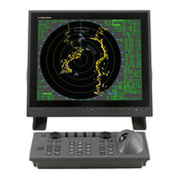
20” High resolution Multi-color LCD
Brand:
Furuno
| Category:
Marine Radar
| Size: 0.55 MB
Table of Contents
Data Display
4
Target Trails
5
Radar Map
5
Interconnection Diagram
7
Advertisement
Related Products
Furuno FAR-2117-D
Furuno FAR-2117-BB
Furuno FAR-2107(-BB)
Furuno FAR-2167DS
Furuno FAR-2137S-BB
Furuno FAR-2107 Series
Furuno FAR-2157-BB
Furuno FAR-2157-D
Furuno FAR21x7 & BB FAR28x7 Operator's BB FAR28x7
Furuno FAR-2107(-D) series
Furuno Categories
Marine Radar
Marine Equipment
Sonar
Monitor
GPS
More Furuno Manuals
Login
Sign In
OR
Sign in with Facebook
Sign in with Google
Upload manual
Upload from disk
Upload from URL