Furuno FAR-2157-BB Operator's Manual
Hide thumbs
Also See for FAR-2157-BB:
- Installation manual (111 pages) ,
- Operator's manual (305 pages) ,
- Operator's manual (299 pages)

Related Manuals for Furuno FAR-2157-BB


Summary of Contents for Furuno FAR-2157-BB
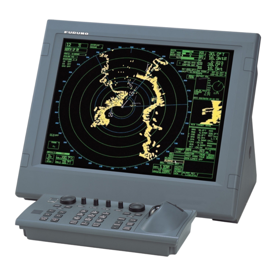
- Page 1 OPERATOR'S MANUAL MARINE RADAR FAR-2157(-BB) FAR-2167DS(-BB) Model (Fishing Specification) www.furuno.com...
- Page 2 The paper used in this manual is elemental chlorine free. ・FURUNO Authorized Distributor/Dealer 9-52 Ashihara-cho, Nishinomiya, 662-8580, JAPAN A : JAN 2011 Printed in Japan All rights reserved. C3 : AUG . 20, 2014 Pub. No. OME-35220-C3 ( GREG ) FAR-21X7/28X7(FISH)
- Page 3 (http://www.eiae.org/) for the correct method of disposal. How to discard a used battery Some FURUNO products have a battery(ies). To see if your product has a battery, see the chapter on Maintenance. Follow the instructions below if a battery is used. Tape the + and - terminals of battery before disposal to prevent fire, heat generation caused by short circuit.
- Page 4 Note: If the antenna unit is installed at a close distance in front of the wheel house, your administration may require halt of transmission within a certain sector of antenna revolution. This is possible. Ask your FURUNO representive or dealer to provide this feature. Radar model...
- Page 5 SAFETY INSTRUCTIONS WARNING WARNING ELECTRICAL SHOCK HAZARD Use the proper fuse. Do not open the equipment. Use of a wrong fuse can result in damage Only qualified personnel to the equipment or cause fire. should work inside the equipment. Keep heater away from equipment. Turn off the radar power Heat can alter equipment shape and melt switch before servicing the...
- Page 6 WARNING LABEL Warning labels are attached to the equipment. Do not remove any label. If a label is missing or damaged, contact a FURUNO agent or dealer about replacement. DISPLAY UNIT, PROCESSOR UNIT WARNING Name: Warning Label (1) To avoid electrical shock, do not remove cover.
- Page 7 TABLE OF CONTENTS FOREWORD ......................xi PROGRAM NUMBER ..................xiv SYSTEM CONFIGURATION................xv SPECIFICATIONS................... SP-1 1. RADAR OPERATION..................1-1 1.1 Turning on the Power ....................1-1 1.2 Transmitter ON ......................1-1 1.3 Control Unit ......................... 1-3 1.4 Main Menu........................1-5 1.5 Operation Using the On-Screen Boxes ...............
- Page 8 TABLE OF CONTENTS 1.21 Measuring the Bearing ....................1-33 1.21.1 Measuring the bearing..................1-33 1.21.2 Choosing true or relative bearing ..............1-35 1.22 Collision Assessment by Offset EBL ................1-36 1.22.1 How to assess risk of collision by the offset EBL ..........1-36 1.22.2 Choosing point of reference for origin point of offset EBL .......1-37 1.23 Measuring Range and Bearing Between Two Targets ..........1-38 1.24 Setting a Target Alarm....................1-39 1.24.1 How to set a target alarm zone................1-39...
- Page 9 TABLE OF CONTENTS 1.36 Noise Rejector......................1-70 1.37 Suppressing Second-trace Echoes ................1-71 1.38 Adjusting Brilliance of Screen Data ................1-72 1.39 Watch Alarm ......................1-73 1.40 Setting Up Nav Data....................1-74 1.41 Text Window Setup....................1-76 1.42 Customizing Operation ....................1-78 1.43 Alarms ........................
- Page 10 TABLE OF CONTENTS 3.7.2 Choosing ARP symbol (B, C and W types) .............3-10 3.7.3 ARP symbol brilliance..................3-10 3.7.4 ARP symbol color and size................3-11 3.7.5 Auto target track (A, B, C and W types) ............3-12 3.8 Displaying Target Data ....................3-13 3.8.1 Displaying individual target data..............3-13 3.8.2 Target list ......................3-15 3.9 Vector Modes ......................3-17...
- Page 11 TABLE OF CONTENTS 4.9 Past Position Display....................4-12 4.9.1 Displaying and erasing past position points, choosing past position plot interval...................... 4-12 4.9.2 Past position display attributes ............... 4-13 4.10 Lost Target......................... 4-14 4.11 ROT Setting....................... 4-15 4.12 Fusion of ARP and AIS Targets ................. 4-16 4.13 Own Ship’s Data......................
- Page 12 TABLE OF CONTENTS 5.13 Nav Lines ........................5-27 5.13.1 Entering new nav line ..................5-27 5.13.2 Editing nav lines ....................5-28 5.13.3 Nav line list ......................5-29 5.13.4 Erasing nav lines .....................5-30 5.13.5 Setting up nav lines ..................5-31 5.13.6 Displaying nav line, waypoint mark ..............5-33 5.14 Recording Data ......................5-35 5.14.1 Initializing memory (RAM) cards..............5-35 5.14.2 Recording data ....................5-36...
- Page 13 Series Congratulations on your choice of the FURUNO FAR-2157(-BB)/2167DS(-BB). We are confident you will see why FURUNO has become synonymous with quality and reliability. Since 1948, FURUNO Electric Company has enjoyed an enviable reputation for innovative and dependable marine electronics equipment. This dedication to excellence is furthered by our extensive global network of agents and dealers.
- Page 14 FOREWORD • Two types of trackball-equipped control units are available: RCU-014 (full keyboard) and the RCU-015 (palm control). The trackball is easy to use thanks to the ergonomically designed palm rest. • Simplified operation with point-and-click menu operation. • All functions are accessible by using the trackball alone. •...
- Page 15 FOREWORD Radar Type and Function Availability This radar series is available in five specification types to meet the requirements of Authorities, and function availability depends on specification type. The table below shows those functions which have limited availability. This manual provides descriptions for all functions in this radar series, and we have endeavored to denote in the text those functions which have limited availability.
- Page 16 PROGRAM NUMBER PC Board Program No. Version No. MAIN 035-9204 50.** 035-9202 01.** KEY(REMOTE) 035-9203 01.** ARPA 035-9212 01.** ** Minor modification...
- Page 17 SYSTEM CONFIGURATION See page xvi for detailed information about antenna units and radiators. With FURUNO-supplied monitor FAR-2167DS FAR-2157 ANTENNA UNIT ANTENNA UNIT RSB-106 RSB-111 RSB-107 RSB-112 POWER SUPPLY UNIT PSU-006 MONITOR UNIT DC spec. MU-201CR (20.1-inch) CONTROL UNIT MU-190 RCU-014...
- Page 18 SYSTEM CONFIGURATION Blackbox type FAR-2167DS-BB FAR-2157-BB ANTENNA UNIT ANTENNA UNIT RSB-111 RSB-106 RSB-112 RSB-107 VGA Monitor CONTROL UNIT RCU-014 POWER SUPPLY UNIT (Keyboard) PSU-006 RCU-015 (Trackball) Control Unit RCU-016 (Remote) PROCESSOR UNIT RPU-013 Sub Display Alarm External Monitor IEC-61162-1 Serial Data Navigator (INS, GPS, etc.)
- Page 19 SYSTEM CONFIGURATION Antenna unit FAR-2157 RSB-106 (18/22 rpm, 200 VAC, 3ø, 50Hz, 220 VAC, 3ø, 60 Hz) RSB-107 (22 rpm, 24 VDC) FAR-2167DS RSB-111 (21/26 rpm, 200 VAC, 3ø, 50Hz, 220 VAC, 3ø, 60Hz) RSB-112 (21/26 rpm, 380 VAC, 3ø, 50Hz, 440 VAC, 3ø, 60Hz) Radiator FAR-2157 XN4A, XN5A...
- Page 20 SYSTEM CONFIGURATION This page intentionally left blank. xviii...
Need help?
Do you have a question about the FAR-2157-BB and is the answer not in the manual?
Questions and answers