Furuno FAR-2137S Installation Manual
Marine radar/arpa
Hide thumbs
Also See for FAR-2137S:
- Service manual (690 pages) ,
- Operator's manual (312 pages) ,
- Manual (300 pages)
Table of Contents
Advertisement
Advertisement
Table of Contents

Related Manuals for Furuno FAR-2137S


Summary of Contents for Furuno FAR-2137S
- Page 1 MARINE RADAR/ARPA FAR-2137S/2837S/2137S-BB PRINTED IN JAPAN...
- Page 2 *00014868801* *00014868801* *00014868801* *00014868801* ( ( TATA TATA ) ) FAR-2137S/BB/2837S FAR-2137S/BB/2837S * 0 0 0 1 4 8 6 8 8 0 1 * * 0 0 0 1 4 8 6 8 8 0 1 * *IME35210B00* *IME35210B00*...
- Page 3 Serious injury or death can result if some- antenna revolution. This is possible–Ask one falls from the radar antenna mast. your FURUNO representative or dealer to provide this feature. Turn off the power at the mains switch- board before beginning the installation.
- Page 4 CAUTION WARNING Be sure that the power supply is After fixing the antenna radiator, be sure compatible with the voltage rating of to remove the guide pins. the equipment. Injury may result if the guide pins loosen Connection of an incorrect power supply and fall.
-
Page 5: Table Of Contents
TABLE OF CONTENTS EQUIPMENT LISTS ..................... iv SYSTEM CONFIGURATION................vi 1. MOUNTING ....................1-1 1.1 Antenna Unit ........................ 1-1 1.2 Monitor Unit........................1-7 1.3 Power Supply Unit...................... 1-11 1.4 Control Unit........................ 1-12 1.5 Processor Unit ......................1-15 2. WIRING ......................2-1 2.1 Interconnection ...................... -
Page 6: Equipment Lists
220 VAC, 3φ, 50 Hz Antenna RSB-101 220 VAC, 3φ, 60 Hz Chassis for HSC RSB-102 440 VAC, 3φ, 60 Hz Power Supply Unit PSU-007 MU-201CR For FAR-2137S Monitor Unit MU-231CR For FAR-2837S Processor Unit RPU-013 AC type RCU-014 Standard type Control Unit RCU-015... -
Page 7: Optional Equipment
Optional Equipment Name Type Code No. Remarks Gyro Converter GC-10-2 See chapter 4. 000-080-440 Performance Monitor PM-51 Mandatory for IMO radar 000-081-261 For processor unit, RU-1803 440 VAC 100 VAC For de-icer , 110/115/220/230 VAC RU-3305 100 VAC For RSB-098/099, Transformer Unit RU-5693 110 V... -
Page 8: System Configuration
220-230 VAC , 50-60 Hz φ , 50-60 Hz *: For FAR-2137S-BB, a monitor unit is prepared by user. See page 1-7. **: Used for antenna cable more than 100 m. ***: Not available for HSC spec. Category of Units... -
Page 9: Mounting
1. MOUNTING Antenna Unit Mounting considerations • The antenna unit is generally installed either on top of the wheelhouse, on the radar mast, or on a suitable platform. Locate the antenna unit where there is a good all-round view. • No funnel, mast or derrick should be within the vertical beamwidth of the antenna unit in the bow direction, especially zero degrees ±... - Page 10 1. MOUNTING Installation precaution for S-band antenna unit If an S-band antenna unit is mounted near the end of a platform to provide sufficient rotation clearance for the radiator, the antenna unit, because of its weight, swings up and down by ship’s vibration and rolling.
- Page 11 1. MOUNTING Antenna unit assembling The antenna radiator and the antenna housing are shipped in separate packages. Assemble them as below. The antenna unit may be assembled before hosting it to the mounting platform. However, do not lift the antenna unit by the radiator. Antenna unit assembling procedure 1.
- Page 12 1. MOUNTING How to lift the antenna unit 1. Fix the antenna radiator to the antenna unit chassis as shown on page 1-4. 2. Attach the lifting fixtures and collars as shown below. 3. Position the radiator as shown below and arrange the ropes A and B. Lifting fixture Supplied as accessories.
- Page 13 1. MOUNTING Fastening the antenna unit to the mounting platform See the figure on the next page for antenna unit mounting. 1. Referring to the antenna outline drawing, drill eight fixing holes of 15 mm in diameter in the radar mast platform or the deck. •...
- Page 14 1. MOUNTING Seal washer Corrosion proof rubber Use two nuts. (Torque 63.5Nm) Ground terminal G1_1/4-A Set corrosion-proof rubber mat, bolt antenna unit to mounting location, and coat exposed hardware with silicone sealant. Hex bolt Flat washer Flat washer Ground wire Spring washer Coat with silicone sealant after Hex nut...
-
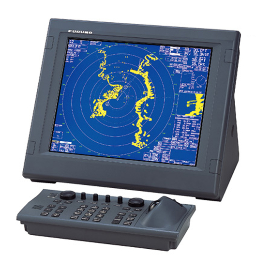
Page 15: Monitor Unit
The monitor unit can be flush mounted in a console panel, or mounted on a desktop using the optional accessories. Note: FAR-2137S-BB has no monitor unit. Prepare a suitable one locally. Recommended monitor: SXGA (1280x1024), aspect ratio 5:4 Mounting considerations When selecting a mounting location, keep in mind the following points: •... - Page 16 1. MOUNTING ± 4-φ8 FIXING HOLES 4-FIXING HOLES ± Monitor unit MU-231CR (For FAR-2837S) Flush mounting of monitor unit Panel hook Panel cover Fixing screw Attaching panel hook and panel cover Note: If you need to remove the monitor unit from the mounting panel, remove the four panel covers with your fingernail and use two panel hooks supplied as accessories to lift the monitor unit.
- Page 17 1. MOUNTING Desktop mounting Use the optional accessories to mount the monitor unit on a desktop. • For FAR-2137S: FP03-09820 (Code No.: 008-535-560) • For FAR-2837S: FP03-09830 (Code No.: 008-536-020) Contents of FP03-09820/09830 Name Type Code No. Remarks Hanger L...
- Page 18 1. MOUNTING Hanger (L) M12 bolts for fixing (Torque 63.5Nm) (Dockyard supply) Hanger stay Hanger (R) Panel cover Plastic rivet Flat Washer M10 Hex bolt (M6x25) (Torque 7.6Nm) Spring Washer M10 Hex bolt M10x30 (Torque 36.5Nm) Hole plug Panel cover To remove this, insert fingernail in groove.
-
Page 19: Power Supply Unit
1. MOUNTING Power Supply Unit The Power Supply Unit PSU-007 does not contain usual operating controls. Therefore, it can be installed in any recessed place either in vertical or horizontal position. (For the console mount display unit, the PSU-007 can be installed inside the console.) However, select a dry and well-ventilated location and observe the compass safe distance to prevent deviation of a magnetic compass. -
Page 20: Control Unit
1. MOUNTING Control Unit The control unit may be mounted on a tabletop, with or without the KB fixing metal (supplied), which mounts the control unit at an angle. Mounting considerations When selecting a mounting location, keep in mind the following points: •... - Page 21 1. MOUNTING Fixing without KB fixing metal 1. Drill four mounting holes of 5 mm diameter referring to the outline drawing at the back of this manual. 2. Fix the control unit with four screws (M4) from under side of the tabletop. (The M4 screws with a sufficient length for the thickness of the tabletop should be provided locally.) 4-M4 (Fixing holes)
- Page 22 1. MOUNTING 1. Prepare a cutout in the mounting location as shown in the figure below. ±2 170±2 ±2 ±2 For RCU-014 For RCU-015 and RCU-016 2. Set the control unit to the cutout. 3. Attach the mounting plate to the control unit with four screws from the rear side. 4.
- Page 23 1. MOUNTING To connect RCU-016 in series with RCU-014 1. Pass the cable derived from RCU-016. 2. Connect the connector of the cable to J502. 3. Clamp the copper part of the cable with the cable clamp. Inside of RCU-014 1-15...
- Page 24 1. MOUNTING To change the cable entry To change the cable entry from the side (default) to the bottom, modify the unit as shown below. Bottom of the unit Screw M3X8 (Torque 0.78Nm) 2. Pull out the cable. Cable clamp 3.
-
Page 25: Processor Unit
1. MOUNTING Processor Unit Mounting considerations When selecting a mounting location, keep in mind the following points: • Locate the processor unit away from heat sources because of heat that can build up inside the cabinet. • Locate the equipment away from places subject to water splash and rain. •... - Page 26 1. MOUNTING This page is intentionally left blank. 1-18...
-
Page 27: Wiring
2. WIRING Interconnection Antenna unit Monitor unit TB801 TB802 POWER SUPPLY Junction Box UNIT PSU-007 RJB-001** 220 VAC, 3φ, 60 Hz RW-9600 200 VAC, 3φ, 50 Hz 15/30/40/50 m (Max.100 m) 440 VAC, 3φ, 60 Hz 380 VAC, 3φ, 50 Hz DPYC-2.5 For HSC Control unit... -
Page 28: Antenna Unit
2. WIRING Antenna Unit G3/4-C G1-A Gland for power cable Antenna motor switch G1_1/4-A G1_1/4-A Gland for signal cable (RW-9600) Antenna unit, bow view 1. Open the right side cover on the antenna unit with the hex wrench. 2. Unfasten the cable gland for the signal cable and remove the gasket, flat washers and blind lid. - Page 29 2. WIRING TB801 TB801 Coaxial cable TB board TB802 Pass the signal cable Clamp shield of coaxial cable. RW-9600. Grounding point for the shield. Antenna unit, port side view 6. Confirm that armor is grounded between two flat washers. 7. Coat the screw part of the clamping gland with silicone sealant and tighten it. 8.
- Page 30 2. WIRING Fabricating power cable TPYCY-2.5 1. Open the left side cover on the antenna unit with the hex wrench. 2. Fabricate the cable as shown below. Use TPYCY-2.5 (Japan Industry Standard) cable or equivalent. Cable TPYCY-2.5 ∅ = 15.5 mm Sheath Approx.
- Page 31 2. WIRING Terminal board Pass the power for power cable supply cable here. Antenna unit, left view Connect crimp-lug to the terminal block referring to the interconnection diagram. 9. Attach the cover. 10. Seal the cable gland with putty.
-
Page 32: Monitor Unit
2. WIRING Monitor Unit Two cables are terminated at the display unit: the signal cable from the processor unit (5 m or 10 m cable) and the power cable from the ship’s mains. The signal cable comes with a connector preattached to it for connection to the display unit. Fabricate the power cable as below. -
Page 33: Processor Unit
2. WIRING Processor Unit Four cables are terminated at the processor unit: the antenna unit cable, display unit cable, control unit cable and the power cable. Cables other than the power cable come with a connector preattached to them for connection to the processor unit. Fabricate the power cable as below. - Page 34 2. WIRING Connection of cables The power cable is connected to the terminal board on the rear panel and the signal cable from the Monitor unit is connected to the DVI-D connector. Other cables are connected to the printed circuit board 03P9342. Power cable clamp Monitor unit Power cable terminal board...
- Page 35 2. WIRING Location of connectors Open the processor unit as follows and the 03P9342 board appears. Cable clamp 03P9342 J608 J621 J612 Gyro converter board External alarm or AD-100 J607 Speed log J620 J606 J611 Track control Navigator J619 J605 J603 ECDIS Gyro converter board...
- Page 36 2. WIRING Cable fabrication for the cables connected to the 03P9342 board • Signal cable RW-9600 (Between antenna unit and processor unit) Vinyl sheath Armor Shield After exposing cores, Vinyl tape wind shield around the armor. 5 10 Coaxial cable Clamp here by cable clamp.
- Page 37 2. WIRING Connection of Sub-display A conventional remote display and/or FAR-2107 series radar can be connected to J617 and J618 in the processor unit as a sub-display. However, the control for GAIN and STC are different depending on J617 and J618. Refer to the table to connect sub-displays. Port Conventional remote FAR-2107 series radar...
-
Page 38: Power Supply Unit
2. WIRING Power Supply Unit Wire the unit as shown in the interconnection diagram. Thermal relay Relay K2: Connect input line. XK1: Connect output line. TB1: Connect control line. Cable clamp: Clamp the armors of the cable. Power supply unit PSU-007 Changing AC Power Specification of Processor Unit To change AC power specification between 100 VAC and 220 VAC, add or remove jumper... - Page 39 2. WIRING Cover of PWR board Fuse PWR board Upper part of processor unit (SPU assembly omitted) J105 J106 (P)HV PWR board J104 J103 (OVER) J101 P108/J108 AC FIL 8 7 6 5 4 3 2 1 Jumper connector (VH10P) How to adjust the overvoltage detection circuit: 1.
- Page 40 2. WIRING This page is intentionally left blank. 2-14...
-
Page 41: Setting And Adjustment
3. SETTING AND ADJUSTMENT DIP Switch Setting The processor unit is shipped for model FAR-2137S. If your model is FAR-2837S/2137S-BB, change the DIP switch setting as follows. 1. Remove the top cover of the processor unit. 2. Open the SPU assembly block and remove the shield cover. -
Page 42: Initializing Tuning
3. SETTING AND ADJUSTMENT Initializing tuning 1. Transmit the radar on 48 nm range and rotate the GAIN knob to show 70-80 of the gain bar. 2. Roll the trackball to choose the MENU box at the right side of the screen and then push the left button. -
Page 43: Heading Alignment
3. SETTING AND ADJUSTMENT Heading Alignment You have mounted the antenna unit facing straight ahead in the direction of the bow. Therefore, a small but conspicuous target dead ahead visually should appear on the heading line (zero degrees). In practice, you will probably observe some small bearing error on the display because of the difficulty in achieving accurate initial positioning of the antenna unit. - Page 44 3. SETTING AND ADJUSTMENT 7. Press [0] key to show the [INITIALIZE] menu. [INITIALIZE] 1 BACK 2 [ECHO ADJ] 3 [SCANNER] 4 [INSTALLATION] 5 [OWN SHIP INFO] 6 [ARP PRESET] 7 [NETWORK] 8 [OTHER] Note: See next page to access the INITIALIZE menu with the trackball style control unit RCU-015.
- Page 45 3. SETTING AND ADJUSTMENT How to Access the Installation Mode with the RCU-015 Trackball Style Controller 1. By using the trackball, move the pointer until it highlights the MENU box as shown. DO NOT CLICK the menu box, just leave the arrow over the menu.
-
Page 46: Adjustment Sweep Timing
3. SETTING AND ADJUSTMENT Adjustment Sweep Timing Sweep timing differs with respect to the length of the signal cable between the antenna unit and the processor unit. Adjust sweep timing at installation to prevent the following symptoms: • The echo of a “straight” target (for example, pier), on the 0.25 m range, will appear on the display as being pulled inward or pushed outward. -
Page 47: Suppressing Main Bang
3. SETTING AND ADJUSTMENT Suppressing Main Bang If main bang appears at the screen center, suppress it as follows. 1. Transmit the radar on a long range and then wait ten minutes. 2. Adjust gain to show a slight amount of noise on the display. 3. -
Page 48: Other Settings
3. SETTING AND ADJUSTMENT Other Settings ECHO menu setting Open the [ECHO ADJ] menu as described on page 3-2. [ECHO ADJ] 1 BACK 2 CABLE ATT ADJ AUTO/MANUAL 3 HD ALIGN 000.00 4 TIMING ADJ 5 MBS 6 DEFAULT ANT HEIGHT 5/7.5/10/15/20/ 25/30/35/40/45/ more 50 m... - Page 49 To erase the area, enter 0 for both the START and ANGLE sections. The setting range of START is 0 to 359° and ANGLE is 0 to 180°. ANT REVOLUTION Not used for FAR-2137S/2837S/2137S-BB. ANT SW and ANT STOPPED This is used for antenna maintenance by serviceman.
- Page 50 MODEL Confirm the model of your radar. If the setting of this item is different from your model (combination of the antenna unit), the radar functions abnormally. Select “30 UP” for FAR-2137S/ 2837S/ 2137S-BB. 3-10...
- Page 51 3. SETTING AND ADJUSTMENT TYPE Choose type of radar: IMO, A, B, or C. ON TIME and TX TIME These items show number of hours the radar has been turned on and transmitted, respectively. Value can be changed; for example, after replacing magnetron TX Time can be reset to 0.
- Page 52 3. SETTING AND ADJUSTMENT OWN SHIP INFO menu setting Open the OWN SHIP INFO menu by pressing [5] key on the INITIALIZE menu. [OWNSHIP INFO] 1 BACK 2 LENGTH/WIDTM LENGTH 100 m WIDTH 50 m 3 SCANNER POSN BOW 0 m LEFT 0 m 4 GPS1 ANT POSN BOW 0 m...
- Page 53 3. SETTING AND ADJUSTMENT ARPA PRESET menu setting Open the ARPA PRESET menu by pressing [6] key on the INITIALIZE menu. [TRACK PRESET] [ARP PRESET] 1 BACK 1 BACK 2 GATE SIZE [ACQ PRESET] 2 TTM OUTPUT S/ M /L/LL OFF/REL/TRUE 1 BACK 3 FILTER RESPONSE...
- Page 54 3. SETTING AND ADJUSTMENT AUTO ACQ CORRE Set the correlation count of automatic acquisition. The setting range is 3 to 10. AUTO ACQ WEED Set the cancel count of automatic acquisition. The setting range is 1 to 5. GATE SIZE Set the gate size among S, M, L, or LL.
- Page 55 3. SETTING AND ADJUSTMENT OTHER menu setting Open the OTHER menu by pressing [8] key on the INITIALIZE menu. [OTHERS] 1 BACK 2 DEMO ECHO OFF/EG/SPU/PC 3 EAV/ w/o GYRO OFF/ON 4 ARP SELECT ARPA/ATA 5 INS OFF/SERIAL/LAN EAV w/o GYRO If a gyrocompass is not connected, choose the echo average function, ON (working) or OFF (no working).
- Page 56 3. SETTING AND ADJUSTMENT This page is intentionally left blank. 3-16...
-
Page 57: Installing Optional Equipment
4. INSTALLING OPTIONAL EQUIPMENT Gyro Converter GC-10 The Gyro Converter GC-10, incorporated inside the processor unit, converts analog gyrocompass reading into digital coded bearing data for display on the radar screen. This section explains how to install the GC-10 (mainly consisting of the GYRO CONVERTER board) and set it up according to gyrocompass connected. - Page 58 4. INSTALLING OPTIONAL EQUIPMENT 2. Fasten the GYRO CONVERTER board in the processor unit with five washer head screws and male connector 231-607/019-FUR (called J602) with two screws. Screw M3X8 5 pcs GYRO CONVERTER board (Torque 0.78Nm) 64P1106A Screw M2.6X10 2 pcs (Torque 0.39Nm) Connector (231) 231-107/026-FUR...
- Page 59 4. INSTALLING OPTIONAL EQUIPMENT 4. Connect the GYRO CONVERTER board and J602 with two connector assemblies 03-2089 and 03-2090. Wiring for WAGO connector Press downward. Terminal opener Connection for J602 Connection for P608 P608 From J4 From J5 WAGO connector Twist Wire Procedures...
- Page 60 4. INSTALLING OPTIONAL EQUIPMENT 5. Confirm gyrocompass specifications and set up the DIP switches and jumper wires on the GYRO CONVERTER board according to gyrocompass connected: • Setting jumper wires and DIP switches by gyrocompass specifications: page 4-5 • Setting jumper wires and DIP switches by make and model of gyrocompass: page 4-7 •...
- Page 61 4. INSTALLING OPTIONAL EQUIPMENT Connection of external power supply An external power supply is necessary when the repeater signal is step-by-step type and the step voltage is below 20 V or output voltage is less than 5 W. 1. Cut jumper wire JP1 on the GYRO CONVERTER board when an external power supply is used.
- Page 62 4. INSTALLING OPTIONAL EQUIPMENT Setting method 1: DIP switch settings and gyrocompass specifications 1) Gyrocompass type 2) Frequency Gyrocompass Frequency Remarks type #1, #2, AC synchronous 50/60 Hz synchronous pulsating current #2, #3, AC synchronous 400 Hz synchronous pulsating current #4, #5, AC synchronous DC step...
- Page 63 4. INSTALLING OPTIONAL EQUIPMENT Setting method 2: by make and model of gyrocompass a t l a t l a t l a t l ) - ( i a l a t l a t l CMZ-700 DC step OFF Remo- 24V 180x COM(+), 3-wire(-)
- Page 64 4. INSTALLING OPTIONAL EQUIPMENT Location of DIP switches, jumper wires on the GYRO CONVERTER board JP5, JP4 (Supply voltage) (Rotor voltage) (Stator voltage) DIP switch 64P1106 (Gyro type) (Data output port #6) (Data output port #5) (Data output port #4) DIP switch JP6, JP7 (AD format...
-
Page 65: Memory Card Interface Unit
4. INSTALLING OPTIONAL EQUIPMENT Memory Card Interface Unit Mounting considerations When selecting a mounting location, keep in mind the following points: • Locate the memory card interface unit away from heat sources because of heat that can build up inside the cabinet. •... - Page 66 4. INSTALLING OPTIONAL EQUIPMENT Desktop mount For desktop mount, the optional desktop mount kit FP03-10201 is required. Refer to the end of this manual. 1. Fix the mounting bracket 19-023-3081 on the unit with four screws. 2. Mount the above assembly on a desktop with four tapping screws. Console mount For console mount, the optional console mount kit FP03-10202 is required.
- Page 67 4. INSTALLING OPTIONAL EQUIPMENT Memory card IF unit MJ-A3SPF0015-100 (10 m) No.1 J614 12 VDC Processor two mini-cards unit FR-FTPC-CY (10/20/30 m) (straight) NETWORK NETWORK FR-FTPC-CY (10/20/30 m) (straight) Switching hub FR-FTPC-CY No.2 (10/20/30 m) Processor (straight) unit HUB-100 (option) No.3 Processor FR-FTPC-CY (10/20/30 m) (straight)
-
Page 68: Dvi-Rgb Conversion Kit
4. INSTALLING OPTIONAL EQUIPMENT DVI-RGB Conversion Kit This information provides the procedure necessary for the installation of the DVI-RGB conversion kit. This kit is installed in the processor unit to enable connection of an RGB monitor or VDR (Voyage Data Recorder). Name: DVI-RGB conversion kit Type:... - Page 69 4. INSTALLING OPTIONAL EQUIPMENT Remove the top cover and open the upper part of the processor unit. DVI-D port (Connect DVI cable at step 13) Processor unit 2. Fix the 03P9229A board (RGB-BUFF) with four screws. (See the figure below.) 3.
- Page 70 4. INSTALLING OPTIONAL EQUIPMENT DVI-RGB Conversion board J3 (Connect DVI cable at step 10.) Fixing the DVI-RGB conversion board 6. Attach the 10-pin connector from J1 on the 03P9229A board to J9 on the DVI-RGB board. 7. Attach the connector assembly 03-2092 to J4 on the DVI-RGB conversion board. 8.
-
Page 71: Bnc Connector Converter
4. INSTALLING OPTIONAL EQUIPMENT 4.4 BNC Connector Converter To connect the VR-5000 (FURUNO Voyage Data Recorder) to this radar, the DVI-RGB conversion kit (mentioned at previous paragraph) and the BNC connector converter are required. Also VGA cable (between the processor unit and the BNC connector converter) and five 75 ohms coaxial cables (between the BNC connector converter and VR-5000) are required. -
Page 72: Switching Hub
4. INSTALLING OPTIONAL EQUIPMENT 4.5 Switching Hub If two or more processor units and memory card IF units are installed, the Switching Hub HUB-100 is required. Interconnection 100 V to 230 VAC 03S9722 Switching hub HUB-100 8 ports Card IF unit CU-200 No.1 Processor unit... -
Page 73: Input/Output Data
5. INPUT/OUTPUT DATA Input and output data are shown in the table below. Note: This radar accepts position data fixed by WGS-84 geodetic datum. Set the datum to WGS-84 on the EPFS (GPS, etc.) connected to this radar. If other type of datum is input, the error message "DATUM"... - Page 74 5. INPUT/OUTPUT DATA IEC 61162 input sentence and priority Contents Sentence and priority Speed (STW) VBW>VHW Speed (SOG) Speed (position) VTG>RMC Heading (True) HDT* Position GGA>GLL>RMC>RMA Waypoint BWR>BWC>RMB Date Depth DPT>DBT>DBS Temperature Wind *: HDT is IEC61162-2. OTHERS IEC6112-1 ed2. IEC 61162 output sentence Contents Sentence...
- Page 75 1.コ-ド番号末尾の[**]は、選択品の代表型式/コードを表します。 CODE NUMBER ENDED BY "**" INDICATES THE NUMBER OF TYPICAL MATERIAL.
- Page 76 A-2a...
- Page 77 A-2b...
- Page 79 1.コ-ド番号末尾の[**]は、選択品の代表型式/コードを表します。 CODE NUMBER ENDED BY "**" INDICATES THE NUMBER OF TYPICAL MATERIAL.
- Page 80 008-254-590...
- Page 81 1.コ-ド番号末尾の[**]は、選択品の代表型式/コードを表します。 CODE NUMBER ENDED BY "**" INDICATES THE NUMBER OF TYPICAL MATERIAL.
- Page 83 FAR-2117 series...
- Page 84 1.コード末尾に[**]の付いたユニットは代表の型式/コードを表示しています。 DOUBLE ASTERISK DENOTES COMMONLY USED EQUIPMENT. 2.予備品は、AC用,DC用で選択願います。 CHOOSE SPARE PARTS DEPENDING ON AC OR DC POWER.
- Page 85 A-10...
- Page 86 A-11 1.コード末尾に[**]の付いたユニットは代表の型式/コードを表示しています。 DOUBLE ASTERISK DENOTES COMMONLY USED EQUIPMENT. 2.予備品は、AC,DCで選択願います。 CHOOSE SPARE PARTS DEPENDING ON AC OR DC POWER.
- Page 87 A-12 1.コード末尾に[**]の付いたユニットは代表の型式/コードを表示しています。 DOUBLE ASTERISK DENOTES COMMONLY USED EQUIPMENT. 2.予備品は、(*1)のSP03-14404(AC100用)の他にSP03-14405(AC220用),SP03-14406(DC100用)から選択して下さい。 CHOOSE SPARE PARTS FROM AMONG SP03-14404 *1 (FOR 100VAC SPEC.), SP03-14405(FOR 220VAC SPEC.) AND SP03-14406(FOR 24VDC SPEC). 3.工事材料は、(*2)のCP03-25602(AC用)の他に、CP03-25603(DC用)から選択してください。 CHOOSE INSTALLATION MATERIALS FROM CP03-25602 *2(FOR AC SPEC.) AND CP03-25603(FOR DC SPEC.) APPROPRIATELY.
- Page 88 A-13...
- Page 89 A-14...
- Page 90 A-15...
- Page 91 A-16...
- Page 92 A-17 (*1)は、FP03-09820用です。 *1: FOR FP03-09820. (*2)は、FP03-09830用です。 *2: FOR FP03-09830.
- Page 93 A-18...
- Page 94 A-19...
- Page 95 A-20 CU-200...
- Page 96 A-21 Option For CU-200 Desktop mount kit...
- Page 97 A-22 For CU-200 Option Console mount kit...
- Page 98 A-23...
- Page 99 A-24 Coupling pedestal kit Option RCU-014 + MU-201CR...
- Page 100 A-25 Coupling pedestal kit Option RCU-014 + MU-231CR...
- Page 101 A-26 DVI-RGB conversion kit Option...
- Page 102 A-27 For LAN cable kit Option...
- Page 103 A-28 MU-201CR AC set MU-231CR AC set...
- Page 104 A-29 RPU-013 100 VAC set...
- Page 105 A-30 RPU-013 220 VAC set...
- Page 106 A-31 GC-10...
- Page 109 Takahashi T...
- Page 116 D-10...
- Page 117 D-11...
- Page 118 D-12...
- Page 119 D-13...
- Page 120 D-14...
- Page 121 D-15...
- Page 122 D-16...
- Page 123 D-17...
- Page 124 D-18...
- Page 125 D-19...
- Page 126 D-20...
- Page 127 D-21...
- Page 128 D-22...
-
Page 129: Interconnection Diagram
*1 *6 BNCコネクタコンバータ BREAKER DSUB-BNC-1 モニター部 DPYC-2.5 100-240VAC MONITOR UNIT MU-201CR (FAR-2137S) MU-231CR (FAR-2837S) USER SUPPLY FOR FAR-2137S-BB IV-8sq. *1 NOTE 注記 保護アース PE *1 : SHIPYARD SUPPLY *1 : 造船所手配 *2 : OPTION *2 : オプション *3 : USER SUPPLY *3 : ユーザー手配...
Need help?
Do you have a question about the FAR-2137S and is the answer not in the manual?
Questions and answers