SCHUNK TANDEM KSP3 Assembly And Operating Manual
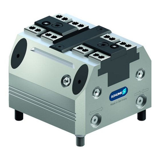
Clamping force block
Hide thumbs
Also See for TANDEM KSP3:
- Assembly and operating manual (55 pages) ,
- Assembly and operating manual (52 pages) ,
- Assembly and operating manual (44 pages)

Related Manuals for SCHUNK TANDEM KSP3


Summary of Contents for SCHUNK TANDEM KSP3
- Page 1 Translation of Original Operating Manual TANDEM Clamping Force Block KSP3, KSP3-LH, KSP3-F Assembly and Operating Manual...
- Page 2 Imprint Imprint Copyright: This manual is protected by copyright. The author is SCHUNK GmbH & Co. KG. All rights reserved. Technical changes: We reserve the right to make alterations for the purpose of technical improvement. Document number: 1463318 Version: 02.00 | 05/01/2022 | en...
-
Page 3: Table Of Contents
Table of Contents Table of Contents General ........................5 About this manual ....................5 1.1.1 Presentation of Warning Labels ..............5 1.1.2 Applicable documents ................5 1.1.3 Sizes ......................6 Warranty ......................... 6 Scope of Delivery ....................6 Basic safety notes ....................7 Intended use...................... - Page 4 Table of Contents Maintenance and care .................... 28 Notes ........................28 Maintenance and lubrication intervals ..............28 Greasing areas / lubricants ................... 28 Maintenance work ....................29 7.4.1 Lubricate ....................29 7.4.2 Basic cleaning.................... 30 7.4.3 Leak test ....................35 7.4.4 Assembly device ..................
-
Page 5: General
• General terms of business * • Catalog data sheet of the purchased product * The documents labeled with an asterisk (*) can be downloaded from schunk.com. 02.00 | KSP3, KSP3-LH, KSP3-F | Assembly and Operating Manual | en | 1463318... -
Page 6: Sizes
General 1.1.3 Sizes This operating manual applies to the following sizes: • KSP3 64, 100, 140, 160, 250 • KSP3-LH plus 64, 100, 140, 160, 250 • KSP3-F plus 64, 100, 140, 160, 250 1.2 Warranty The warranty period is 24 months after delivery date from factory or 500 000 cycles*, if it is used as intended, under the following conditions: •... -
Page 7: Basic Safety Notes
Use of unauthorized spare parts Using unauthorized spare parts can endanger personnel and damage the product or cause it to malfunction. • Use only original spare parts or spares authorized by SCHUNK. 2.5 Use of special chuck jaws Requirements of the chuck jaws 02.00 | KSP3, KSP3-LH, KSP3-F | Assembly and Operating Manual | en |... -
Page 8: Environmental And Operating Conditions
Basic safety notes When using special chuck jaws, please observe the following rules: • The chuck jaws should be designed to be as low as possible. The clamping point must be as close as possible to the housing. (clamping points at a greater distance cause higher surface pressures in the jaw guidance and can significantly reduce the clamping force.) •... -
Page 9: Personal Protective Equipment
Basic safety notes Qualified personnel Due to its technical training, knowledge and experience, qualified personnel is able to perform the delegated tasks, recognize and avoid possible dangers and knows the relevant standards and regulations. Instructed person Instructed persons were instructed by the operator about the delegated tasks and possible dangers due to improper behaviour. -
Page 10: Transport
Basic safety notes IMPORTANT! Following a longer shutdown period (more than approx. 6 hours), always re-tension the clamping device in order to compensate for the setting properties of the clamping situation or possible pressure losses and the resulting loss of clamping force. 2.10 Transport Handling during transport Incorrect handling during transport may impair the product's... -
Page 11: Protection During Handling And Assembly
Basic safety notes • Disconnect power sources before installation, modification, maintenance, or calibration. Ensure that no residual energy remains in the system. • Do not reach into the open mechanism or movement area of the product during operation. 2.13.1 Protection during handling and assembly Incorrect handling and assembly Incorrect handling and assembly may impair the product's safety and cause serious injuries and considerable material damage. -
Page 12: Notes On Particular Risks
Basic safety notes • To avoid accidents and/or material damage, human access to the movement range of the machine must be restricted. Limit/ prevent accidental access for people in this area due through technical safety measures. The protective cover and protective fence must be rigid enough to withstand the maximum possible movement energy. - Page 13 Basic safety notes WARNING Danger of crushing due to the chuck jaws approaching the workpiece during the clamping procedure when loading and unloading manually. Prioritize automated loading • Do not reach between the workpiece and the chuck jaw • during the clamping procedure WARNING Risk of injury due to accidental actuation when working on the product...
-
Page 14: Technical Data
Technical data 3 Technical data Installation position Operating temperature +5°C to +60°C Noise emission [dB(A)] ≤70 Pressure medium Compressed air, compressed air quality according to ISO 8573-1: 7:4:4 KSP3 Designation Stroke per jaw [mm] Clamping force* at max. pressure 4.5/5.5 18/22 30/36 45/54... - Page 15 Technical data KSP3-F Designation max. jaw height [mm] Weight [kg] Clamping force is the arithmetic sum of the individual forces occurring at the chuck jaws at distance "H" (see also catalog). End position spread after 100 consecutive strokes. When using an ABP-A base plate, the maximum pressure must be limited to 7 bar .
- Page 16 Technical data Optional Z variant ±0.01 mm to clamping center Clamping sleeve ±0.04 mm to clamping center Clamping sleeve fitting screw ±0.02 mm to clamping center Only with variant "PM" 02.00 | KSP3, KSP3-LH, KSP3-F | Assembly and Operating Manual | en | 1463318...
-
Page 17: Tightening Torques For Screws
Tightening torques for screws 4 Tightening torques for screws Tightening torques to mount the clamping system on the machine table (screw quality 10.9) Screw size M4 M5 M6 M8 M10 M12 M14 M16 M18 M20 M22 M24 Tightening torque 120 160 200 290 400 500 (Nm) Tightening torque for mounting top jaws on the TANDEM clamping force block (screw quality 12.9) -
Page 18: Assembly And Connection
Assembly and connection 5 Assembly and connection The numbers shown for individual components refer to the illustrations for assembly or connections of the clamping force block and to the "Assembly Drawings" chapter. } 9 [/ 42] WARNING Danger of crushing due to the product approaching the machine table during assembly. -
Page 19: Mounting The Clamping Block On The Base Plate
Assembly and connection NOTE • For vertical installation, the openings of the coolant drain (V) must always face downwards • Surface "X" is parallel to the guideway of the base jaws (item 2) so the clamping force block can be aligned on the machine table or to check the positioning. - Page 20 Assembly and connection NOTE: If the clamping force block and base plate are ordered separately, the screws, O-rings and clamping sleeves for assembling the parts are included in the accessory kit that comes with the clamping force block. • Do not open the connections on the front of the clamping force block (I, II), or seal them with suitable dummy plugs (M5 or G1/8").
-
Page 21: Connecting The Clamping Force Block
Assembly and connection The clamping force block has two more base connections (6/7) for direct lubrication through the machine table. These connections come sealed on delivery with set-screws (item 62). 5.3 Connecting the clamping force block Hose-free direct connection Clamping system Adapter O-ring... -
Page 22: Supply Lines
Assembly and connection 5.3.1 Supply lines The clamping force block has four air connections: I, II, III, IV. Two connections for OPEN (I and III) and two connections for CLOSE (II and IV). Which of the two air connections has to be opened for actuation depends on the application: •... -
Page 23: Air Coupling In Top Jaw (Variant "Pm")
Assembly and connection 5.3.3 Air coupling in top jaw (variant "PM") An air coupling in top jaw 1 is integrated via connection 2 on the bottom and an air coupling in top jaw 2 via connection 3. Work surface Size Dimension KTR-H KTR KTR-H KTR... - Page 24 Assembly and connection In doing so, the transfer dimensions ØC, D, E and F must be observed. Dynamic pressure monitoring of the workpiece flat work surface For this purpose, the customer must provide the top jaw with a Ø2 mm monitoring hole on the workpiece flat work surface. This ensures that the escaping air pressure can be released up to where contact is made with the mounted workpiece and that a differential pressure measurement can be carried out via a...
-
Page 25: Pneumatic Circuit Diagram
Assembly and connection 5.3.4 Pneumatic circuit diagram Circuit symbols Actuation 5/3 directional control valve, center position ventilated 3/2 directional control valve Pressure switch Pressure gauge Flow control valve Compressed air supply ← → Jaw stroke "open" → ← Jaw stroke "close" Dynamic pressure monitoring for jaw end position "open"... -
Page 26: Troubleshooting
Check maintenance unit, perform maintenance work. Place the oiler closer to the clamping system; adjust the necessary oil quantity Chuck piston screw broken (overload) Send clamping system to SCHUNK for repairs or disassemble clamping system and repair using original SCHUNK spare parts... - Page 27 Troubleshooting Possible cause Solution(s) The monitoring piece in a base jaw is Loosen the adjustment screws and readjust the pressed too tightly against the housing monitoring piece } 7 [/ 28] Monitoring functions of the jaw stroke positions do not work properly Possible cause Solution(s)
-
Page 28: Maintenance And Care
Replacement of the housing and base jaws The base jaws and the guides in the housing are matched to each other. To replace these parts, send the entire product to SCHUNK with a repair order. Maintenance variant with clamping force maintenance (AS) The cylinder piston must be disassembled or assembled using a disassembly and assembly device. -
Page 29: Maintenance Work
Maintenance and care 7.4 Maintenance work 7.4.1 Lubricate CAUTION Allergic reactions or irritation due to skin or eye contact with lubricants on the product. • In case of foreseeable contact with lubricants on the product (e.g. when lubricating or cleaning), wear protective equipment (protective gloves, protective goggles) To maintain reliable function and high quality of the product, it has to be regularly lubricated. -
Page 30: Basic Cleaning
Maintenance and care Central lubrication • To use central lubrication, the set-screws of the factory sealed connections (6.7) must be removed. • For proper lubrication, both supply lines must be connected. • The central lubrication system must be suitable for greases of NLGI 2 classification. •... - Page 31 Maintenance and care • Pull out the plug (81). • Unscrew the screws (84) and the fitting screws (82) and disassemble the clamping system from the machine table. • If using adapter sleeves (85), remove them from the housing. • Remove screws (64) and take off the cover strip (8).
- Page 32 Maintenance and care Variant with clamping force maintenance (AS) Fasten mounting cover (200) with cheese-head screws DIN EN ISO 4762. Mounting cover } 7.4.4 [/ 000] for size 64: M3 x 12 for size 100: M5 x 8 -14 for size 140: M5 x 12 - 16 for size 160: M5 x 16 - 20 for size 250: M6 x 20 - 25 Variant without clamping force maintenance...
- Page 33 Maintenance and care Variant with clamping force maintenance (AS) Unscrew the screw (69) by holding it against the cylinder piston (4). Then pull the chuck piston (3) out of the housing via its extraction thread. Variant with clamping force maintenance (AS) Warning! Risk of injury due to spring forces! The cylinder piston and cover are under spring tension!
- Page 34 Maintenance and care Pull the base jaws (2) out of the housing. Variant "PM" also includes O-ring (44), monitoring piece (7) and compression springs (26). Caution! The monitoring piece is under spring pre-load and is installed directionally oriented for each base jaw! See detail views for jaw 1 and jaw 2! Maintenance •...
-
Page 35: Leak Test
Maintenance and care Jaw 1 → monitoring open jaw position • Move base jaws to OPEN position. • Screw the set-screw (61) into the bore hole o up to the stop and then unscrew it again by a few turns. •... -
Page 36: Assembly Device
Maintenance and care 7.4.4 Assembly device Dimensio Sizes Ød1 60.5 97.5 137.5 155.5 Ød2 Ød3 Ød4 Ød5 10.5 11.8 38.9 45.5 93.8 11.8 38.9 49.8 93.8 43.5 63.5 24.5 19.4 60.5 68.3 24.5 19.4 68.3 11.8 34.3 45.5 93.8 24.5 26.8 60.5 68.3... -
Page 37: Sealing Kits, Accessory Kits And Parts Lists
Sealing kits, accessory kits and parts lists 8 Sealing kits, accessory kits and parts lists When ordering spare parts, the type , size and, if possible, the serial number of the clamping block must always be stated to avoid delivery mistakes. Seals, sealing elements, screw connections, springs, bearings, screws, wiper bars and parts that come into contact with the workpiece are not covered by the warranty. -
Page 38: Accessory Kits
Sealing kits, accessory kits and parts lists * For included items, see column > y < in the Parts List chapter below. Wearing parts - replacement when maintenance is performed is recommended The sealing kit can only be ordered as a compete kit. 8.2 Accessory kits Accessory kit ** ID number... - Page 39 Sealing kits, accessory kits and parts lists Quad ring ● ■ ■ Combined sealing ● ring ☐ ● O-ring DIN ISO 3601 2 ☐ O-ring DIN ISO 3601 1 ● ☐ O-ring DIN ISO 3601 2 ● ■ O-ring DIN ISO 3601 1 ●...
- Page 40 Sealing kits, accessory kits and parts lists Item Designation Quanti Body >Housing< ● Base jaw ● Chuck piston ● Cylinder piston ● Cover ● ● ● ● Guide strip ● ● Monitoring piece ● Covering strip ● Base jaw ● Bolt ●...
- Page 41 Sealing kits, accessory kits and parts lists Countersunk screw 2 ● Countersunk screw 9 ● ● ● ● ● Cylindrical screw ● Cylindrical screw ● Cylindrical screw ● Screw ● Set-screw ● ● ● Plug ● ● Fitting screw ● ●...
-
Page 42: Assembly Drawings
Assembly drawings 9 Assembly drawings 9.1 KSP3, KSP3-LH with variant "PM" with variant "AS" Centering with fitting screws Centering with clamping sleeves Centering with cylindrical pins (Z variant) 02.00 | KSP3, KSP3-LH, KSP3-F | Assembly and Operating Manual | en | 1463318... -
Page 43: Ksp3-F
Assembly drawings 9.2 KSP3-F with variant "PM" with variant "AS" Centering with fitting screws Centering with clamping sleeves Centering with cylindrical pins (Z variant) 02.00 | KSP3, KSP3-LH, KSP3-F | Assembly and Operating Manual | en | 1463318... -
Page 44: Translation Of The Original Declaration Of Incorporation
Directive 2006/42/EG, Annex II, Part 1.B of the European Parliament and of the Council on machinery. Manufacturer/ H.-D. SCHUNK GmbH & Co. Spanntechnik KG Distributor Lothringer Str. 23 D-88512 Mengen We hereby declare that on the date of the declaration the following partly completed machine complied with all basic safety and health regulations found in the directive 2006/42/EC of the European Parliament and of the Council on machinery. - Page 45 Translation of the original declaration of incorporation Mengen, November 2020 p.p. Philipp Schräder; Head of Engineering Design 02.00 | KSP3, KSP3-LH, KSP3-F | Assembly and Operating Manual | en | 1463318...
-
Page 46: Appendix On Declaration Of Incorporation, As Per 2006/42/Ec, Annex Ii, No. 1 B
Appendix on Declaration of Incorporation, as per 2006/42/EC, annex II, No. 1 B 11 Appendix on Declaration of Incorporation, as per 2006/42/EC, annex II, No. 1 B 1. Description of the basic safety and health protection requirements, as per 2006/42/EC, annex I, that apply to and are fulfilled for the scope of the incomplete machine: Product designation TANDEM clamping force block, pneumatic Type designation... - Page 47 Appendix on Declaration of Incorporation, as per 2006/42/EC, annex II, No. 1 B Protection against mechanical hazards 1.3.1 Risk of loss of stability 1.3.2 Risk of break-up during operation 1.3.3 Risks due to falling or ejected objects 1.3.4 Risks due to surfaces, edges or angles 1.3.5 Risks related to combined machinery 1.3.6...
- Page 48 Appendix on Declaration of Incorporation, as per 2006/42/EC, annex II, No. 1 B Maintenance 1.6.2 Access to operating positions and servicing points 1.6.3 Isolation of energy sources 1.6.4 Operator intervention 1.6.5 Cleaning of internal parts Information 1.7.1 Information and warnings on the machinery 1.7.1.1 Information and information devices 1.7.1.2 Warning devices 1.7.2...
- Page 49 SCHUNK.
- Page 50 SCHUNK.
- Page 51 SCHUNK.
- Page 52 Translation of Original Operating Manual H.-D. SCHUNK GmbH & Co. Spanntechnik KG Lothringer Str. 23 D-88512 Mengen Tel. +49–7572-7614-0 Fax +49-7572-7614-1099 info@de.schunk.com schunk.com Folgen Sie uns I Follow us...
Need help?
Do you have a question about the TANDEM KSP3 and is the answer not in the manual?
Questions and answers