
Related Manuals for SCHUNK TANDEM KSP3-BWA 100


Summary of Contents for SCHUNK TANDEM KSP3-BWA 100
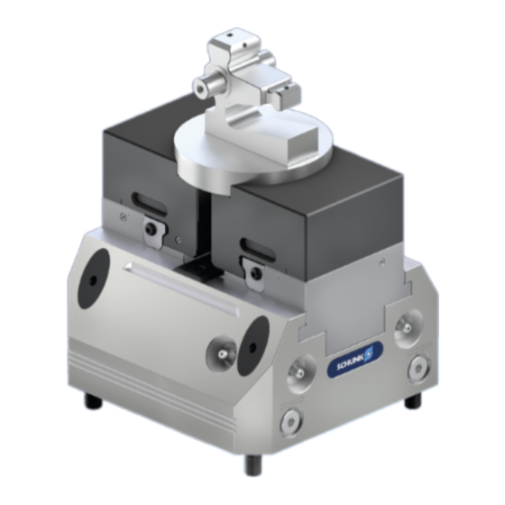
- Page 1 TANDEM Clamping Block KSP3-BWA, KSP3-LH-BWA Assembly and Operating Manual Translation of Original Operating Manual...
- Page 2 Imprint Imprint Copyright: This manual is protected by copyright. The author is SCHUNK GmbH & Co. KG. All rights reserved. Technical changes: We reserve the right to make alterations for the purpose of technical improvement. Document number: 1485610 Version: 01.00 | 08/03/2023 | en...
-
Page 3: Table Of Contents
Table of Contents Table of Contents 1 General ..................... 5 About this manual................1.1.1 Presentation of Warning Labels ............. 1.1.2 Applicable documents ..............1.1.3 Sizes..................1.2 Warranty ................... 1.3 Scope of delivery................. 1.4 Accessories ..................2 Basic safety notes ................2.1 Intended use.................. - Page 4 Table of Contents 5.4.2 Inserting clamping contour WTR-A ..........31 5.4.3 Quick-change jaws WTG-A ............33 5.4.4 Accessories for quick-change jaw WTG-A ......... 35 5.4.5 Gripper finger FIN WTR-A ............. 37 6 Function .................... 39 6.1 Functional description of quick-change jaw system........39 6.2 Manual jaw change ................
-
Page 5: General
General 1 General 1.1 About this manual This manual contains important information for a safe and appropriate use of the product. This manual is an integral part of the product and must be kept accessible for the personnel at all times. Before starting work, the personnel must have read and understood this operating manual. -
Page 6: Applicable Documents
SEI 6x reversible clamping inserts suitable for WTG-A STG clamping bars suitable for WTG-A Gripper finger FIN WTR-A for handling the changing jaws, suitable for SCHUNK universal grippers SCHUNK universal grippers 01.00 | KSP3-BWA, KSP3-LH-BWA | TANDEM Clamping Block | en | 1485610... -
Page 7: Basic Safety Notes
Structural changes should only be made with the written approval of SCHUNK. 01.00 | KSP3-BWA, KSP3-LH-BWA | TANDEM Clamping Block | en | 1485610... -
Page 8: Spare Parts
Use of unauthorized spare parts Using unauthorized spare parts can endanger personnel and damage the product or cause it to malfunction. Use only original spare parts or spares authorized by SCHUNK. 2.5 Use of special chuck jaws Requirements of the chuck jaws... -
Page 9: Personnel Qualification
Basic safety notes 2.7 Personnel qualification Inadequate qualifications of the personnel If the personnel working with the product is not sufficiently qualified, the result may be serious injuries and significant property damage. All work may only be performed by qualified personnel. Before working with the product, the personnel must have read and understood the complete assembly and operating manual. -
Page 10: Personal Protective Equipment
Basic safety notes 2.8 Personal protective equipment Use of personal protective equipment Personal protective equipment serves to protect staff against danger which may interfere with their health or safety at work. When working on and with the product, observe the occupational health and safety regulations and wear the required personal protective equipment. -
Page 11: Transport
Basic safety notes 2.10 Transport Handling during transport Incorrect handling during transport can make the product and its accessories unsafe and risks the danger of serious injuries and considerable material damage. When handling heavy weights, use lifting equipment to lift the product and transport it by appropriate means. -
Page 12: Fundamental Dangers
Basic safety notes 2.13 Fundamental dangers General Observe safety distances. Never deactivate safety installations. Before commissioning the product, take suitable protective measures to secure the danger zone. Provide a secured protective enclosure for automated use of the clamping device. Disconnect power sources before assembly, conversion, maintenance or adjustment work. -
Page 13: Protection Against Dangerous Movements
Basic safety notes 2.13.3 Protection against dangerous movements Unexpected movements Residual energy in the system may cause serious injuries while working with the product. Switch off the energy supply, ensure that no residual energy remains and secure against inadvertent reactivation. Never rely solely on the response of the monitoring function (dynamic pressure monitoring with pressure sensors) to avert danger. - Page 14 Basic safety notes WARNING Risk of injury from falling parts during transport, assembly and disassembly of the product and its accessories. Use suitable load handling equipment for transport Do not remain in the danger zone Wear protective equipment (protective shoes) WARNING Danger of crushing due to the chuck jaws approaching the workpiece during the clamping procedure when loading and...
-
Page 15: Technical Data
Technical data 3 Technical data Installation position Operating temperature +5 °C to +60 °C Noise emission [dB(A)] ≤ 70 Pressure medium Compressed air, compressed air quality according to ISO 8573-1:7 4 4 Max. speed of rotation for workpiece 100 RPM clamping Description KSP3-BWA Stroke per jaw [mm] Clamping force at max. - Page 16 Technical data KSP3-BWA / KSP3-LH-BWA Dimension Ø C 6H7 x 12 8H7 x 14 8H7 x 14 10H7 x 20 29.5 45.5 34.5 51.8 59.7 92.6 139.6 85.5 13.5 15.5 Ø Q 10f7 10f7 12f7 14f7 Ø R 18.7 58.5 46.8 67.8 77.8...
- Page 17 Technical data Optional Z variant ±0.01 mm positioning accuracy to clamping center Clamping sleeve ±0.04 mm positioning accuracy to clamping center Clamping sleeve fitting screw ±0.02 mm positioning accuracy to clamping center 01.00 | KSP3-BWA, KSP3-LH-BWA | TANDEM Clamping Block | en | 1485610...
-
Page 18: Tightening Torques For Screws
Tightening torques for screws 4 Tightening torques for screws Tightening torques for mounting the clamping system on the machine table (screw quality 10.9) Screw size M10 M12 M14 M16 M18 M20 M22 M24 Tightening torque 400 500 (Nm) Tightening torques for mounting clamping inserts or clamping bars on the changing jaws (screw quality 12.9) Screw size... -
Page 19: Assembly And Connection
Assembly and connection 5 Assembly and connection The specified item numbers for the corresponding individual components refer to the illustrations for assembly or connections of the clamping force block and to the "Assembly Drawings" chapter } 10 [/ 68] WARNING Danger of crushing due to the product approaching the machine table during assembly. -
Page 20: Mounting The Clamping Force Block On The Base Plate (If Both Parts Are Delivered Separately)
Assembly and connection NOTE For vertical installation, the opening of the coolant drain (V) must always face downwards Surface »X« is parallel to the guideway of the base jaws (2) in order to be able to align the clamping force block on the machine table or check the positioning. - Page 21 Assembly and connection NOTE: If the clamping force block and base plate are ordered separately, the screws, O-rings and clamping sleeves for assembling the parts are included in the accessory kit that comes with the clamping force block. Do not open the connections on the front of the clamping force block (I, II), or seal them with suitable dummy plugs (M5 or G1/8").
-
Page 22: Connecting The Clamping Block
Assembly and connection 5.3 Connecting the clamping block OPEN (front) CLOSED (front) OPEN (bottom) CLOSED (bottom) Coolant drainage / connection for air purge (front) Dynamic pressure monitoring for jaw end position "open" Dynamic pressure monitoring for system control of changing jaw no. 1 with simultaneous blow-out function Dynamic pressure monitoring for system control of changing jaw no. -
Page 23: Supply Lines
Assembly and connection 5.3.1 Supply lines The clamping force block has four air connections for supplying the clamping function: I, II, III, IV. Two connections for OPEN (I and III) and two connections for CLOSE (II and IV). The application determines whether the clamping force block for the clamping function is connected on the bottom side or on the front side. -
Page 24: Dynamic Pressure Monitoring Of The Jaw End Positions
Assembly and connection Requirements for compressed air supply: compressed air, compressed air quality according to ISO 8573-1:6 4 4. Unconditioned compressed air contains dust, oil particles and moisture, all of which can lead to malfunctions or premature wear in the clamping force block. The oiler should be no more than 2 meters from the coupling point. -
Page 25: Air Transfer In Quick-Change Jaw Wtr-A
Assembly and connection 5.3.4 Air transfer in quick-change jaw WTR-A Dynamic pressure monitoring for checking the flat work surface of the workpiece is integrated in the changing jaw set no. 1 via connection 8 on the bottom side. Work surface ①... - Page 26 Assembly and connection Description WTR-A 100 WTR-A 140 WTR-A 160 WTR-A 250 1479313 1479314 1479315 1479316 suitable for sizes KSP3 / (-LH) 100- KSP3 / (-LH) 140- KSP3 / (-LH) 160- KSP3 / (-LH) 250- 46.4 46.8 67.8 77.8 124.8 Ø...
-
Page 27: Pneumatic Circuit Diagram
Assembly and connection 5.3.5 Pneumatic circuit diagram Pneumatics symbols Actuation 5/3 directional control valve, center position ventilated 3/2 directional control valve Pressure switch Pressure gauge Flow control valve Compressed air supply ← → "Open" jaw stroke end position → ← "Closed"... -
Page 28: Quick-Change Jaws And Accessories
Assembly and connection 5.4 Quick-change jaws and accessories The TANDEM clamping force block can be equipped with suitable quick-change jaws. These are designed with mounts for the automated change procedure. They can also be changed manually. The system is only designed for O.D. workpiece clamping. -
Page 29: Quick-Change Jaws Wtr-A
Assembly and connection 5.4.1 Quick-change jaws WTR-A The quick-change jaws WTR-A correspond to a top jaw blank. The clamping contour can be individually adjusted. The jaw steps can be milled to a limited extent. The clamping contour must be placed under clamping pressure. Additionally, a spacer with sufficient clamping stroke reserve must be clamped between the changing jaws. - Page 30 Assembly and connection Description WTR-A 100 WTR-A 140 WTR-A 160 WTR-A 250 1479313 1479314 1479315 1479316 suitable for sizes KSP3 / (-LH) KSP3 / (-LH) KSP3 / (-LH) KSP3 / (-LH) 100-BWA 140-BWA 160-BWA 250-BWA 46.4 46.8 67.8 77.8 124.8 Individual 0.47 weight [kg]...
-
Page 31: Inserting Clamping Contour Wtr-A
Assembly and connection Stroke width TANDEM KSP3 100-BWA 1.6 … 3.6 3.2 … 7.2 KSP3 140-BWA 2 ... 5 4 ... 10 KSP3 160-BWA 2 ... 5 4 ... 10 KSP3 250-BWA 2 ... 7 4 ... 14 KSP3-LH 100-BWA 3.6 ... - Page 32 Assembly and connection Preparing to machine the workpiece clamping contour Move the clamping force block to the open position Insert changing jaws into the change interfaces according to set numbers 1 and 2 Place spacer is clamping position. Height of spacer close to workpiece clamping height. Clamp the spacer Select actuating pressure identical to later workpiece machining Machine the clamping contour with recessed steps under clamping pressure...
-
Page 33: Quick-Change Jaws Wtg-A
Assembly and connection 5.4.3 Quick-change jaws WTG-A The quick-change jaw WTG-A is a version for clamping raw parts. Suitable accessories for adapting the workpiece clamping can be attached via grid holes. Hardened, with bore hole grid as supporting jaw for SEI 6x reversible clamping inserts and STG type clamping bars. - Page 34 Assembly and connection Description WTG-A 100 WTG-A 140 WTG-A 160 WTG-A 250 1479317 1479318 1479319 1479320 suitable for sizes KSP3 / (-LH) KSP / (-LH) KSP3 / (-LH) KSP / (-LH) 100-BWA 140-BWA 160-BWA 250-BWA 46.4 46.8 67.8 77.8 124.8 16.5 16.5 Ø...
-
Page 35: Accessories For Quick-Change Jaw Wtg-A
Assembly and connection 5.4.4 Accessories for quick-change jaw WTG-A SEI 6x reversible clamping inserts STG clamping bars NOTE: 6x reversible clamping inserts and clamping bars come with mounting screws. Only use the mounting screws included at the specified torque when assembling } 4 [/ 18]. - Page 36 Assembly and connection Designation SEI 100-M6 SEI 160-M8 SEI 250-M10 0402317 0402318 0402319 suitable for quick-change jaws WTG-A 100 WTG- A 140 WTG-A 250 WTG-A 160 Ø D Designation STG 100 STG 140 STG 160 STG 250 0402314 1452063 0402315 0402316 suitable for quick-change jaws WTG-A 100...
-
Page 37: Gripper Finger Fin Wtr-A
For the automated handling of the WTR-A and WTG-A quick- change jaws, gripper fingers with spring-loaded mounting pieces are provided. These are designed for SCHUNK parallel grippers. They are attached with additional sleeves, which are enclosed with the parallel gripper. The gripper fingers are symmetrically oriented and engage in the mount recesses of the changing jaws on both sides. - Page 38 Assembly and connection Description FIN WTR-A 100 FIN WTR-A 140 FIN WTR-A 160 FIN WTR-A 250 11485599 1485600 1485601 1485602 suitable for sizes WTR-A 100 WTR-A 140 WTR-A 160 WTR-A 250 suitable for PGN-plus 80-1 PGN-plus 100-1 PGN-plus 100-1 PGN-plus 125-1 parallel grippers PGN-plus-P 80-1 PGN-plus-P...
-
Page 39: Function
Change interface of quick-change jaw WTR-A (illustration with clamping contour) Gripper finger 2-finger universal gripper SCHUNK PGN-plus-P Changing mounts on both sides with mold contour WTG-A (illustration with clamping contour) 01.00 | KSP3-BWA, KSP3-LH-BWA | TANDEM Clamping Block | en | 1485610... - Page 40 (B). The changing jaws (D) can be changed automatically, in conjunction with FIN WTR-A gripper fingers (E) using a SCHUNK universal gripper (F) or manually. The change procedure for the changing jaws involves pushing them in or out from the center of the clamping device into the change interfaces.
-
Page 41: Manual Jaw Change
Function 6.2 Manual jaw change TANDEM in open position ready for the change procedure Position the changing jaw centrally lengthwise and crosswise over the centering insert Press the changing jaw down towards the flat surface, the spring bolts in the centering insert are pressed into the change interface from the inside to the outside with sufficient contact force. -
Page 42: Automated Jaw Change With Quick-Change Jaws
Function 6.3 Automated jaw change with quick-change jaws Automated jaw change with WTR-A Inserting the changing jaw into the change interface TANDEM in open position ready for change procedure. Changing jaw is picked up with gripper fingers, note the jaw number. Position the changing jaw centrally over the base jaw (laterally adjusted flush with applied angle). - Page 43 Function Removing the changing jaw from the change interface TANDEM in open position ready for the change procedure Changing jaw is picked up with gripper fingers Push out the changing jaw from the outside to the inside using sufficient contact force against the spring lock to push it out of the change interface.
-
Page 44: Function Sequence For Automation With Quick-Change Jaws
Function 6.3.1 Function sequence for automation with quick-change jaws The KSP3-BWA is equipped with monitoring functions for automation during jaw changes. These can be actuated individually and integrated into a program sequence. The operating states are checked with a differential pressure switch. A malfunction when loading or unloading the changing jaw or the workpiece interrupts the program sequence and protects the robot handling and the TANDEM components from damage. - Page 45 Function Actuate KSP3-BWA in position OPEN →Monitor stroke end positions via connection 1 (A1) and connection 4 (A4) (2 bar) Pick up changing jaw (jaw number 1) with gripper handling Activate dynamic pressure monitoring for system control of changing jaw number 1 at connection 2 (A2) (2 bar) Insert the changing jaw into the change interface 1 Open and lift off gripper →...
-
Page 46: Operating Conditions
Function 6.4 Operating conditions When changing the jaws, make sure that the changing jaws are securely locked to the clamping force block. If changing jaws are joined, workpiece clamping must also be carried out. If clamping force blocks are in the machining area or, for example, in a tombstone where no workpiece clamping takes place, the changing jaws must be removed. - Page 47 Function Horizontal positioning for changing and exchanging the changing jaws is preferable Setting down and lifting in horizontal clamping device orientation Change procedure in vertical installation situation Ensure that the changing jaw is completely locked before lifting off the gripper In automated operation and during swiveling movements when using a multi- equipped clamping device with clamping force blocks, always provide for workpiece clamping.
-
Page 48: Trouble Shooting
Place the oiler closer to the clamping system, adjust the necessary oil quantity. Chuck piston screw broken (overload) Send clamping system to SCHUNK for repairs or disassemble clamping system and repair using original SCHUNK spare parts. } 8.4.2 [/ 58] Piston rod or piston rod screw... - Page 49 Trouble shooting Clamping force getting weaker Possible cause Solution(s) Clamping force block not sealed tightly Check connection and seal screws; reseal or replace. Seals damaged Disassemble clamping force block } 8.4.2 [/ 58] and replace all the seals (see sealing kit lists } 9 [/ 64]) Inadequate lubrication...
- Page 50 Trouble shooting Monitoring functions of the stroke end positions do not work properly Possible cause Solution(s) Monitoring pieces in the base jaws not Readjust monitoring piece for the required positioned exactly function. Compressed air leakage because the Readjust monitoring piece for the required monitoring piece is pressed too lightly function.
-
Page 51: Maintenance And Care
Maintenance and care 8 Maintenance and care 8.1 Notes Original spare parts Only use original spare parts from SCHUNK when replacing wearing parts/spare parts. Replacing the housing and base jaws The base jaws and the guides in the housing are matched to each other. -
Page 52: Maintenance Work
Maintenance and care 8.4 Maintenance work 8.4.1 Lubrication CAUTION Allergic reactions or irritation due to skin or eye contact with lubricants on the product Wear protective equipment (protective gloves, protective goggles) in case of foreseeable contact with lubricants on the product (e.g. -
Page 53: Basic Cleaning, Disassembly And Reassembly
Maintenance and care Central lubrication To use central lubrication, the set- screws of the factory sealed connections (6, 7) must be removed. For proper lubrication, both supply lines must be connected. The central lubrication system must be suitable for greases of NLGI 2 classification. - Page 54 Maintenance and care Disassembly Before disassembling the machine, switch it off and secure it against being switched on again. Then remove all compressed air lines. No residual energy may be left in the clamping device. Pull out plug (81) with installed O-ring (83). Unscrew the screws (84) and the fitting screws (82) and disassemble the clamping system from the machine table.
- Page 55 Maintenance and care Variant with clamping force maintenance (AS) Fasten mounting cover (200) with cheese-head screws DIN EN ISO 4762} 8.6 [/ 62]. for size 100: M5 x 8 - 14 for size 140: M5 x 12 - 16 for size 160: M5 x 16 - 20 for size 250: M6 x 20 - 25 Variant without clamping force maintenance Unscrew the screw (69) by holding it against the...
- Page 56 Maintenance and care Variant with clamping force maintenance (AS) Warning! Risk of injury due to spring forces! The cylinder piston and cover are under spring tension! Clamp the product between the base jaws (2) and the mounting cover (200) using a suitable device (e.g. press, vise) so that the screws in the cover can still be removed.
- Page 57 Maintenance and care Maintenance Clean all parts thoroughly and check for damage and wear. Treat all greasing areas with lubricant } 8.3 [/ 51]. Replace all wearing parts and seals if necessary [/ 64]. } 9 Assembly Assembly is done in the reverse order of disassembly. In doing so, observe the following.
-
Page 58: Adjusting The Pneumatic Jaw End Position Monitoring
Maintenance and care 8.4.3 Adjusting the pneumatic jaw end position monitoring * Depending on the size, access provided to the pneumatic jaw end position monitoring ** Disassembly for sizes 100, 140, 160 *** Disassembly for size 250 Access to the pneumatic jaw end position monitoring is below the centering insert (15) for each base jaw (2) for sizes 100, 140 and 160. -
Page 59: Leak Test
Maintenance and care Base jaw 2: monitoring closed jaw position Move base jaws to CLOSED position Remove set-screws (63) Screw the set-screw (61) into the bore hole with the marking "oo" up to the stop and then unscrew it again by a few turns. Slowly screw the set-screw (61) into the bore hole with the marking "o"... -
Page 60: Control Of Proper Function
Only use original SCHUNK spare parts when replacing damaged items. If the robot handling unit is involved in a collision with the... -
Page 61: Functional Test Of The Monitoring For The Jaw Stroke Position
Maintenance and care 8.5.2 Functional test of the monitoring for the jaw stroke position The following components are required for the test: volume flow controller, pressure sensor. Check the jaw stroke position in OPEN position → dynamic pressure in "open" state at base jaw 1, (connection no. 1) After a traverse path of the base jaws, a pressure difference of 1 bar is required →... -
Page 62: Assembly Device For Version -As
Maintenance and care 8.6 Assembly device for version -AS Dimension Sizes Ø d1 97.5 137.5 155.5 Ø d2 Ø d3 Ø d4 Ø d5 10.5 38.9 45.5 93.8 38.9 49.5 93.8 43.5 63.5 19.4 60.5 68.3 19.4 68.3 34.3 45.5 93.8 26.8 60.5... -
Page 63: Storage Rack Of The Quick-Change Jaws In Automation Mode
Maintenance and care 8.7 Storage rack of the quick-change jaws in automation mode The quick-change jaws can be hung in an inlay on the clamping chamfer. This protects and houses the changing jaw. It should be designed to stand at an angle to ensure a secure hold. The design of the recess in a steel plate is shown below for size 160. -
Page 64: Sealing Kit Lists, Accessory Kits And Parts Lists
Sealing kit lists, accessory kits and parts lists 9 Sealing kit lists, accessory kits and parts lists When ordering spare parts, the type, size and, if possible, the serial number of the clamping force block must always be stated to avoid delivery mistakes. Seals, sealing elements, fittings, springs, bearings, screws, wiper bars and parts that come into contact with the workpiece are not covered by the warranty. -
Page 65: Accessory Packs
Sealing kit lists, accessory kits and parts lists 9.2 Accessory packs Accessory kit * Size 100 1441626 Size 140 1441628 Size 160 1441629 Size 250 1441630 * For included items, see note Z in the Parts List chapter below. 9.3 Parts lists 9.3.1 TANDEM Clamping Block Parts list "Standard stroke"... - Page 66 Sealing kit lists, accessory kits and parts lists Item Description Quantity Note Combined sealing ring O-ring O-ring O-ring 250 / V Flat gasket Set-screw Set-screw Set-screw Set-screw Countersunk screw Countersunk screw Countersunk screw Screw Screw Countersunk screw Screw 140 / 160 Screw Screw Set-screw...
-
Page 67: Quick-Change Jaw Wtr-A
Sealing kit lists, accessory kits and parts lists 9.3.2 Quick-change jaw WTR-A Item Description Quantity Changing jaw Set-screw Accessory kit (set-screws) 9.3.3 Gripper finger FIN WTR-A Item Description Quantity Top jaw Mounting piece 3 / * Compression spring 2 / *4 Pan-head screw 5 / * Screw... -
Page 68: Assembly Drawings
Assembly drawings 10 Assembly drawings 10.1 TANDEM KSP3-BWA for variant "-AS" Centering with fitting screws Centering with clamping sleeves Centering with cylindrical pins (Z variant) for transport (size 250) Locking screw with O-ring (size 250) Wiper set = 2 x item 17 + 2 x item 18 01.00 | KSP3-BWA, KSP3-LH-BWA | TANDEM Clamping Block | en | 1485610... -
Page 69: Quick-Change Jaw Wtr-A
Assembly drawings 10.2 Quick-change jaw WTR-A contained in accessory kit 10.3 Gripper finger FIN WTR-A Sleeves included with SCHUNK universal for sizes 140, 160 gripper 01.00 | KSP3-BWA, KSP3-LH-BWA | TANDEM Clamping Block | en | 1485610... -
Page 70: Translation Of The Original Declaration Of Incorporation
Directive 2006/42/EG, Annex II, Part 1.B of the European Parliament and of the Council on machinery. Hersteller/ H.-D. SCHUNK GmbH & Co. Spanntechnik KG Inverkehrbringer Lothringer Str. 23 D-88512 Mengen We hereby declare that on the date of the declaration the following partly completed machine complied with all basic safety and health regulations found in the directive 2006/42/EC of the European Parliament and of the Council on machinery. -
Page 71: Appendix On Declaration Of Incorporation, As Per 2006/42/Ec, Annex Ii, No. 1 B
Appendix on Declaration of Incorporation, as per 2006/42/EC, annex II, No. 1 B 12 Appendix on Declaration of Incorporation, as per 2006/42/EC, annex II, No. 1 B 1. Description of the basic safety and health protection requirements, as per 2006/42/EC, Annex I, that apply to and are fulfilled for the scope of the incomplete machine: Product designation TANDEM clamping force block pneumatic (jaw quick-change for automation) - Page 72 Appendix on Declaration of Incorporation, as per 2006/42/EC, annex II, No. 1 B Control Systems 1.2.4.4 Assembly of machinery 1.2.5 Selection of control or operating modes 1.2.6 Failure of the power supply Protection against mechanical hazards 1.3.1 Risk of loss of stability 1.3.2 Risk of break-up during operation 1.3.3...
- Page 73 Appendix on Declaration of Incorporation, as per 2006/42/EC, annex II, No. 1 B Risks due to other hazards 1.5.13 Emissions of hazardous materials and substances 1.5.14 Risk of being trapped in a machine 1.5.15 Risk of slipping, tripping or falling 1.5.16 Lightning Maintenance...
- Page 74 01.00 | KSP3-BWA, KSP3-LH-BWA | TANDEM Clamping Block | | 1485610...
- Page 75 01.00 | KSP3-BWA, KSP3-LH-BWA | TANDEM Clamping Block | | 1485610...
- Page 76 H.-D. SCHUNK GmbH & Co. Spanntechnik KG Lothringer Str. 23 D-88512 Mengen Tel. +49-7572-7614-0 Fax +49-7572-7614-1099 info@de.schunk.com schunk.com Folgen Sie uns I Follow us Wir drucken nachhaltig I We print sustainable...
Need help?
Do you have a question about the TANDEM KSP3-BWA 100 and is the answer not in the manual?
Questions and answers