SCHUNK TANDEM KSP3 Assembly And Operating Manual
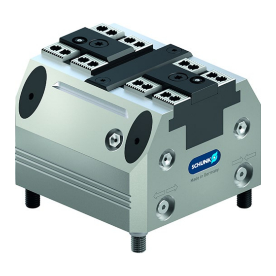
Clamping force block
Hide thumbs
Also See for TANDEM KSP3:
- Assembly and operating manual (52 pages) ,
- Assembly and operating manual (52 pages) ,
- Assembly and operating manual (44 pages)

Related Manuals for SCHUNK TANDEM KSP3


Summary of Contents for SCHUNK TANDEM KSP3
- Page 1 Translation of the Original Operating Manual TANDEM Clamping Force Block KSP3, KSP3-LH, KSP3-F Assembly and Operating Manual Superior Clamping and Gripping...
- Page 2 Imprint Imprint Copyright: This manual is protected by copyright. The author is SCHUNK GmbH & Co. KG. All rights reserved. Technical changes: We reserve the right to make alterations for the purpose of technical improvement. Document number: 1463318 Version: 01.00 |08/04/2021|en...
-
Page 3: Table Of Contents
5.3.1 Supply lines ....................26 5.3.2 Dynamic pressure monitoring of the jaw end positions (variant "PM") ..27 5.3.3 Air coupling in top jaw (variant "PM") ............28 5.3.4 Pneumatic circuit diagram ................30 6 Troubleshooting ...................... 31 01.00|1463318 Tandem KSP3, KSP3-LH, KSP3-F |en... - Page 4 9.1 KSP3, KSP3-LH ......................50 9.2 KSP3-F ........................51 10 Translation of the original declaration of incorporation ........... 53 11 Appendix on Declaration of Incorporation, as per 2006/42/EC, annex II, No. 1 B ..54 01.00|1463318 Tandem KSP3, KSP3-LH, KSP3-F |en...
-
Page 5: General
Non-observance will inevitably cause irreversible injury or death. WARNING Dangers for persons! Non-observance can lead to irreversible injury and even death. CAUTION Dangers for persons! Non-observance can cause minor injuries. CAUTION Material damage! Information about avoiding material damage. 01.00|1463318 Tandem KSP3, KSP3-LH, KSP3-F |en... -
Page 6: Applicable Documents
* A cycle consists of a complete clamping process ("Open" and "Close"). Scope of Delivery Clamping force block KSP3 or KSP3-LH or KSP3-F (without top jaws) ACCESSORY KIT: (for contents, see sealing kit list and parts list) ( 8.1, Page 44) 01.00|1463318 Tandem KSP3, KSP3-LH, KSP3-F |en... -
Page 7: Basic Safety Notes
(for example, to machine clamped workpieces) without additional protective equipment. • The technical data specified by the manufacturer are exceeded during usage. • It is used with machines/systems or workpieces that are not designed to be used with it. 01.00|1463318 Tandem KSP3, KSP3-LH, KSP3-F |en... -
Page 8: Constructional Changes
Use of unauthorized spare parts Using unauthorized spare parts can endanger personnel and damage the product or cause it to malfunction. • Use only original spare parts or spares authorized by SCHUNK. Use of special chuck jaws Requirements of the chuck jaws When using special chuck jaws, please observe the following rules: •... -
Page 9: Environmental And Operating Conditions
Qualified personnel Due to its technical training, knowledge and experience, qualified personnel is able to perform the delegated tasks, recognize and avoid possible dangers and knows the relevant standards and regulations. 01.00|1463318 Tandem KSP3, KSP3-LH, KSP3-F |en... -
Page 10: Personal Protective Equipment
• Avoid any manner of working that may interfere with the function and operational safety of the product. • Use the product as intended. • Observe the safety notes and assembly instructions. 01.00|1463318 Tandem KSP3, KSP3-LH, KSP3-F |en... -
Page 11: Transport
• Order appropriately trained personnel to rectify the malfunction. • Do not recommission the product until the malfunction has been rectified. • Test the product after a malfunction to establish whether it still functions properly and no increased risks have arisen. 01.00|1463318 Tandem KSP3, KSP3-LH, KSP3-F |en... -
Page 12: Disposal
Falling loads may cause serious injuries and even death. • Stand clear of suspended loads and do not step into their swiveling range. • Never move loads without supervision. • Do not leave suspended loads unattended. 01.00|1463318 Tandem KSP3, KSP3-LH, KSP3-F |en... -
Page 13: Protection During Commissioning And Operation
Before starting up the machine or automated system, check that the EMERGENCY STOP system is working. Prevent operation of the machine if this protective equipment does not function correctly. 01.00|1463318 Tandem KSP3, KSP3-LH, KSP3-F |en... -
Page 14: Notes On Particular Risks
Danger of crushing due to the chuck jaws approaching the workpiece during the clamping procedure when loading and unloading manually. • Prioritize automated loading • Do not reach between the workpiece and the chuck jaw during the clamping procedure 01.00|1463318 Tandem KSP3, KSP3-LH, KSP3-F |en... - Page 15 Allergic reactions or irritation due to skin or eye contact with lubricants on the product. • In case of foreseeable contact with lubricants on the product (e.g. when lubricating or cleaning), wear protective equipment (protective gloves, protective goggles) 01.00|1463318 Tandem KSP3, KSP3-LH, KSP3-F |en...
-
Page 16: Technical Data
[kN] 18.5 max. pressure standard/ 9***/ 9***/ AS variant [bar] 9*** 9*** min. opening pressure AS variant [bar] Repeat accuracy** [mm] 0.01 0.01 0.01 0.01 0.02 max. jaw height [mm] Weight [kg] 01.00|1463318 Tandem KSP3, KSP3-LH, KSP3-F |en... - Page 17 Clamping force is the arithmetic sum of the individual forces occurring at the chuck jaws at distance "H" (see also catalog). End position spread after 100 consecutive strokes. When using an ABP-A base plate, the maximum pressure must be limited to 7 bar 01.00|1463318 Tandem KSP3, KSP3-LH, KSP3-F |en...
- Page 18 8H7 x 14 8H7 x 14 10H7 x 20 29.5 45.5 34.5 51.8 59.7 92.6 33.6 139.6 50.7 69.2 72.7 82.2 98.2 13.5 15.5 Ø Q 10f7 10f7 12f7 14f7 Ø R 18.7 58.5 26.5 01.00|1463318 Tandem KSP3, KSP3-LH, KSP3-F |en...
- Page 19 Technical data Optional Z variant ±0.01 mm to clamping center Clamping sleeve ±0.04 mm to clamping center Clamping sleeve fitting screw ±0.02 mm to clamping center Only with variant "PM" 01.00|1463318 Tandem KSP3, KSP3-LH, KSP3-F |en...
-
Page 20: Tightening Torques For Screws
Designation Screw size KSP3 / KSP3-LH Tightening torque M (Nm) KSP3-F Tightening torque M (Nm) Tightening torques for mounting the cover on the body (screw quality A2-70) Size Screw size Tightening torque M (Nm) 01.00|1463318 Tandem KSP3, KSP3-LH, KSP3-F |en... -
Page 21: Assembly And Connection
Assembly of the Clamping Block on the machine table Cylindrical pins Ø m6( 8.3, Page 49) Fitting screw Ø f7 (( 8.3, Page 49)) Screw DIN EN ISO 4762 Clamping sleeve DIN EN ISO 13337 01.00|1463318 Tandem KSP3, KSP3-LH, KSP3-F |en... - Page 22 (item 84). The two cylindrical pins (item 34) are used for alignment with repeat accuracy. Do not realign the clamping force block after removing it from the machine table (e.g., after replacing the seals). 01.00|1463318 Tandem KSP3, KSP3-LH, KSP3-F |en...
-
Page 23: Mounting The Clamping Block On The Base Plate
TANDEM clamping force blocks. The function for monitoring the jaw position can only be connected externally. When joining, make sure the air feed- throughs for the clamping system and the base plate are precisely aligned. 01.00|1463318 Tandem KSP3, KSP3-LH, KSP3-F |en... - Page 24 The oiler should be no more than 2 meters from the coupling point. The clamping force block has two more base connections (6/7) for direct lubrication through the machine table. These connections come sealed on delivery with set-screws (item 62). 01.00|1463318 Tandem KSP3, KSP3-LH, KSP3-F |en...
-
Page 25: Connecting The Clamping Force Block
Dynamic pressure monitoring for jaw end position "closed" Bottom connection for coolant drain or use for air purge Bottom connection for lubrication (one-sided supply, left) Bottom connection for lubrication (one-sided supply, right) No use for connection 1-7 with size 64 01.00|1463318 Tandem KSP3, KSP3-LH, KSP3-F |en... -
Page 26: Supply Lines
The oiler should be no more than 2 meters from the coupling point. The clamping force block has two more base connections (6/7) for direct lubrication through the machine table. These connections come sealed on delivery with set-screws (item 62). 01.00|1463318 Tandem KSP3, KSP3-LH, KSP3-F |en... -
Page 27: Dynamic Pressure Monitoring Of The Jaw End Positions (Variant "Pm")
Connection 1 → monitoring open jaw position. Connection 4 → monitoring closed jaw position. The max. pressure for the monitoring functions is 2 bar. Limit volumetric flow to 10 l/min. Pressure difference between stroke end positions min. 1 bar. 01.00|1463318 Tandem KSP3, KSP3-LH, KSP3-F |en... -
Page 28: Air Coupling In Top Jaw (Variant "Pm")
2 +0.1 2 +0.1 2 +0.1 2 +0.1 2.5 +0.1 Non-tolerated dimensions according to DIN ISO 2768mH. When using top jaws type STR / STR-H / STR-S, it is essential to observe dimension E. 01.00|1463318 Tandem KSP3, KSP3-LH, KSP3-F |en... - Page 29 In doing so, the transfer dimensions ØC, D, E and F must be observed. Max. pressure 2 bar. Limit volumetric flow to 10 l/min 01.00|1463318 Tandem KSP3, KSP3-LH, KSP3-F |en...
-
Page 30: Pneumatic Circuit Diagram
→ ← Jaw stroke "close" Dynamic pressure monitoring for jaw end position "open" (2 bar) Air coupling in top jaw 1 Air coupling in top jaw 2 Dynamic pressure monitoring jaw stroke "closed" (2 bar) 01.00|1463318 Tandem KSP3, KSP3-LH, KSP3-F |en... -
Page 31: Troubleshooting
Check maintenance unit, perform maintenance work. Place the oiler closer to the clamping system; adjust the necessary oil quantity Chuck piston screw broken (overload) Send clamping system to SCHUNK for repairs or disassemble clamping system and repair using original SCHUNK spare parts... - Page 32 ( 7, Page 33) Pressure change due to clamping Adjust clamping stroke to the workpiece to >0.3 stroke too low mm/jaw Seals damaged Replace seals in cover and adapter plate ( 8.1, Page 44) 01.00|1463318 Tandem KSP3, KSP3-LH, KSP3-F |en...
-
Page 33: Maintenance And Care
Replacement of the housing and base jaws The base jaws and the guides in the housing are matched to each other. To replace these parts, send the entire product to SCHUNK with a repair order. Maintenance variant with clamping force maintenance (AS) The cylinder piston must be disassembled or assembled using a disassembly and assembly device. -
Page 34: Greasing Areas / Lubricants
LINOMAX plus can also be used as an alternative to LINOMAX 200. However, the specified clamping forces exclusively refer to the LINOMAX 200 used by SCHUNK. When using LINOMAX plus, the clamping forces can be lower. 01.00|1463318 Tandem KSP3, KSP3-LH, KSP3-F |en... -
Page 35: Maintenance Work
• Only lubricate in the open position. • After greasing, run through the complete stroke several times. • Grease to be used and lubrication intervals. ( 7.3, Page 34) Size Grease quantity (strokes per grease nipple) 01.00|1463318 Tandem KSP3, KSP3-LH, KSP3-F |en... - Page 36 • Only lubricate in the open position. • After greasing, run through the complete stroke several times. • Grease to be used and lubrication intervals, ( 7.3, Page 34) Size Grease quantity (per connection) [cm³] 01.00|1463318 Tandem KSP3, KSP3-LH, KSP3-F |en...
-
Page 37: Basic Cleaning
• Pull out the plug (81). • Unscrew the screws (84) and the fitting screws (82) and disassemble the clamping system from the machine table. • If using adapter sleeves (85), remove them from the housing. 01.00|1463318 Tandem KSP3, KSP3-LH, KSP3-F |en... - Page 38 64: M3 x 12 for size 100: M5 x 8 -14 for size 140: M5 x 12 - 16 for size 160: M5 x 16 - 20 for size 250: M6 x 20 - 25 01.00|1463318 Tandem KSP3, KSP3-LH, KSP3-F |en...
- Page 39 (41) from the housing. Variant with clamping force maintenance (AS) Unscrew the screw (69) by holding it against the cylinder piston (4). Then pull the chuck piston (3) out of the housing via its extraction thread. 01.00|1463318 Tandem KSP3, KSP3-LH, KSP3-F |en...
- Page 40 Variant "PM" also includes O-ring (44), monitoring piece (7) and compression springs (26). Caution! The monitoring piece is under spring pre-load and is installed directionally oriented for each base jaw! See detail views for jaw 1 and jaw 2! 01.00|1463318 Tandem KSP3, KSP3-LH, KSP3-F |en...
- Page 41 • Slowly screw the set-screw (61) into the bore hole oo until the differential pressure sensor emits a switching signal. • Hand-tighten set-screw (61) in bore hole o. • Screw set-screw (63) in both bore holes and hand-tighten. 01.00|1463318 Tandem KSP3, KSP3-LH, KSP3-F |en...
-
Page 42: Leak Test
If the clamping system is leaking, check the screws first (e.g., with Metaflux leak detection spray). Seal any leaking screws. Once the fittings are sealed, check for leaks and replace if necessary (see Disassembling and Assembling the Clamping Force Block ).( 7.4.2, Page 42) 01.00|1463318 Tandem KSP3, KSP3-LH, KSP3-F |en... -
Page 43: Assembly Device
60.5 97.5 137.5 155.5 Ød2 Ød3 Ød4 Ød5 10.5 11.8 38.9 45.5 93.8 11.8 38.9 49.8 93.8 43.5 63.5 24.5 19.4 60.5 68.3 24.5 19.4 68.3 11.8 34.3 45.5 93.8 24.5 26.8 60.5 68.3 01.00|1463318 Tandem KSP3, KSP3-LH, KSP3-F |en... -
Page 44: Sealing Kits, Accessory Kits And Parts Lists
* For included items, see column > y < in the Parts List chapter below. Wearing parts - replacement when maintenance is performed is recommended The sealing kit can only be ordered as a compete kit. 01.00|1463318 Tandem KSP3, KSP3-LH, KSP3-F |en... -
Page 45: Monitoring Sealing Kit / Connection
Accessory kit ** ID number Size 64 1432277 Size 100 1428583 Size 140 1428599 Size 160 1428591 Size 250 1428597 ** For included items, see column > z < in the Parts List chapter below. 01.00|1463318 Tandem KSP3, KSP3-LH, KSP3-F |en... -
Page 46: Parts Lists
● ■ O-ring ☐ DIN ISO 3601 ● ● ● ● ■ O-ring ☐ ● DIN ISO 3601 O-ring ☐ ● DIN ISO 3601 O-ring ● ■ DIN ISO 3601 Set-screw ● Set-screw ● 01.00|1463318 Tandem KSP3, KSP3-LH, KSP3-F |en... - Page 47 ● Set-screw ● ● T-handle ● ● Parts list "fixed jaw" variant Item Designation Quantity Body >Housing< ● Base jaw ● Chuck piston ● Cylinder piston ● Cover ● Guide strip ● ● ● 01.00|1463318 Tandem KSP3, KSP3-LH, KSP3-F |en...
- Page 48 ■ O-ring ☐ ● DIN ISO 3601 O-ring ☐ ● DIN ISO 3601 O-ring ● ■ DIN ISO 3601 Set-screw ● Set-screw ● ● Set-screw ● ● ● ● Set-screw ● Countersunk screw ● 01.00|1463318 Tandem KSP3, KSP3-LH, KSP3-F |en...
- Page 49 = for size 140 e = for size 160 z = included in accessory kit f = for size 250 * Individual components are specially tuned to one another and cannot be replaced by the customer. 01.00|1463318 Tandem KSP3, KSP3-LH, KSP3-F |en...
-
Page 50: Assembly Drawings
Assembly drawings Assembly drawings KSP3, KSP3-LH 01.00|1463318 Tandem KSP3, KSP3-LH, KSP3-F |en... -
Page 51: Ksp3-F
Assembly drawings with variant "PM" with variant "AS" Centering with fitting screws D Centering with clamping sleeves Centering with cylindrical pins (Z variant) KSP3-F 01.00|1463318 Tandem KSP3, KSP3-LH, KSP3-F |en... - Page 52 Assembly drawings with variant "PM" with variant "AS" Centering with fitting screws D Centering with clamping sleeves Centering with cylindrical pins (Z variant) 01.00|1463318 Tandem KSP3, KSP3-LH, KSP3-F |en...
-
Page 53: Translation Of The Original Declaration Of Incorporation
Directive 2006/42/EG, Annex II, Part 1.B of the European Parliament and of the Council on machinery. Manufacturer/ H.-D. SCHUNK GmbH & Co. Spanntechnik KG Distributor Lothringer Str. 23 D-88512 Mengen We hereby declare that on the date of the declaration the following partly completed machine complied with all basic safety and health regulations found in the directive 2006/42/EC of the European Parliament and of the Council on machinery. -
Page 54: Appendix On Declaration Of Incorporation, As Per 2006/42/Ec, Annex Ii, No. 1 B
1.3.8.1 Moving transmission parts 1.3.8.2 Moving parts involved in the process 1.3.9 Risks of uncontrolled movements Required characteristics of guards and protective devices 1.4.1 General requirements 1.4.2 Special requirements for guards 1.4.2.1 Fixed guards 01.00|1463318 Tandem KSP3, KSP3-LH, KSP3-F |en... - Page 55 Supplementary essential health and safety requirements to offset hazards due to lifting operations Supplementary essential health and safety requirements for machinery intended for underground work Supplementary essential health and safety requirements for machinery presenting particular hazards due to the lifting of persons 01.00|1463318 Tandem KSP3, KSP3-LH, KSP3-F |en...
Need help?
Do you have a question about the TANDEM KSP3 and is the answer not in the manual?
Questions and answers