SCHUNK TANDEM KSH3 Assembly And Operating Manual
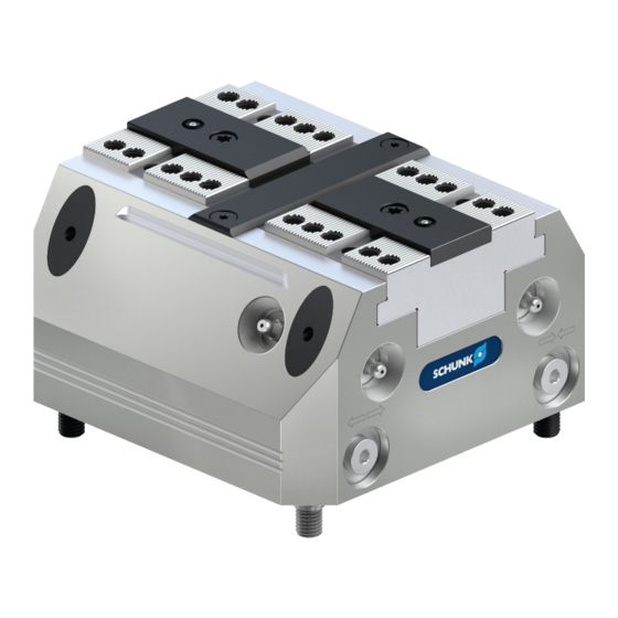
Clamping force block
Hide thumbs
Also See for TANDEM KSH3:
- Assembly and operating manual (52 pages) ,
- Translation of original operating manual (48 pages)

Related Manuals for SCHUNK TANDEM KSH3


Summary of Contents for SCHUNK TANDEM KSH3
- Page 1 Translation of the Original Operating Manual TANDEM Clamping Force Block KSH3, KSH3-LH, KSH3-F Assembly and Operating Manual Superior Clamping and Gripping...
- Page 2 Imprint Imprint Copyright: This manual is protected by copyright. The author is SCHUNK GmbH & Co. KG. All rights reserved. Technical changes: We reserve the right to make alterations for the purpose of technical improvement. Document number: 1477683 Version: 01.00 |29/06/2021|en...
-
Page 3: Table Of Contents
Table of contents Table of contents 1 General ........................5 1.1 About this manual ....................5 1.1.1 Presentation of Warning Labels ..............5 1.1.2 Applicable documents ................... 6 1.1.3 Sizes ....................... 6 1.2 Warranty ........................6 1.3 Scope of Delivery ...................... 6 2 Basic safety notes .................... - Page 4 Table of contents 7 Maintenance and care ..................... 28 7.1 Notes........................28 7.2 Maintenance and lubrication intervals ..............28 7.3 Greasing areas / lubricants ..................28 7.4 Maintenance work ....................29 7.4.1 Lubricate ...................... 29 7.4.2 Basic cleaning ....................30 7.4.3 Testing the leakage and tightness of the hydraulic system ......
-
Page 5: General
General General About this manual This manual contains important information for a safe and appropriate use of the product. This manual is an integral part of the product and must be kept accessible for the personnel at all times. Before starting work, the personnel must have read and understood this operating manual. -
Page 6: Applicable Documents
Applicable documents • General terms of business * • Catalog data sheet of the purchased product * The documents marked with an asterisk (*) can be downloaded on our homepage schunk.com 1.1.3 Sizes This operating manual applies to the following sizes: •... -
Page 7: Basic Safety Notes
Basic safety notes Basic safety notes Intended use • This product is intended for clamping and holding workpieces on machine tools and other suitable technical devices. • It is designed to be set up on a machine table or machine pallets. -
Page 8: Constructional Changes
Use of unauthorized spare parts Using unauthorized spare parts can endanger personnel and damage the product or cause it to malfunction. • Use only original spare parts or spares authorized by SCHUNK. Use of special chuck jaws Requirements of the chuck jaws When using special chuck jaws, please observe the following rules: •... -
Page 9: Environmental And Operating Conditions
Basic safety notes Environmental and operating conditions Required ambient conditions and operating conditions Incorrect ambient and operating conditions can make the product unsafe, leading to the risk of serious injuries, considerable material damage and/or a significant reduction to the product's life span. •... -
Page 10: Personal Protective Equipment
Basic safety notes Instructed person Instructed persons were instructed by the operator about the delegated tasks and possible dangers due to improper behaviour. Service personnel of Due to its technical training, knowledge and experience, service the manufacturer personnel of the manufacturer is able to perform the delegated tasks and to recognize and avoid possible dangers. -
Page 11: Transport
Basic safety notes • Do not expose the product to any corrosive media. This does not apply to products that are designed for special environments. • Eliminate any malfunction immediately. • Observe the care and maintenance instructions. • Observe the current safety, accident prevention and environmental protection regulations regarding the product's application field. -
Page 12: Disposal
Basic safety notes 2.12 Disposal Handling of disposal The incorrect handling of disposal may impair the product's safety and cause serious injuries as well as considerable material and environmental harm. • Follow local regulations on dispatching product components for recycling or proper disposal. 2.13 Fundamental dangers •... -
Page 13: Protection During Commissioning And Operation
Basic safety notes Incorrect lifting of loads Falling loads may cause serious injuries and even death. • Stand clear of suspended loads and do not step into their swiveling range. • Never move loads without supervision. • Do not leave suspended loads unattended. 2.13.2 Protection during commissioning and operation Falling or violently ejected components... -
Page 14: Notes On Particular Risks
Basic safety notes 2.13.4 Notes on particular risks WARNING Risk of injury in the event of workpiece loss due to component failure on the product as a result of exceeding the technical data. • The product may only be used within the scope of its technical data WARNING Risk of injury in the event of workpiece loss due to failure or... - Page 15 Basic safety notes CAUTION Ergonomic risk to the musculoskeletal system when lifting and transporting the product using manual force. • Use load handling equipment for lifting and transporting CAUTION Allergic reactions or irritation due to skin or eye contact with lubricants on the product.
-
Page 16: Technical Data
Technical data Technical data Installation position Operating temperature +5°C to +60°C Noise emission [dB(A)] ≤70 Pressure medium Hydraulic oil Requirements for the pressure filtered (10 μm), viscosity 46 mm/s at 40°C in line with ISO medium Volumetric flow max. 2 l/min Towing oil loss max. - Page 17 Technical data Clamping force is the arithmetic sum of the individual forces occurring at the chuck jaws at distance "H" (see also catalog). End position spread after 100 consecutive strokes. KSH3 / KSH3-LH / KSH3-F Dimension Ø C 4H7 x 7.5 6H7 x 12 8H7 x 14 8H7 x 14...
- Page 18 Technical data Optional Z variant ±0.01 mm to clamping center Clamping sleeve ±0.04 mm to clamping center Clamping sleeve fitting screw ±0.02 mm to clamping center Only with variant "PM" 01.00|KSH3, KSH3-LH, KSH3-F |en...
-
Page 19: Tightening Torques For Screws
Tightening torques for screws Tightening torques for screws Tightening torques for mounting the clamping system on the machine table (screw quality 10.9) Screw size M4 M5 M6 M8 M10 M12 M14 M16 M18 M20 M22 M24 Tightening torque 120 160 200 290 400 500 (Nm) Tightening torques for mounting top jaws on the TANDEM clamping force block (screw quality 12.9) -
Page 20: Assembly And Connection
Assembly and connection Assembly and connection The numbers shown for individual components refer to the illustrations for assembly or connections of the clamping force block and to the "Assembly Drawings" chapter. ( 9, Page 45) WARNING Danger of crushing due to the product approaching the machine table during assembly. - Page 21 Assembly and connection NOTE • For vertical installation, the openings of the coolant drain (V) must always face downwards • Surface "X" is parallel to the guideway of the base jaws (item 2) so the clamping force block can be aligned on the machine table or to check the positioning.
-
Page 22: Connecting The Clamping Force Block
Assembly and connection Connecting the clamping force block OPEN (front) CLOSED (front) OPEN (bottom) CLOSED (bottom) Coolant drainage / connection for air purge (front) Dynamic pressure monitoring for jaw end position "open" Air coupling in top jaw 1 Air coupling in top jaw 2 Dynamic pressure monitoring for jaw end position "closed"... -
Page 23: Supply Lines
Assembly and connection 5.2.1 Supply lines The clamping force block has four hydraulic connections: I, II, III, Two connections for OPEN (I and III) and two connections for CLOSE (II and IV). Which of the two hydraulic connections has to be opened for actuation depends on the specific application: •... -
Page 24: Air Coupling In Top Jaw (Variant "Pm")
Assembly and connection 5.2.3 Air coupling in top jaw (variant "PM") An air coupling in top jaw 1 is integrated via connection 2 on the bottom and an air coupling in top jaw 2 via connection 3. Work surface Dimension Size KTR-H KTR KTR-H KTR... - Page 25 Assembly and connection When using top jaws type STR / STR-H / STR-S, it is essential to observe dimension E. Use for cleaning the clamping surfaces The customer can create channels in the top jaw in order to clean the clamping and bearing surfaces by means of compressed air. In doing so, the transfer dimensions ØC, D, E and F must be observed.
-
Page 26: Hydraulic Circuit Diagram
Assembly and connection 5.2.4 Hydraulic circuit diagram ← → Jaw stroke "open" → ← Jaw stroke "close" Dynamic pressure monitoring for jaw end position "open" (2 bar) Air coupling in top jaw 1 Air coupling in top jaw 2 Dynamic pressure monitoring jaw stroke "closed" (2 bar) 01.00|KSH3, KSH3-LH, KSH3-F |en... -
Page 27: Troubleshooting
Troubleshooting Troubleshooting Clamping force block chuck jaws will not move Possible cause Solution(s) Oil supply interrupted Check the hydraulic supply System pressure too low Increase system pressure according to clamping system technical specifications Connections mixed up Check connections and functions and connect properly Hydraulic connections that are in use Check connections and open... -
Page 28: Maintenance And Care
Replacement of the housing and base jaws The base jaws and the guides in the housing are matched to each other. To replace these parts, send the entire product to SCHUNK with a repair order. Maintenance and lubrication intervals The following maintenance work should be carried out after the specified cycle numbers or at the latest after the monthly data. -
Page 29: Maintenance Work
Alternative lubricant LINOMAX plus can also be used as an alternative to LINOMAX 200. However, the specified clamping forces exclusively refer to the LINOMAX 200 used by SCHUNK. When using LINOMAX plus, the clamping forces can be lower. Maintenance work 7.4.1... -
Page 30: Basic Cleaning
Maintenance and care Central lubrication • To use central lubrication, the set-screws of the factory sealed connections (6.7) must be removed. • For proper lubrication, both supply lines must be connected. • The central lubrication system must be suitable for greases of NLGI 2 classification. •... - Page 31 Maintenance and care • Pull out the plug (81). • Unscrew the screws (84) and the fitting screws (82) and disassemble the clamping system from the machine table. • If using clamping sleeves (85), remove them from the housing. • Remove screws (64) and take off the cover strip (8).
- Page 32 Maintenance and care Unscrew the screw (69) by holding it against the cylinder piston (4). Then pull the chuck piston (3) out of the housing via its extraction thread. Then push the cylinder piston together with the seal (40) out of the housing. Remove the seal (41) from the housing.
- Page 33 Maintenance and care Maintenance • Clean all parts thoroughly and check for damage and wear. • Treat all greasing areas with lubricant ( 7.3, Page 28). • Replace all wearing parts and seals if necessary ( 8.1, Page 38). Assembly Assembly is done in the reverse order of disassembly.
- Page 34 Maintenance and care Adjustment of pneumatic jaw end position monitoring Jaw 1: monitoring open jaw position • Move base jaws to OPEN position. • Screw the set-screw (61) into the bore hole o up to the stop and then unscrew it again by a few turns. •...
-
Page 35: Testing The Leakage And Tightness Of The Hydraulic System
Maintenance and care 7.4.3 Testing the leakage and tightness of the hydraulic system The following is needed to check for leaks: hydraulic unit or manually actuated hydraulic pump, pressure gauge, shut-off valve and quick couplers. • Check for leaks in the clamping system in the OPEN and CLOSED positions. -
Page 36: Assembly Devices Piston Seals
To assemble the seal (item 40), a multi-part assembly tool is required. If no assembly tool is available, repair work on the TANDEM clamping force block should be carried out by SCHUNK. 1. Assembly • Disassemble the two-part seal (item 40) and grease with Renolit HLT 2 or an equivalent grease. - Page 37 Maintenance and care A cone sleeve Material: steel KSH3 Piston Ø +0.3 22.5 36.5 5.7 2.7 0.5 51.5 59.5 5.4 2.4 0.5 121.5 120 60 100 11.5 8.5 0.5 B expansion sleeve Material: POM, NYLON® or similar KSH3 Piston Ø D +0.3 20.37 16.37...
-
Page 38: Sealing Kits, Accessory Kits And Parts Lists
Sealing kits, accessory kits and parts lists Sealing kits, accessory kits and parts lists When ordering spare parts, the type , size and, if possible, the serial number of the clamping block must always be stated to avoid delivery mistakes. Seals, sealing elements, screw connections, springs, bearings, screws, wiper bars and parts that come into contact with the workpiece are not covered by the warranty. -
Page 39: Monitoring Sealing Kit / Connection
Sealing kits, accessory kits and parts lists 8.1.2 Monitoring sealing kit / connection The sealing kit for monitoring includes all seals and wear parts for the pneumatic monitoring of the PM variants, as well as the O- rings of the bottom connections. Sealing kit * ID number Size 64... -
Page 40: Parts Lists
Sealing kits, accessory kits and parts lists Parts lists Parts list "Standard stroke" and "Long stroke" variants Item Designation Quantity a Body >Housing< ● Base jaw ● Chuck piston ● Cylinder piston ● Cover ● Guide strip ● Monitoring piece 2 ●... - Page 41 Sealing kits, accessory kits and parts lists O-ring DIN ISO ● ■ 3601 Sealing ring ● ■ Set-screw ● ● ● ● ● Set-screw ● Set-screw ● ● ● ● ● Set-screw ● Countersunk ● screw ISO 14581 Countersunk ● screw Cylindrical screw ●...
- Page 42 Sealing kits, accessory kits and parts lists Set-screw ● ● Set-screw ● ● T-handle ● ● Parts list "fixed jaw" variant Item Designation Quantity a Body >Housing< ● Base jaw ● Chuck piston ● Cylinder piston ● Cover ● Guide strip ●...
- Page 43 Sealing kits, accessory kits and parts lists ■ ☐ O-ring DIN ISO ● 3601 ☐ O-ring DIN ISO ● 3601 O-ring DIN ISO ● ■ 3601 Sealing ring ● ■ Set-screw ● ● ● ● ● Set-screw ● Set-screw ● ●...
- Page 44 Sealing kits, accessory kits and parts lists ☐ O-ring DIN ISO ● ● ● ● ● ■ ☐ 3601 ● ● ■ ☐ O-ring DIN ISO ● ● 3601 Set-screw ● ● Set-screw ● ● T-handle Parts list key a = for all sizes y = wearing part ■...
-
Page 45: Assembly Drawings
Assembly drawings Assembly drawings KSH3, KSH3-LH with variant "PM" Centering with fitting screws Centering with clamping Centering with cylindrical sleeves pins (Z variant) 01.00|KSH3, KSH3-LH, KSH3-F |en... -
Page 46: Ksh3-F
Assembly drawings KSH3-F with variant "PM" Centering with fitting screws Centering with clamping sleeves D Centering with cylindrical pins (Z variant) 01.00|KSH3, KSH3-LH, KSH3-F |en... -
Page 47: Translation Of The Original Declaration Of Incorporation
Directive 2006/42/EG, Annex II, Part 1.B of the European Parliament and of the Council on machinery. Manufacturer/ H.-D. SCHUNK GmbH & Co. Spanntechnik KG Distributor Lothringer Str. 23 D-88512 Mengen We hereby declare that on the date of the declaration the following partly completed machine complied with all basic safety and health regulations found in the directive 2006/42/EC of the European Parliament and of the Council on machinery. -
Page 48: Appendix On Declaration Of Incorporation, As Per 2006/42/Ec, Annex Ii, No. 1 B
Appendix on Declaration of Incorporation, as per 2006/42/EC, annex II, No. 1 B Appendix on Declaration of Incorporation, as per 2006/42/EC, annex II, No. 1 B 1. Description of the basic safety and health protection requirements, as per 2006/42/EC, annex I, that apply to and are fulfilled for the scope of the incomplete machine: Product designation TANDEM clamping force block, hydraulic... - Page 49 Appendix on Declaration of Incorporation, as per 2006/42/EC, annex II, No. 1 B 1.4.2.2 Interlocking movable guards 1.4.2.3 Adjustable guards restricting access 1.4.3 Special requirements for protective devices Risks due to other hazards 1.5.1 Electricity supply 1.5.2 Static electricity 1.5.3 Energy supply other than electricity 1.5.4 Errors of fitting...
Need help?
Do you have a question about the TANDEM KSH3 and is the answer not in the manual?
Questions and answers