
Related Manuals for SCHUNK KSP plus-IN


Summary of Contents for SCHUNK KSP plus-IN
- Page 1 Translation of Original Operating Manual TANDEM Clamping Block KSP plus-IN, KSP-LH plus-IN, KSP plus-IN2, KSP-LH plus-IN2 Assembly and Operating Manual Superior Clamping and Gripping...
- Page 2 Imprint Copyright: This manual is protected by copyright. The author is SCHUNK GmbH & Co. KG. All rights reserved. Any reproduction, processing, distribution (making available to third parties), translation or other usage - even excerpts - of the manual is especially prohibited and requires our written approval.
-
Page 3: Table Of Contents
5.4 Mounting the clamping block on the base plate ........... 22 5.5 Monitoring of the jaw position via inductive proximity switches ......23 5.5.1 Basic construction and dimensions of the inductive proximity switches with scew-fastened connection cable ..............25 05.00|21151452 KSP plus-IN, KSP-LH plus-IN, KSP plus-IN2, KSP-LH plus-IN2 |en... - Page 4 9 Assembly drawing ....................53 10 Translation of the original declaration of incorporation ........... 54 11 Appendix on Declaration of Incorporation, as per 2006/42/EC, annex II, No. 1 B ..55 05.00|21151452 KSP plus-IN, KSP-LH plus-IN, KSP plus-IN2, KSP-LH plus-IN2 |en...
-
Page 5: General
WARNING Dangers for persons! Non-observance can lead to irreversible injury and even death. CAUTION Dangers for persons! Non-observance can cause minor injuries. CAUTION Material damage! Information about avoiding material damage. 05.00|21151452 KSP plus-IN, KSP-LH plus-IN, KSP plus-IN2, KSP-LH plus-IN2 |en... -
Page 6: Applicable Documents
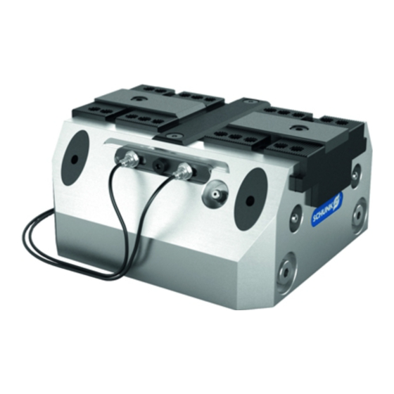
Clamping force block KSP plus-IN, KSP-LH plus-IN, KSP plus-IN2 or KSP-LH plus-IN2 including inductive proximity switch (without top jaws) ACCESSORY PACK: (for contents, see sealing kit and parts list)( 8.1, Page 42) 05.00|21151452 KSP plus-IN, KSP-LH plus-IN, KSP plus-IN2, KSP-LH plus-IN2 |en... -
Page 7: Accessories
(see catalog or data sheets when ordering separately) Top jaw blanks, type: STR, KTR Supporting jaws, type: TBA-G TANDEM Base plates Valves, pneumatic screws Extension cable for INW inductive proximity switch Retrofitting kit IN2 05.00|21151452 KSP plus-IN, KSP-LH plus-IN, KSP plus-IN2, KSP-LH plus-IN2 |en... -
Page 8: Basic Safety Notes
• Structural changes should only be made with the written approval of SCHUNK. Spare parts Use of unauthorized spare parts 05.00|21151452 KSP plus-IN, KSP-LH plus-IN, KSP plus-IN2, KSP-LH plus-IN2 |en... -
Page 9: Use Of Special Chuck Jaws
Basic safety notes Using unauthorized spare parts can endanger personnel and damage the product or cause it to malfunction. • Use only original spare parts or spares authorized by SCHUNK. Use of special chuck jaws Requirements of the chuck jaws When using special chuck jaws, please observe the following rules: •... -
Page 10: Personnel Qualification
• Observe the valid safety and accident prevention regulations. • Wear protective gloves to guard against sharp edges and corners or rough surfaces. • Wear heat-resistant protective gloves when handling hot surfaces. 05.00|21151452 KSP plus-IN, KSP-LH plus-IN, KSP plus-IN2, KSP-LH plus-IN2 |en... -
Page 11: Notes On Safe Operation
• When handling heavy weights, use lifting equipment to lift the product and transport it by appropriate means. • Secure the product against falling during transportation and handling. • Stand clear of suspended loads. 05.00|21151452 KSP plus-IN, KSP-LH plus-IN, KSP plus-IN2, KSP-LH plus-IN2 |en... -
Page 12: Malfunctions
Incorrect handling and assembly Incorrect handling and assembly may impair the product's safety and cause serious injuries and considerable material damage. • Have all work carried out by appropriately qualified personnel. 05.00|21151452 KSP plus-IN, KSP-LH plus-IN, KSP plus-IN2, KSP-LH plus-IN2 |en... -
Page 13: Protection During Commissioning And Operation
Before starting up the machine or automated system, check that the EMERGENCY STOP system is working. Prevent operation of the machine if this protective equipment does not function correctly. 05.00|21151452 KSP plus-IN, KSP-LH plus-IN, KSP plus-IN2, KSP-LH plus-IN2 |en... -
Page 14: Notes On Particular Risks
• Make sure the clamping block and chuck jaws do not fall during transport, installation or removal. • Use a crane and/or a transport truck for transportation. • Only install the clamping block on machines with the appropriate connection dimensions. 05.00|21151452 KSP plus-IN, KSP-LH plus-IN, KSP plus-IN2, KSP-LH plus-IN2 |en... - Page 15 CAUTION Risk of burns due to workpieces with high temperatures. • Wear protective gloves when removing the workpieces. • Automatic loading is preferred. 05.00|21151452 KSP plus-IN, KSP-LH plus-IN, KSP plus-IN2, KSP-LH plus-IN2 |en...
-
Page 16: Technical Data
*** End position spread after 100 consecutive strokes. KSP plus-IN, KSP-LH plus-IN, KSP plus-IN2, KSP-LH plus-IN2 Dimension Ø C 6H7 x 12 8H7 x 14 10H7 x 20 29.5 34.5 59.7 92.6 139.6 69.2 82.2 98.2 05.00|21151452 KSP plus-IN, KSP-LH plus-IN, KSP plus-IN2, KSP-LH plus-IN2 |en... - Page 17 27.5 … 42.5 14 … 20 14 … 22 27.5 … 42.5 W (only IN2) 65.8 72.8 134.8 X (only IN2) 82.1 124.5 Y (only IN2) 63.5 87.2 Design IN 05.00|21151452 KSP plus-IN, KSP-LH plus-IN, KSP plus-IN2, KSP-LH plus-IN2 |en...
-
Page 18: Tightening Torques For Screws
Screw size M10 M12 M14 M16 M20 M24 Tightening torques (Nm) Tightening torques to mount the chuck piston onto the cylinder piston (screw quality 12.9) Screw size Tightening torques (Nm) 05.00|21151452 KSP plus-IN, KSP-LH plus-IN, KSP plus-IN2, KSP-LH plus-IN2 |en... -
Page 19: Assembly
13) must always face downwards. • Surface "X" is parallel to the guideway of the base jaws (item 2) so the clamping block can be aligned on the machine table. 05.00|21151452 KSP plus-IN, KSP-LH plus-IN, KSP plus-IN2, KSP-LH plus-IN2 |en... -
Page 20: Connecting The Clamping Block
Risk of workpiece loss and damage to system due to loss of air pressure caused by damaged pneumatic lines. Always make sure the connections are tight, and use appropriate protection covers to protect the pneumatic hoses and lines from hot chips. 05.00|21151452 KSP plus-IN, KSP-LH plus-IN, KSP plus-IN2, KSP-LH plus-IN2 |en... - Page 21 KSPplus 250-IN and IN2, KSP-LH plus 250-IN and IN2: G1/8" NOTE: All four air connections come sealed on delivery of the clamping force block. On base side with set-screws (item 23) and on front with locking screws (item 11). 05.00|21151452 KSP plus-IN, KSP-LH plus-IN, KSP plus-IN2, KSP-LH plus-IN2 |en...
-
Page 22: Mounting The Clamping Block On The Base Plate
III, IV) and insert the O-rings from the accessory pack into the recesses for the air feed-throughs. • Mount the clamping block onto the base plate. NOTE: The TANDEM base plates do not have a connection possibility for 05.00|21151452 KSP plus-IN, KSP-LH plus-IN, KSP plus-IN2, KSP-LH plus-IN2 |en... -
Page 23: Monitoring Of The Jaw Position Via Inductive Proximity Switches
• Tighten the counter nut for clamping the sensor using a suitable tool and moderate manual force. • Do not exceed the permissible bending radius of the cable (☞ catalog specifications) 05.00|21151452 KSP plus-IN, KSP-LH plus-IN, KSP plus-IN2, KSP-LH plus-IN2 |en... - Page 24 (npn, pnp) is permissible, though this does not increase the permissible load current. • Please note that the leakage current of the individual sensors is accumulative (by about 2 mA). 05.00|21151452 KSP plus-IN, KSP-LH plus-IN, KSP plus-IN2, KSP-LH plus-IN2 |en...
-
Page 25: Basic Construction And Dimensions Of The Inductive Proximity Switches With Scew-Fastened Connection Cable
Basic construction and dimensions of the inductive proximity switches with scew-fastened connection cable Dimensions IN Dimensions IN2: IN S-M8-1 left and IN S-M8-2 right 5.5.2 Dimensions and switching functions of the INW 50 / S-M12 05.00|21151452 KSP plus-IN, KSP-LH plus-IN, KSP plus-IN2, KSP-LH plus-IN2 |en... -
Page 26: Dimensions And Switching Functions Inw 80 / S-M12
Thread at connection plug of supply M12 x 1 cable: Protection class in accordance with DIN IP 67* 60529: *) only when screwed in place in case of circular connector 05.00|21151452 KSP plus-IN, KSP-LH plus-IN, KSP plus-IN2, KSP-LH plus-IN2 |en... -
Page 27: Dimensions And Switching Function Of The In S-M8-1
* for the pin terminal only when screwed on 5.5.5 Dimensions and switching function of the IN S-M8-2 Dimensions and switching function of the IN S-M8-2 Connection colors Pin 1: Brown Pin 3: Blue Pin 4: Black 05.00|21151452 KSP plus-IN, KSP-LH plus-IN, KSP plus-IN2, KSP-LH plus-IN2 |en... -
Page 28: Assembly And Adjustment Of The Proximity Switches
(item 34) into the counter-support with the sensor facing forward so that the switches are flush or protrude slightly. Tighten the retaining plate (item 31) using the 05.00|21151452 KSP plus-IN, KSP-LH plus-IN, KSP plus-IN2, KSP-LH plus-IN2 |en... - Page 29 When making the adjustment, make sure that the signal LED on the sensor is easily visible. Then fasten the proximity switch to the retainer plate (item 31) using the counter nut. IN sensor assembly 05.00|21151452 KSP plus-IN, KSP-LH plus-IN, KSP plus-IN2, KSP-LH plus-IN2 |en...
- Page 30 Both proximity switches must be installed in the operating condition to prevent chips from entering the clamping system through the open clamp. 05.00|21151452 KSP plus-IN, KSP-LH plus-IN, KSP plus-IN2, KSP-LH plus-IN2 |en...
-
Page 31: Circuit And Functional Diagram For External Workpiece Clamping
The circuit diagram can also be adjusted for monitoring "Stroke end position closed" and "Missed clamping position." The proximity switches can also be individually adjusted on the retaining plate. Fig.°5 Circuit diagram for external workpiece clamping 05.00|21151452 KSP plus-IN, KSP-LH plus-IN, KSP plus-IN2, KSP-LH plus-IN2 |en... - Page 32 Assembly Fig.°6 Functional diagram for external workpiece clamping 05.00|21151452 KSP plus-IN, KSP-LH plus-IN, KSP plus-IN2, KSP-LH plus-IN2 |en...
-
Page 33: Circuit And Functional Diagram For Internal Workpiece Clamping
The circuit diagram can also be adjusted for monitoring "Stroke end position open" and "Missed clamping position." The proximity switches can also be individually adjusted on the retaining plate. Fig.°7 Circuit diagram for internal workpiece clamping 05.00|21151452 KSP plus-IN, KSP-LH plus-IN, KSP plus-IN2, KSP-LH plus-IN2 |en... - Page 34 Assembly Fig.° 8 Functional diagram for internal workpiece clamping 05.00|21151452 KSP plus-IN, KSP-LH plus-IN, KSP plus-IN2, KSP-LH plus-IN2 |en...
-
Page 35: Troubleshooting
Check maintenance unit, perform maintenance Place oiler closer to clamping system Set required oil level Chuck piston screw broken (overload) Send clamping system to SCHUNK for repairs or disassemble clamping system and repair using ( 7.1, Page 38) original SCHUNK spare parts... - Page 36 Lubricate the lubrication nipples with LINO MAX ( 7, Page 37) Clamping block movement jerky Possible cause Remedial measures Steel guide rollers on sliding surfaces See chapter "Maintenance and Care" ( 7, Page 37) not greased 05.00|21151452 KSP plus-IN, KSP-LH plus-IN, KSP plus-IN2, KSP-LH plus-IN2 |en...
-
Page 37: Maintenance And Care
The clamping force should not drop during this period. Please adjust the inspection interval to the operating conditions of the clamping device, however, we do recommend conducting a check every 5,000 clamping cycles at the latest. 05.00|21151452 KSP plus-IN, KSP-LH plus-IN, KSP plus-IN2, KSP-LH plus-IN2 |en... -
Page 38: Disassembling And Assembling The Clamping Block
8 Pull the base jaws (item 2) out of the housing (item 1). 9 Before pulling off the cover (item 5), all the screws (item 21) need to be removed. To take off the cover (5), screw two 05.00|21151452 KSP plus-IN, KSP-LH plus-IN, KSP plus-IN2, KSP-LH plus-IN2 |en... - Page 39 Be sure to observe the installation position for the base jaws and the chuck piston. 26 Connect the clamping system to the air supply and move the jaws to the OPEN position. 05.00|21151452 KSP plus-IN, KSP-LH plus-IN, KSP plus-IN2, KSP-LH plus-IN2 |en...
-
Page 40: Leak Test
5 After 24 hours, the clamping force block is: - sealed if the pressure gauge indicates a drop in pressure of less than 0.5 bar - leaking if the pressure gauge indicates a drop 05.00|21151452 KSP plus-IN, KSP-LH plus-IN, KSP plus-IN2, KSP-LH plus-IN2 |en... - Page 41 Metaflux leak detection spray). Seal any leaking screws. Once the screws are sealed, check for leaks and replace if necessary (see Disassembling and assembling the clamping block ( 7.1, Page 38)). 05.00|21151452 KSP plus-IN, KSP-LH plus-IN, KSP plus-IN2, KSP-LH plus-IN2 |en...
-
Page 42: Sealing Kits, Accessory Packs And Parts Lists
Quad ring, 126.59 x 3.53 Combined sealing ring O-ring, DIN 3771 150 x 2.00 O-ring, DIN 3771 12 x 2.00 Flat seal Flat seal O-ring, DIN 3771 6 x 1.50 05.00|21151452 KSP plus-IN, KSP-LH plus-IN, KSP plus-IN2, KSP-LH plus-IN2 |en... -
Page 43: Accessory Packs
Screw, DEI 4762/10.9 M10 x 35 mm Clamping sleeve, DIN EN ISO 13337 DRM 13 x 18 Screw, DEI 4762/12.9 M8 x 20 mm O-ring, DIN 3771 6 x 1.50 05.00|21151452 KSP plus-IN, KSP-LH plus-IN, KSP plus-IN2, KSP-LH plus-IN2 |en... -
Page 44: Parts Lists
Combined sealing element Screw, DIN 7984/8.8 M6 x 10 mm 17** O-ring, DIN 3771 93 x 2.00 18*** O-ring, DIN 3771 9 x 2.00 19*** Screw, DEI 4762/10.9 M8 x 35 mm 05.00|21151452 KSP plus-IN, KSP-LH plus-IN, KSP plus-IN2, KSP-LH plus-IN2 |en... - Page 45 8*** Plug 9*** Fitting screw, 10f7/M8 Funnel lubrication nipple Locking screw 12** Quad ring, 72.62 x 3.53 Sound absorber Screw, DEI 4762/10.9 M8 x 20 mm 15** Combined sealing element 05.00|21151452 KSP plus-IN, KSP-LH plus-IN, KSP plus-IN2, KSP-LH plus-IN2 |en...
- Page 46 ** See sealing kit list – parts cannot be ordered individually *** Contained in accessory kit KSP plus 160-IN, KSP-LH plus 160-IN Item Designation Quantity Body Base jaw Chuck piston Cylinder piston Cover Guide strip Covering strip 8*** Plug 05.00|21151452 KSP plus-IN, KSP-LH plus-IN, KSP plus-IN2, KSP-LH plus-IN2 |en...
- Page 47 ** See sealing kit list – parts cannot be ordered individually *** Contained in accessory kit KSP plus 160-IN2, KSP-LH plus 160-IN2 Item Designation Quantity Body Base jaw Chuck piston 05.00|21151452 KSP plus-IN, KSP-LH plus-IN, KSP plus-IN2, KSP-LH plus-IN2 |en...
- Page 48 KA BW8-L 3P-0500 O-ring, DIN 3771 5.5 x 1.50 Cover SBG 160-1.5 Connector M12 BCC02H9 * Individual components are specially tuned to one another and cannot be replaced by the customer. 05.00|21151452 KSP plus-IN, KSP-LH plus-IN, KSP plus-IN2, KSP-LH plus-IN2 |en...
- Page 49 Countersunk screw, DIN EN ISO 10642/10.9 M6 x 12 mm 2 Set-screw, similar to DIN EN ISO 4026/45H M5 x 5 mm IN6RD/VZ/PA 27*** Clamping sleeve, DIN EN ISO 13337 DRM 16 x 22 Retaining plate Counter-support Washer 05.00|21151452 KSP plus-IN, KSP-LH plus-IN, KSP plus-IN2, KSP-LH plus-IN2 |en...
- Page 50 Countersunk screw, DIN EN ISO 10642/10.9 M5 x 20 mm 19 22** Flat seal Set-screw, similar to DIN EN ISO 4026/45H M5 x 4 mm Set-screw, similar to DIN EN ISO 4026/45H M6 x 6 mm IN6RD/VZ/PA 05.00|21151452 KSP plus-IN, KSP-LH plus-IN, KSP plus-IN2, KSP-LH plus-IN2 |en...
-
Page 51: Proximity Switches And Supply Cables Variant In For Single Or Replacement Orders
If required, the single components for the two-part INW inductive proximity switch can be ordered separately. The supply cable is available in two connecting lengths. IN inductive proximity switch - M12 plug connector 05.00|21151452 KSP plus-IN, KSP-LH plus-IN, KSP plus-IN2, KSP-LH plus-IN2 |en... -
Page 52: Proximity Switches And Supply Cables Variant In2 For Single Or Replacement Orders
1349990 Angular plug KA – M12 plug connection Designation ID number KA BW8-L 3P-0500 (cable length 1350000 5 m) Self-converted plug connector M12 Designation ID number Connector M12 BCC02H9 1154135 05.00|21151452 KSP plus-IN, KSP-LH plus-IN, KSP plus-IN2, KSP-LH plus-IN2 |en... -
Page 53: Assembly Drawing
Assembly drawing Assembly drawing Size 160 for sizes 160/250 Centering with clamping **** Centering with fitting screws sleeves 05.00|21151452 KSP plus-IN, KSP-LH plus-IN, KSP plus-IN2, KSP-LH plus-IN2 |en... -
Page 54: Translation Of The Original Declaration Of Incorporation
The relevant technical documentation according to Annex VII, Part B, belonging to the partly completed machinery, has been created. Person authorized to compile the technical documentation: Philipp Schräder, Address: see manufacturer's address Mengen, May 2018 p.p. Philipp Schräder; Head of Engineering Design 05.00|21151452 KSP plus-IN, KSP-LH plus-IN, KSP plus-IN2, KSP-LH plus-IN2 |en... -
Page 55: Appendix On Declaration Of Incorporation, As Per 2006/42/Ec, Annex Ii, No. 1 B
Risks related to moving parts 1.3.8 Choice of protection against risks arising from moving parts 1.3.8.1 Moving transmission parts 1.3.8.2 Moving parts involved in the process 1.3.9 Risks of uncontrolled movements 05.00|21151452 KSP plus-IN, KSP-LH plus-IN, KSP plus-IN2, KSP-LH plus-IN2 |en... - Page 56 Supplementary essential health and safety requirements to offset hazards due to lifting operations Supplementary essential health and safety requirements for machinery intended for underground work Supplementary essential health and safety requirements for machinery presenting particular hazards due to the lifting of persons 05.00|21151452 KSP plus-IN, KSP-LH plus-IN, KSP plus-IN2, KSP-LH plus-IN2 |en...
Need help?
Do you have a question about the KSP plus-IN and is the answer not in the manual?
Questions and answers