Table of Contents
Advertisement
OEM PRODUCT DESIGN GUIDE
NVIDIA Jetson TX2/TX2i
Abstract
This document contains recommendations and guidelines for Engineers to follow to create a product that is optimized
to achieve the best performance from the common interfaces supported by the NVIDIA
on-Module (SOM).
This document provides detailed information on the capabilities of the hardw are module, w hich may differ from
supported configurations by provided softw are. Refer to softw are release documentation for information on supported
capabilities.
Jetson TX2 & Jetson TX2i modules utilize Tegra X2 which is a Parker series SoC.
Notes:
JETSON TX2/TX2i OEM PRODUCT | DESIGN GUIDE | 20180618
®
Jetson™ TX2/TX2i System-
1
Advertisement
Table of Contents

Subscribe to Our Youtube Channel
Related Manuals for Nvidia Jetson TX2


Summary of Contents for Nvidia Jetson TX2
- Page 1 Refer to softw are release documentation for information on supported capabilities. Jetson TX2 & Jetson TX2i modules utilize Tegra X2 which is a Parker series SoC. Notes: JETSON TX2/TX2i OEM PRODUCT | DESIGN GUIDE | 20180618...
- Page 2 Remov ed Jetson TX1 mention in document except note in USB, PCIe & SATA section refering to the Jetson TX1/TX2 Comparison & Migration AN for differences in lane mapping support. Abstract JETSON TX2/TX2i OEM PRODUCT | DESIGN GUIDE | 20180618...
- Page 3 Added paragraph related to potential differences between hardware capabilities and support in released sof tware. References Added Jetson TX2/TX2i & Jetson TX1/TX2 Comparison & Migration App Notes. Power Updated to to add separate Power-Up sequence figures and timing tables for Power-button cases & Auto- power-on cases &...
-
Page 4: Table Of Contents
11.0 WLAN / BT (INT EGRAT ED) – JET SON TX2 ONL Y .......................61 12.0 MISCELLANEOUS I NT ERFACES............................63 12.1 I2C ......................................63 12.2 SPI ......................................65 12.3 UART .....................................67 12.4 Fan ......................................69 12.5 CAN .......................................69 12.6 Debug....................................71 12.7 Strapping Pins ..................................72 13.0 PADS ......................................75 JETSON TX2/TX2i OEM PRODUCT | DESIGN GUIDE | 20180618... - Page 5 18.3 Driver Characteristics ................................91 18.4 Receiver Characteristics..............................91 18.5 Transm ission Lines & Reference Planes ........................91 19.0 APPENDIX D: DESIGN GUIDELINE GL OSSARY .........................94 20.0 APPENDIX E: JETSON T X2/TX2I PIN DESCRI PTIONS .......................95 JETSON TX2/TX2i OEM PRODUCT | DESIGN GUIDE | 20180618...
-
Page 6: Introduction
Park er Series SoC Technical Reference Manual Jetson TX1/TX2 Dev eloper Kit Carrier Board Specification Jetson TX2i Module Pinmux Jetson TX2 and Jetson TX2i Comparison and Migration Application Note Jetson TX1 and Jetson TX2 Comparison and Migration Application Note Jetson TX2i Thermal Design Guide... -
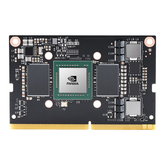
Page 7: Jetson Tx2/Tx2I
NVIDIA Jetson TX2/TX2i OEM Product Design Guide 2.0 JETSON TX2/TX2i 2.1 Overview The Jetson TX2/TX2i module resides at the center of the embedded system solution and includes: Power (PMIC/Regulators, etc.) Ethernet PHY DRAM (LPDDR4) Power & Voltage Monitors eMMC Thermal Sensor Connects to WLA N and Bluetooth enabled dev ices (TX2 only ) In addition, a range of interfaces are available at the main connector for use on the carrier board as show n in the follow ing table. - Page 8 Signals starting with “GPIO_” are standard GPIOs that hav e been assigned recommended usage. If the assigned usage is required in a design, it is recommended the matching GPIO be used. If the assigned usage is n ot required, the pins may be used as GPIOs for other purposes. JETSON TX2/TX2i OEM PRODUCT | DESIGN GUIDE | 20180618...
-
Page 9: Power
3.0 POWER Caution Jetson TX2/TX2i is not hot-pluggable. Before installing or removing the module, the main power supply (to VDD_IN pins) must be disconnected and adequate time (recommended > 1 minute) must be allowed for the various power rails to fully discharge. -
Page 10: Supply Allocation
WiFi / BT (TX2 only) to support Auto-Power-On Jets on TX 2 To Carrier Board Power-on circuitry MOD_PWR_CFG _ID (B49 on Jetson TX2 is RSVD – No Connect) Jets on TX 2i 3.1 Supply Allocation Table 6 Internal Power Subsystem Allocation Power Rails... -
Page 11: Main Power Sources/Supplies
VDD_IN supply is stable and it is possible to pow er up any standby circuits on the module. This signal prevents the Tegra processor from pow ering up prematurely before the Carrier Board has charged up its decoupling capacitors and pow er to the module is stable JETSON TX2/TX2i OEM PRODUCT | DESIGN GUIDE | 20180618... - Page 12 Note: Measured from VDD_IN ramp start to POWER_BTN# ramp start. Carrier board dependent. Typical value using NVIDIA P2597, measured from VDD_IN ramp start to VIN_PWR_BAD# inactive start. Carrier board dependent. User Dependent if POWER_BTN# connected to button. Otherwise, carrier board dependent.
- Page 13 POWER_BTN# is de-asserted. This is due to the difference in the PMIC power on signal (edge triggered on Jetson TX2 PMIC & level sensitive on Jetson TX2i. When Jetson TX2i is used in a P2597_C02 compatible carrier board, logic on the carrier board simulates edge triggered power-on so the power button will function the same as for Jetson TX2.
- Page 14 Typical value measured using NVIDIA P2597. Measured from CARRIER_PWR_ON to carrier board VDD_1V8 ramp down start. Carrier board dependent. Typical value measured using NVIDIA P2597. Meas ured from CARRIER_PWR_ON ramp down start to the module main 1.8V ramp down start.
-
Page 15: Power Discharge
3.5 Module Power-on Type Detection & Control The follow ing describes w hat is required in a carrier board design to support Jetson TX2 and Jetson TX2i in a design that requires a pow er button press to pow er the system on. If a design requires the system to pow er on immediately after the main pow er supply is connected/enabled, see the “Optional Auto-Pow er-On Support”... - Page 16 NVIDIA Jetson TX2/TX2i OEM Product Design Guide w hich is floating on Jetson TX2 w ill be grounded on the Jetson TX2i as a means to differentiate betw een the tw o module types. MOD_PWR_CFG_ID The module pow er configuration identification pin ( ) resides on the Module Pin B49.
-
Page 17: Power & Voltage Monitoring
VDD_IN w ith a 5V reference. This device has an open drain active low output w hich is pulled low w hen the VDD_IN voltage drops below the selected threshold (8.04V). JETSON TX2/TX2i OEM PRODUCT | DESIGN GUIDE | 20180618... -
Page 18: Deep Sleep (Sc7)
3.7 Deep Sleep (SC7) Jetson TX2/TX2i supports a low pow er state called Deep Sleep or SC7. This can be entered under softw are control, and exited using various mechanisms, including w ake capable pins that are listed in the table below . -
Page 19: Optional Auto-Power-On Support
3.8 Optional Auto-Power-On Support Jetson TX2 and Jetson TX2i both optionally support Auto-Pow er-On. This allow s the platform to pow er on w hen VDD_IN is first pow ered, instead of w aiting for a pow er button press. For Jetson TX2, to enable this feature, the CHARGER_PRSNT# pin should be tied to GND. - Page 20 3.8.2 Jetson TX2i Auto-Power-On Details Jetson TX2i uses a different PMIC than Jetson TX2. The TX2i PMIC has a level sensitive on input, so in order to pow er automatically w hen the main pow er is applied (Auto-Pow er-On), all that is required is for the POWER_BTN# pin to be pulled up.
-
Page 21: General Routing Guidelines
4.0 GENERAL ROUTING GUIDELINES Signal Nam e Conventions The follow ing conventions are used in describing the signals for Jetson TX2/TX2i: ▪ Signal names use a mnemonic to represent the function of the signal. For example, Secure Digital Interface #3 Command signal is represented as SDCARD_CMD, w ritten in bold to distinguish it from other text. - Page 22 Do not route other signals or power traces/areas directly under or over critical high-speed interface signals. Note: The requiements detailed in the Interface Signal Routing Requirements tables must be met for all interfaces implemented or proper operation cannot be guaranteed. JETSON TX2/TX2i OEM PRODUCT | DESIGN GUIDE | 20180618...
-
Page 23: Usb, Pcie & Sata
5.0 USB, PCIE & SATA Jetson TX2/TX2i allow s multiple USB 3.0 & PCIe interfaces, and a single SATA interface to be brought out on the module. In some cases, these interfaces are multiplexed on some of the module pins. - Page 24 Note: PCIe interface #2 can be brought to the PEX1 pins, or USB 3.0 port #1 to the USB_SS0 pins on Jetson TX2/TX2i depending on the setting of a multiplexor on the module. The selection is controlled by QSPI_IO2 configured as a GPIO.
-
Page 25: Usb
Note: PCIe interface #2 can be brought to the PEX1 pins, or USB 3.0 port #1 to the USB_SS0 pins on Jetson TX2/TX2i depending on the setting of a multiplexor on the module. The selection is controlled by QSPI_IO2 configured as a GPIO. - Page 26 Adjustments to the USB drive strength, slew rate, termination value settings should not be necessary, but if any are made, they MUST be done as an offset to default values instead of overwriting those values. JETSON TX2/TX2i OEM PRODUCT | DESIGN GUIDE | 20180618...
- Page 27 This is the recommended dimension for meeting NEXT (between TX/RX) Main-route height NEXT requirement Min Inter-S Breakout Intra-pair This is the recommended dimension for meeting FEXT NEXT requirement (between TX/TX or RX/RX) spacing Main-route JETSON TX2/TX2i OEM PRODUCT | DESIGN GUIDE | 20180618...
- Page 28 Max Junction capacitance (IO to GND) Footprint Pad should be on the net – not trace stub Location (max length to adjacent discontinuity) 8 (53) mm (ps) Discontinuity is connector, via, or component pad JETSON TX2/TX2i OEM PRODUCT | DESIGN GUIDE | 20180618...
- Page 29 Near the module connector & USB device. USB connector pins can serve as test points. One for each of the USB 3.0 output lines used (TXn_+/-) Near USB device. USB connector pins can serve as test points JETSON TX2/TX2i OEM PRODUCT | DESIGN GUIDE | 20180618...
-
Page 30: Pcie
One for each of the USB 3.0 input lines (RX_+/-) Near the module connector. 5.2 PCIe Jetson TX2/TX2i contains a PCIe (PEX) controller that supports up to 5 lanes, and 3 Root-Port (RP) controllers. Figure 17. PCIe Connection Example Jetson TX2/TX2i... - Page 31 Longer trace lengths may be possible if the total trace loss is equal to or better than the target. If the loss is greater, the max trace lengths will need to be reduced. Do length matching before Via transitions to different layers or any discontinuity to minimize common mode conversion. JETSON TX2/TX2i OEM PRODUCT | DESIGN GUIDE | 20180618...
- Page 32 One for each of the PCIe TX_+/– output lines used. Near PCIe device. Connector pins may serve as test points if accessible. One for each of the PCIe RX_+/– input lines used. Near the module connector. JETSON TX2/TX2i OEM PRODUCT | DESIGN GUIDE | 20180618...
-
Page 33: Sata
NVIDIA Jetson TX2/TX2i OEM Product Design Guide 5.3 SATA A Gen 2 SATA controller is implemented on Jetson TX2/TX2i. The interface is brought to the module connector as show n in the figure below . Figure 18. SATA Connection Example... - Page 34 Note: If routing to SATA device or SATA connector includes a flex or 2 PCB, the total routing including all PCBs/flexes must be used for the max trace & skew calculations JETSON TX2/TX2i OEM PRODUCT | DESIGN GUIDE | 20180618...
- Page 35 One for each of the SATA_TX_+/– output lines. Near SATA device. Connector pins may serve as test points if accessible. One for each of the SATA_RX_+/– input lines. Near the module connector. JETSON TX2/TX2i OEM PRODUCT | DESIGN GUIDE | 20180618...
-
Page 36: Gigabit Ethernet
NVIDIA Jetson TX2/TX2i OEM Product Design Guide 6.0 GIGABIT ETHERNET Jetson TX2/TX2i integrates a BCM54610C1IMLG Ethernet PHY. The magnetics & RJ45 connector are implemented on the Carrier board. Contact Broadcom for the Carrier board placement/routing guidelines. Table 29. Gigabit Ethernet Pin Descriptions... - Page 37 Not used Table 32. Recommended Gigabit Ethernet observation (test) points for initial boards Test Points Recommended Location One for each of the MDI[3:0]+/– lines. Near the module connector & Magnetics device. JETSON TX2/TX2i OEM PRODUCT | DESIGN GUIDE | 20180618...
-
Page 38: Display
7.1 MIPI DSI Jetson TX2/TX2i supports eight total MIPI DSI data lanes. Each data lane has a peak bandw idth up to 1.5Gbps. The lanes can be configured in Dual Link & Split Link modes. The follow ing configurations are possible: Dual Link Mode (Up to 8 PHY lanes): ▪... - Page 39 DSI_C_D0_P D0_P DSI2_D0– DSI_C_D0_N D0_N Lanes DSI2_D1+ DSI_C_D1_P D1_P DSI2_D1– DSI_C_D1_N D1_N DSI3_CK+ DSI_D_CLK_P CLK_P DSI3_CK– DSI_D_CLK_N CLK_N DSI3_D0+ DSI_D_D0_P D0_P DSI3_D0– DSI_D_D0_N D0_N Lanes DSI3_D1+ DSI_D_D1_P D1_P DSI3_D1– DSI_D_D1_N D1_N JETSON TX2/TX2i OEM PRODUCT | DESIGN GUIDE | 20180618...
- Page 40 Near display. Panel connector pins can be used if accessible. Note: Test points must be done carefully to minimize signal integrity impact. Avoid stubs & keep pads small & near signal traces JETSON TX2/TX2i OEM PRODUCT | DESIGN GUIDE | 20180618...
-
Page 41: Edp / Dp / Hdmi
NVIDIA Jetson TX2/TX2i OEM Product Design Guide 7.2 eDP / DP / HDMI Jetson TX2/TX2i includes tw o interfaces (DP0 & DP1). Both support eDP / DP or HDMI. See Jetson TX2/TX2i Data Sheet for the maximum resolution supported. Table 38. HDMI / eDP / DP Pin Descriptions... - Page 42 <=1.2 HBR2 @ 2.7GHz <=2.4 Resonance dip frequency >8 TDR dip >85 Ω @ Tr-200ps (10%-90%) FEXT @ DC <= -40dB IL/FEXT plot – up to HBR2 @ 2.7GHz <= -30dB JETSON TX2/TX2i OEM PRODUCT | DESIGN GUIDE | 20180618...
- Page 43 The via dimension must be required for the HDMI- ≥92 Ω @ 35ps DP co-layout condition. Recommende d via dimens ion Drill/Pad 200/400 for impedance control Antipad >840 Via pitch ≥880 JETSON TX2/TX2i OEM PRODUCT | DESIGN GUIDE | 20180618...
- Page 44 The average of the differential signals is used for length matching. Do not perform length matching within breakout region. Recommend doing trace length matching to <1ps before Vias or any discontinuity to minimize common mode conversion JETSON TX2/TX2i OEM PRODUCT | DESIGN GUIDE | 20180618...
- Page 45 5V0_HDMI_EN Note: Level shifters required on DDC/HPD. Jetson TX2/TX2i pads are not 5V tolerant & cannot directly meet HDMI V requirements. HPD level shifter can be non-inverting or inverting. If EMI/ESD devices are necessary, they must be tuned to minimize the impact to signal quality, which must meet the timing &...
- Page 46 Reference plane Trace spacing/Length/Skew Trace loss characteristic: < 0.8 dB/in. @ 3GHz The max length is derived based on this characteristic. < 0.4 dB/in. @ 1.5GHz See note 1. JETSON TX2/TX2i OEM PRODUCT | DESIGN GUIDE | 20180618...
- Page 47 ≤ 4 vias Max Via Stub Length long via stub requires review (IL & resonance dip check) Serpentine Min bend angle deg (a) JETSON TX2/TX2i OEM PRODUCT | DESIGN GUIDE | 20180618...
- Page 48 GND/PWR void under/above cap is preferred Common-Mode Choke (Stuffing option – not added unless EMI issue is seen) TDK ACM2012D-900-2P Common-mode Ω impedance @ 100MHz <=0.3ohm Differential TDR impedance 90ohm +/-15% @ Tr=200ps (10%-90%) JETSON TX2/TX2i OEM PRODUCT | DESIGN GUIDE | 20180618...
- Page 49 If routing includes a flex or 2 PCB, the max trace delay & skew calculations must include all the PCBs/flex routing. Solutions with flex/2 PCB may not achieve maximum frequency operation. JETSON TX2/TX2i OEM PRODUCT | DESIGN GUIDE | 20180618...
- Page 50 10kΩ DP_AUX_CHx_P DP_AUX To DP Connector Gated 100kΩ 100kΩ 0.1uF 3.3V To Jetson TX2/TX2i DP_MODE* 100kΩ DP_AUX_CHx_N DP_AUX* 100kΩ 0.1uF DP Interface Signal Routing Requirem ents See eDP/DP Signal Routing Requirements. JETSON TX2/TX2i OEM PRODUCT | DESIGN GUIDE | 20180618...
-
Page 51: Mipi Csi (Video Input)
8.0 MIPI CSI (VIDEO INPUT) Jetson TX2/TX2i supports three MIPI CSI x4 bricks, allow ing a variety of device types and combinations to be supported. Up to three quad lane cameras or six dual lane cameras are possible (see CSI Configurations table for details). Each data lane has a peak bandw idth of up to 2.5Gbps. - Page 52 Any EMI/ESD devices must be tuned to minimize impact to signal quality and meet the timing & Vil/Vih requirements at the receiver & maintain signal quality and meet requirements for the frequencies supported by the design . JETSON TX2/TX2i OEM PRODUCT | DESIGN GUIDE | 20180618...
- Page 53 Depending on the mechanical design of the platform and camera modules, ESD protection may be necessary. In addition, EMI control may be needed. Both are shown in the Camera Connection Example diagram. Any EMI/ESD solution must be compatible with the frequency required by the design. JETSON TX2/TX2i OEM PRODUCT | DESIGN GUIDE | 20180618...
- Page 54 Location One per signal line. Near the module pins Note: Test points must be done carefully to minimize signal integrity impact. Avoid stubs & keep pads small & near signal traces JETSON TX2/TX2i OEM PRODUCT | DESIGN GUIDE | 20180618...
-
Page 55: Sdio/Sdcard/Emmc
NVIDIA Jetson TX2/TX2i OEM Product Design Guide 9.0 SDIO/SDCARD/EMMC Jetson TX2/TX2i has four SD/MMC interfaces. The mapping of these interfaces for each module is show n in the SDIO / SD Card / eMMC Interface Mapping table. Table 52. SDMMC Pin Descriptions... - Page 56 If routing to SD Card socket includes a flex or 2nd PCB, max trace & skew calculations must include PCB & flex routing. Table 55. SD Card Loading vs Drive Type General SD Card Compliance Parameter Value Units Notes Spec best case value CARD Spec worst case value JETSON TX2/TX2i OEM PRODUCT | DESIGN GUIDE | 20180618...
- Page 57 Near Device/Connector pin. SD connector pin can be used for device end if accessible. One SDCARD/SDIO_DATx line & one for Near the module & Device pins. SD connector pin can be used for device end if accessible. SDCARD/SDIO_CMD. JETSON TX2/TX2i OEM PRODUCT | DESIGN GUIDE | 20180618...
-
Page 58: Audio
NVIDIA Jetson TX2/TX2i OEM Product Design Guide 10.0 AUDIO Jetson TX2/TX2i brings four PCM/I2S audio interfaces to the module pins & includes a flexible audio-port sw itching architecture. In addition, digital microphone & speaker interfaces are provided. Table 59. Audio Pin Descriptions... - Page 59 Audio Codec Master Clock: Connect to clock pin of Audio Codec. GPIO19_AUD_RST Audio Reset: Connect to reset pin of Audio Codec. GPIO20_AUD_INT Audio Interrupt: Connect to interrupt pin of Audio Codec. JETSON TX2/TX2i OEM PRODUCT | DESIGN GUIDE | 20180618...
- Page 60 Table 64. DMIC Signal Connections Function Name Type Termination Description AO_DMIC_IN_CLK Digital Microphone Clock: Connect to clock pin of DMIC device AO_DMIC_IN_DAT Digital Microphone Data: Connect to data pin of DMIC device JETSON TX2/TX2i OEM PRODUCT | DESIGN GUIDE | 20180618...
-
Page 61: Wlan / Bt (Integrated) - Jetson Tx2 Only
11.0 WLAN / BT (INTEGRATED) – JETSON TX2 ONLY Jetson TX2 integrates a Broadcom BCM4354 WLAN / BT solution. Tw o Dual-band antenna connectors are located on the module. The requirements are in the Antenna Requirements table below . The UART interface is multiplexed and either route these to the WLAN/BT device or to the connector pins for use on the carrier board. - Page 62 Mating Connector Matching I-PEX MHF or Hirose U.FL See note 1 Female Receptacles on Jetson TX2 are from Hirose Electric (U.S.A). Part # is U.FL-R-SMT-1(10). Note: Antenna Manufacturer: Pulse, Part Number: W1043 Cable manufacturer: Pulse, part number: W9009 JETSON TX2/TX2i OEM PRODUCT | DESIGN GUIDE | 20180618...
-
Page 63: Miscellaneous Interfaces
12.0 MISCELLANEOUS INTERFACES 12.1 I2C Tegra has nine I2C controllers. Jetson TX2/TX2i brings eight of the I2C interfaces out, w hich are show n in the tables below . The assignments in Table 67 should be used for the I2C interfaces: Table 66. - Page 64 Fm = Fast-mode, Fm+ = Fast-mode Plus Avoid routing I2C signals near noisy traces, supplies or components such as a switching power regulator. No requirement for decoupling caps for PWR reference JETSON TX2/TX2i OEM PRODUCT | DESIGN GUIDE | 20180618...
-
Page 65: Spi
20 (0x13) 26 (0x19) 98KHz Note: Sm = Standard Mode. 12.2 SPI Jetson TX2/TX2i brings out three of the Tegra SPI interfaces. Table 71. SPI Pin Descriptions Usage on the Carrier Pin # Module Pin Name Tegra Signal Usage/Description Direction... - Page 66 Figure 39. SPI Star Topologies Device #1 Jetson TX2/ Branch-A TX2i Main trunk Device #2 Branch-B Figure 40. SPI Daisy Topologies Device #1 Branch-A Jetson TX2/ TX2i Device #2 Main trunk Branch-B JETSON TX2/TX2i OEM PRODUCT | DESIGN GUIDE | 20180618...
-
Page 67: Uart
12.3 UART Jetson TX2/TX2i brings five UARTs out to the main connector. One of the UARTs is used for the WLAN/BT on Jetson TX2 or as UART3 at the connector depending on the setting of a multiplexor. See Table 76 for typical assignments of the UARTs. - Page 68 UART Receive: Connect to Peripheral TXD pin of device UART[3:0]_CTS# UART Clear to Send: Connect to Peripheral RTS_N pin of device UART[3:0]_RTS# UART Request to Send: Connect to Peripheral CTS pin of device JETSON TX2/TX2i OEM PRODUCT | DESIGN GUIDE | 20180618...
-
Page 69: Fan
NVIDIA Jetson TX2/TX2i OEM Product Design Guide 12.4 Fan Jetson TX2/TX2i provides PWM and Tachometer functionality for controlling a fan as part of the thermal solution. Information on the PWM and Tachometer pins/functions can be found in the follow ing locations: Module Pin Mux: ▪... - Page 70 CAN Receive: Connect to Peripheral pin of device CAN[1:0]_ERR CAN Error: Connect to matching pin of device CAN1_STBY CAN Standby: Connect to matching pin of device CAN_WAKE CAN Wake: Connect to matching pin of device JETSON TX2/TX2i OEM PRODUCT | DESIGN GUIDE | 20180618...
-
Page 71: Debug
JTAG Clock: Connect to TCK pin of connector JTAG_TDO JTAG Data Out: Connect to TDO pin of connector JTAG_TDI JTAG Data In: Connect to TDI pin of connector JTAG_RTCK JTAG Return Clock: Connect to RTCK pin of connector JETSON TX2/TX2i OEM PRODUCT | DESIGN GUIDE | 20180618... -
Page 72: Strapping Pins
12.7 Strapping Pins Jetson TX2/TX2i has one strap (FORCE_RECOV#) that is intended to be used on the carrier board. That strap is used to enter Force Recovery mode. The other straps mentioned in this section are for use on the module by Nvidia only. They are included here as their state at pow er-on must be kept at the level selected on the module. - Page 73 If UART7_TX (on RSVD pin) is used in a design, it must not be driven or pulled high during power-on as this would affect the BOOT_SELECT strapping. Violating this requirement will likely prevent the system from booting. JETSON TX2/TX2i OEM PRODUCT | DESIGN GUIDE | 20180618...
- Page 74 Tegra UART4_TX & UART4_RTS_N are routed to a mux on Jetson TX2 and directed to either UART3_TX/RTS or On-module WLAN/BT. Since these pins are outputs, and the mux is in the path, Jetson TX2 UART3 pins will not affect the Boot Select [1:0] strapping. On Jetson used in a design, they must not TX2i, the Tegra UART4 pins are routed directly to the UART3 pins on the module.
-
Page 75: Pads
13.4 Pins Pulled/Driven High During Power-on Jetson TX2/TX2i is pow ered up before the carrier board (See Pow er Sequencing section). The table below lists the pins on the module that default to being pulled or driven high. Care must be taken on the carrier board design to ensure that any of these pins that connect to devices on the carrier board (or devices connected to the carrier board) do not cause damage or excessive leakage to those devices. -
Page 76: Pad Drive Strength
+/- 1mA LV_CZ 0.15*VDD 0.85*VDD +/- 2mA 0.15*VDD 0.7*VDD +/- 2mA 0.175*VDD 0.7*VDD +/- 2mA CZ (1.8V mode) 0.25*VDD 0.75*VDD +/- 2mA CZ (3.3V mode) 0.15*VDD 0.75*VDD +/- 2mA LV_CZ 0.25*VDD 0.75*VDD JETSON TX2/TX2i OEM PRODUCT | DESIGN GUIDE | 20180618... -
Page 77: Unused Interface Terminations
14.1 Unused MPIO Interfaces The follow ing Jetson TX2/TX2i pins (& groups of pins) are MPIO (Multi-purpose Standard CMOS Pad) pins that support either special function IOs (SFIO) and/or GPIO capabilities. Any unused pins or portions of pin groups listed below that are not used can be left unconnected. -
Page 78: Design Checklist
SDCARD_CD# Internal pull-up to 1.8V – SDCARD_WP Internal pull-up to 1.8V – SD Card SDIO_CMD Internal pull-up to 1.8V SDIO_D[3:0] Internal pull-up to 1.8V Embedded Display LCD_TE Internal pull-down – GPIO JETSON TX2/TX2i OEM PRODUCT | DESIGN GUIDE | 20180618... - Page 79 0.1uF capacitors if directly connected USB_SS1_RX+/- – 0.1uF capacitors directly connected PEX0_TX+/- – 0.1uF capacitors PEX1_TX+/- – 0.1uF capacitors PEX2_TX+/- – 0.1uF capacitors PEX_RFU_TX+/- – 0.1uF capacitors PEX0_RX+/- – 0.1uF capacitors if directly connected JETSON TX2/TX2i OEM PRODUCT | DESIGN GUIDE | 20180618...
- Page 80 Main 5V supply DC/DC VDD_MUX CARRIER_PWR_ON VDD_3V3_SYS Main 3.3V supply DC/DC VDD_MUX 3V3_SYS_BUCK_EN VDD_1V8 Main 1.8V supply DC/DC VDD_5V0_IO_SYS 1V8_IO_VREG_EN (VDD_3V3_SYS_PG) VDD_3V3_SLP 3.3V rail, off in Sleep (various) FETs/Load VDD_3V3_SYS SOC_PWR_REQ Switch JETSON TX2/TX2i OEM PRODUCT | DESIGN GUIDE | 20180618...
- Page 81 USB_SS0_TX+/– connected to TX+/- pins on USB 3.0 conn., Device, Hub, etc. (muxed w/PCIe #2 on module - See Signal Terminations) Additional USB 3.0 interfaces taken from USB_SS1 or PEX_RFU (See Signal Terminations) JETSON TX2/TX2i OEM PRODUCT | DESIGN GUIDE | 20180618...
- Page 82 SDIO_D[3:0] connected to DATA[3:0] pins of device. (See Signal Terminations) Any EMI/ESD devices used are suitable for highest frequencies supported (low capacitive load: <1pf recommended). Display Connections DSI Dual Link Configurations JETSON TX2/TX2i OEM PRODUCT | DESIGN GUIDE | 20180618...
- Page 83 I2S[3:0]_SDATA_OUT Connect to Data Input pin of audio device. I2S[3:0]_SDATA_IN Connect to Data Output pin of audio device. AUD_MCLK Connect to clock pin of Audio Codec. GPIO8_AUD_RST Connect to reset pin of Audio Codec. JETSON TX2/TX2i OEM PRODUCT | DESIGN GUIDE | 20180618...
- Page 84 USB 2.0 USB[2:1]+/– Leave NC any unused pins *USB 3.0 / PCIe PEX_[2:0]_TX+/–, USB_SS[1:0]_TX+/–, Leave NC any unused TX lines PEX_RFU_TX+/– PEX_[2:0]_RX+/–, USB_SS[1:0]_RX+/–, Connect to GND any unused RX lines PEX_RFU_RX+/– JETSON TX2/TX2i OEM PRODUCT | DESIGN GUIDE | 20180618...
- Page 85 HDMI DPx_TX[3:0] +/– Leave NC if lanes not used for HDMI or DP DPx_AUX_CH+/– Leave NC if not used DPx_HPD Leave NC if not used HDMI_CEC Leave NC if not used JETSON TX2/TX2i OEM PRODUCT | DESIGN GUIDE | 20180618...
-
Page 86: Appendix A: General Layout Guidelines
Trace and via characteristics play an important role in signal integrity and pow er distribution on the module. Vias can have a strong impact on pow er distribution and signal noise, so careful planning must take place to ensure designs meet NVIDIA’s via requirements. -
Page 87: Connecting Vias
When both pow er and GND are used for signal reference, make sure you minimize the reference plane transition for all high-speed signals. Decoupling caps or transition vias should be added close to the reference plane transitions. JETSON TX2/TX2i OEM PRODUCT | DESIGN GUIDE | 20180618... - Page 88 All signals on the graphics card maintain different trace guidelines; please refer to the corresponding signal chapter in the Design Guide to determine the guidelines for the signal. JETSON TX2/TX2i OEM PRODUCT | DESIGN GUIDE | 20180618...
-
Page 89: Appendix B: Stack-Ups
The art of stack-up definition is achieving all technical and reliability circuit requirements in a cost efficient manner. The recommended NVIDIA stack-ups achieve these requirements w ith efficient use of board layers. JETSON TX2/TX2i OEM PRODUCT | DESIGN GUIDE | 20180618... -
Page 90: Appendix C: Transmission Line Primer
NVIDIA Jetson TX2/TX2i OEM Product Design Guide 18.0 APPENDIX C: TRANSMISSION LINE PRIMER 18.1 Background NVIDIA maintains strict guidelines for high-frequency PCB transmission lines to ensure optimal signal integrity for data transmission. This section provides a brief primer into basic board-level transmission line theory. Characteristics The most important PCB transmission line characteristics are listed in the follow ing bullets: ▪... -
Page 91: Driver Characteristics
Transmission line return current (Figure 53) High-speed return current follow s the path of least inductance. The low est inductance path for a transmission line is right underneath the transmission line; i(D) is proportional to: JETSON TX2/TX2i OEM PRODUCT | DESIGN GUIDE | 20180618... - Page 92 Figure 55. Example of Power Plane Cuts ▪ When cut is unavoidable: • Place decoupling capacitors near transition. • Place transition near source or receiver w hen decoupling capacitors are abundant ( Figure 56). JETSON TX2/TX2i OEM PRODUCT | DESIGN GUIDE | 20180618...
- Page 93 Figure 57. Switching Reference Planes When the same ground/pow er reference plane changes to a different layer, a stitching via is required ( Figure 58). Figure 58. Reference Plane Switch Using VIA JETSON TX2/TX2i OEM PRODUCT | DESIGN GUIDE | 20180618...
-
Page 94: Appendix D: Design Guideline Glossary
Placing one cap across two PWR areas near where traces cross area boundaries provides high -frequency path for return current Cap value typically 0.1uF & should ideally be within 0.1" of crossing JETSON TX2/TX2i OEM PRODUCT | DESIGN GUIDE | 20180618... -
Page 95: Appendix E: Jetson Tx2/Tx2I Pin Descriptions
SYS_RESET_N System Bidir CMOS – 1.8V xternal 100kΩ pull-up to 1.8V near Tegra (module pin side) & external 10kΩ pull-up to 1.8V on the other side of a diode (PMIC side). JETSON TX2/TX2i OEM PRODUCT | DESIGN GUIDE | 20180618... - Page 96 CMOS – 1.8V LCD_BKLT_EN GPIO_DIS3 Display Backlight Enable Output CMOS – 1.8V SDIO_CMD SDMMC3_CMD SDIO Command Bidir CMOS – 1.8V SDIO SDIO_CLK SDMMC3_CLK SDIO Clock Output CMOS – 1.8V − − JETSON TX2/TX2i OEM PRODUCT | DESIGN GUIDE | 20180618...
- Page 97 MIPI D-PHY CSI1_D0+ CSI_B_D0_P Camera, CSI 1 Data 0+ Input − − DSI3_D0+ DSI_D_D0_P Display, DSI 3 Data 0+ Output Display Connector MIPI D-PHY DSI3_D0– DSI_D_D0_N Display, DSI 3 Data 0– Output JETSON TX2/TX2i OEM PRODUCT | DESIGN GUIDE | 20180618...
- Page 98 DisplayPort 1 Lane 2+ or HDMI Lane 0+ Output − − PCIe RFU Transmit+ (PCIe IF #0 Lane 3 or PCIe PHY, AC-Coupled on PEX_RFU_TX+ PEX_TX1P PCIe x4 Connector Output USB 3.0 Port #1) carrier board JETSON TX2/TX2i OEM PRODUCT | DESIGN GUIDE | 20180618...
- Page 99 USB 3.0 Type A PCIe PHY, AC-Coupled on (Default) or M.2 Key E carrier board PCIe 1 Transmit– (PCIe #2 Lane 0 muxed PEX1_TX– PEX_TX0N Output w/USB 3.0 Port #0) − − JETSON TX2/TX2i OEM PRODUCT | DESIGN GUIDE | 20180618...
- Page 100 GbE Transformer Data 1– Bidir − − GBE_LINK100# − GbE RJ45 connector Link 100 (LED1) Output CMOS – 3.3V Tolerant I2S0_SDIN DAP1_DIN I2S Audio Port 0 Data In Expansion Header Input CMOS – 1.8V JETSON TX2/TX2i OEM PRODUCT | DESIGN GUIDE | 20180618...
- Page 101 CMOS – 1.8V GPIO Expansion DSPK_OUT_DAT GPIO_AUD2 Digital Speaker Output Data Output CMOS – 1.8V Header I2S2_LRCLK DMIC1_CLK I2S Audio Port 2 Left/Right Clock M.2 Key E Bidir CMOS – 1.8V JETSON TX2/TX2i OEM PRODUCT | DESIGN GUIDE | 20180618...
- Page 102 The Usage/Description column uses the module port/lane/interface references. In the Type/Dir column, Output is from the module. Input is to the module. Bidir is for Bidirectional signals. These pins are handled as Open-Drain on the carrier board JETSON TX2/TX2i OEM PRODUCT | DESIGN GUIDE | 20180618...
- Page 103 Information published by NVIDIA regarding third-party products or services does not constitute a license from NVIDIA to use such products or services or a warrant y or endorsement thereof. Use of such information may require a license from a third party under the patents or other intellectual property rights of the third party, or a license from NVIDIA under the patents or other intellectual property rights of NVIDIA.
Need help?
Do you have a question about the Jetson TX2 and is the answer not in the manual?
Questions and answers