
Related Manuals for Beckman Coulter MET ONE 3411


Summary of Contents for Beckman Coulter MET ONE 3411
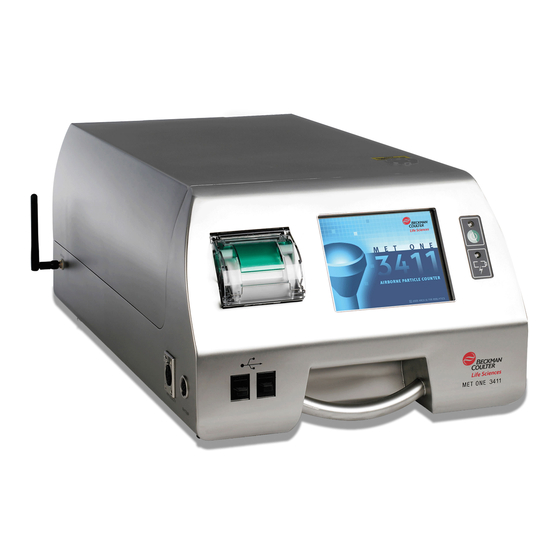
- Page 1 DOC026.53.80359 MET ONE 3411 10/2013, Edition 2, Firmware version 4.08.XX User Manual...
-
Page 3: Table Of Contents
Table of Contents Specifications ....................................7 Instrument specifications ...................................7 Sample measurement specifications ..............................8 Battery specifications ..................................8 General information ..................................8 Safety information ....................................8 Use of hazard information ................................8 Precautionary labels ..................................9 Compliance ....................................9 Certification ......................................9 Wi-Fi devices ....................................10 Country-specific approval for Wi-Fi devices ..........................10 Certification ....................................11 Product overview .....................................11 Product components ..................................11... - Page 4 Table of Contents Setup for Ethernet communication ..............................21 Setup for wireless communication ..............................21 Set wireless security ..................................21 Configuration ....................................21 About configuration ..................................21 About Basic and Advanced operation ..............................21 Set the operation mode at initial startup ...........................21 Change the operation mode ..............................22 Configure the system ..................................22 Set the time and date ................................22 Set the sleep mode and backlight timeout ..........................22...
- Page 5 Table of Contents Location management ................................26 Add a location ..................................26 Edit a location ..................................26 Configure new settings for the location ..........................26 Copy settings from another location ..........................27 Set location alarms ................................27 Remove a location ................................27 Change the order of locations ............................27 Area management ..................................28 Add a new area .................................28 Edit an area ..................................28...
- Page 6 Table of Contents Assign user access rights .................................31 Operation ......................................31 Log on to the particle counter ................................31 Measure particle counts ...................................32 Change the particle count location ............................32 See settings during the particle count ............................32 See historical data during the particle count ..........................32 Use the filter scan probe ................................32 Manage sample batch identification ............................32 Enter or change a Batch ID ...............................32...
- Page 7 Table of Contents Automatic data download .................................38 Calibration .......................................38 Maintenance ....................................38 Clean the instrument exterior ................................39 Set the count to zero ..................................39 Update the instrument software ...............................39 Charge the batteries in the particle counter .............................39 Battery recharge intervals .................................40 Calibrate the battery ..................................40 Diagnostics and Troubleshooting ............................40 Factory settings...
- Page 8 Table of Contents...
-
Page 9: Specifications
Specifications Specification Detail Specifications are subject to change without notice. Outputs Ethernet–10Base-T/100Base-TX RS485 Serial Instrument specifications RS232 Serial Specification Detail Optional wireless–802.11 b/g compatible Power requirement 100–240 VAC, 3.4 A maximum, 50–60 Hz to the AC- USB Client (Version 1.1) to-DC power supply;... -
Page 10: Sample Measurement Specifications
Sample measurement specifications Safety information N O T I C E Sampling The manufacturer is not responsible for any damages due to misapplication or Particle size ranges and 0.1, 0.2, 0.3, 0.5, 1.0, 5.0 µm misuse of this product including, without limitation, direct, incidental and standard channels consequential damages, and disclaims such damages to the full extent permitted under applicable law. -
Page 11: Precautionary Labels
This product complies with IEC/EN 60825-1:2007 and 21 CFR Precautionary labels 1040.10 except for deviations pursuant to Laser Notice No. 50, dated Read all labels and tags attached to the instrument. Personal injury or June 24, 2007. FDA accession number: 8721904-033. damage to the instrument could occur if not observed. -
Page 12: Wi-Fi Devices
1. Disconnect the equipment from its power source to verify that it is or Country ISO31662 letter code is not the source of the interference. France 2. If the equipment is connected to the same outlet as the device experiencing interference, connect the equipment to a different Germany outlet. -
Page 13: Certification
Certification Figure 1 Product components The device complies with Part 15 of the FCC Rules and Industry Canada license-exempt RSS standard(s). Operation is subject to the following conditions: 1. The equipment may not cause harmful interference. 2. The equipment must accept any interference received, including interference that may cause undesired operation. -
Page 14: Installation
Installation Electrical connections Connect probes, external power, cables and USB devices as shown in W A R N I N G Figure 2 Figure Multiple hazards. Only qualified personnel must conduct the tasks Figure 2 Back view described in this section of the document. Wiring safety information W A R N I N G Electrocution hazard. -
Page 15: Lithium Battery Safety
Note: For best results, use USB flash drives supplied by the manufacturer. Figure 3 Front and side view Lithium battery safety W A R N I N G Fire and explosion hazard. Lithium batteries may get hot, explode or ignite and cause serious injury if exposed to abuse conditions. •... - Page 16 14 English...
- Page 17 English 15...
-
Page 18: Assemble The Particle Counter System
Assemble the particle counter system Refer to the illustrated steps in Figure 5 to install printer paper. Figure 4 shows how to assemble the particle counter system. Figure 5 Printer paper installation Figure 4 Particle counter assembly 1 Remote installation of the probe 2 Local installation of the probe Shown with the optional isokinetic probe stand. -
Page 19: Connect To Clean Dry Air (Optional)
Connect to clean dry air (optional) 2. Switch on the particle counter. 3. Switch on the purge air. Make sure that all the components installed before the particle counter, including interconnecting lines, are pressure rated for higher than Connect RS485 communication (optional) 150 psi. - Page 20 18 English...
-
Page 21: Particle Counter Navigation
Particle counter navigation Table 1 Icons - Counter Navigation screen (continued) Icon Function Description The functions of the particle counter are accessed from the Counter Navigation screen. Table 1 shows the functions that are accessible System Time/Date; Sleep time/backlight timeout; set logon through the navigation screen. -
Page 22: Network And Communications
Network and communications Table 2 Icons – general (continued) Icon Function Description N O T I C E Copy the location Makes a copy of the location settings Only qualified personnel should perform the tasks described in this section. settings About network and communications setup Paste the location Saves the copied location settings over the... -
Page 23: Setup For Ethernet Communication
Setup for Ethernet communication • Select the authentication type. • Select the key type: Hex or Passphrase. 1. On the Counter Navigation screen, push NETWORK. • Enter the key in the Key field and in the Retype Key field. 2. Select the Ethernet tab. Configuration 3. -
Page 24: Change The Operation Mode
1. Power on the instrument. Set the sleep mode and backlight timeout 2. While the operation mode selection screen shows, do one of the Sleep mode and backlight time are active during battery use. When the actions that follow: instrument is connected to AC power, sleep mode and backlight are not active. -
Page 25: Set The Sample Comments Option
3. On the Alarm Reasons screen, select REQUIRED, OPTIONAL or Option Description DISABLED. Refer to Table 3 for more information. Optional After each user-initiated sample cycle, the user is asked if Note: The Alarm Reasons option is set to Disabled by default. they would like to enter a comment for the sample. -
Page 26: Set The Measurement Units
3. Select the User Feedback field. Edit an alarm reason 4. Select a sound from the list of available notification sounds. 1. On the Counter Navigation screen, push SYSTEM. 5. Select sounds for stop error, alarm limit and warnings from the list of 2. -
Page 27: Set The Inert Gas And Altitude Values
3. Select the yellow text below Counts to show the Alarm Reasons list. 1. On the Counter Navigation screen, push SYSTEM. Note: The yellow text shows the type of alarm that has been recorded. 2. Select the Units and Alarms tab. 4. -
Page 28: Install A Configuration
3. Insert a USB drive into the USB host connector. Refer to Electrical Location management connections on page 12. Add a location 4. Push COPY CONFIGURATION TO USB. 5. A confirmation message will show. Push OK. 1. On the Counter Navigation screen, push LOCATIONS. 6. -
Page 29: Copy Settings From Another Location
3. Select a location within the area. 4. In the Sample Location Setup screen, push ALARMS. The Alarm Settings screen has two tabs to configure. • Push ADD LOCATION to configure a new location. 5. In the Count tab: • Push EDIT LOCATION to change the configuration of a current location. -
Page 30: Area Management
Area management Group management Add a new area A group is a collection of sample parameters and settings that Use up to 15 alphanumeric characters to name an area. can include locations. The locations in a group do not need to be geographically co-located. -
Page 31: Data Management
5. Navigate to the needed location and select it, then push OK. 4. Push ENTER to confirm. Note: Push the UP or DOWN arrow to change the order of locations in the 5. Push YES to clear the data buffer. Group Settings screen. -
Page 32: Manage Users And Permissions
1. At the particle counter, make a folder to hold the count data. Select 3. Select the Password field. Enter the default password "123456". Date or enter a name for the folder. Push ENTER. 2. Select Configure File Name. 4. Push OK. 3. -
Page 33: Assign Groups To A User
4. Select the User Name field and enter a user name. Option Description 5. Select the Password field and enter a password. Group Settings The user can set up or modify group settings. 6. Select the Confirm Password field and enter the same password. Area/Location The user can set up or modify area and/or location 7. -
Page 34: Measure Particle Counts
Measure particle counts 2. Select the HISTORICAL icon to see the data. Use the filter scan probe N O T I C E After a complete particle count measurement, the number of particles measured will show on the screen and be stored as data. Other The filter scan probe function applies to 1 CFM units only. -
Page 35: Set Or Clear The Batch Id
3. Select BATCH ID. About reports 4. Delete the Batch ID text. ISO 14644-1, FS 209E and BS 5295 specify calculations for airborne particle counter count data. These documents establish the definitions 5. Push ENTER. The default Batch ID value will show, but will not be for level of cleanliness in cleanrooms and clean zones based on reported. -
Page 36: Start Sample Measurement With The Wizard
b. Highlight a location. Use the UP or DOWN arrows to change the order of locations as needed. The order of the list will be the The particle counter has a built-in printer. The Print Center screen order of the test. is accessible from the: 6. -
Page 37: Print Records Manually
4. To show the average of the values in the printout when the samples Figure 6 Averages report are taken and the data is printed, select Print Averages. Note: The fourth value in the printout is the average of the three previous values. -
Page 38: Review Historical Buffer Data
Set the data filter Figure 7 Buffer report (all buffer records) The data filter can be set up to sort by location, date and time, either as individual parameters or in combination. To set the data filter, go to the Data Filter Setup screen. -
Page 39: About Status Values In Exported Data
3. Select PDF, Comma Separated File, Tab Separated File, XML or Table 4 Sample status bit mask definitions (continued) PortAll. Bit Value Definition Bit Value Definition Note: The PDF option shows only after the PDF option has been set to on. Refer to Turn on the PDF option on page 29. -
Page 40: Configure And Enable The Ftp Function
Data transfer to the OPC server Configure and enable the FTP function With firmware V4.08, the particle counter can be configured to transmit Only administrators, factory service personnel and operators with User data via Ethernet (wired or wireless when the wireless option is installed) Upload permission can initiate data upload to the OPC server. -
Page 41: Clean The Instrument Exterior
Update the instrument software C A U T I O N N O T I C E Multiple hazards. Only qualified personnel must conduct the tasks described in this section of the document. Do this procedure with only manufacturer-supplied files and directions. 1. -
Page 42: Battery Recharge Intervals
Diagnostics and Troubleshooting Table 5 Battery LED color indications LED state LED color Battery status Charge status Flashing Orange Low power Not charging The Diagnostics screen shows information that may be needed for troubleshooting. Table 7 shows an example of a failure notification on Flashing Green Low power... -
Page 43: Parts And Accessories
To view the factory information including the calibration date: 3411 parts (continued) Description Quantity Item number 1. Log on as an administrator. 2. On the Counter Navigation screen, push FACTORY. The factory Brush, intake nozzle cleaning 995240 settings show (e.g., calibration date, calibration due date and nominal flow). -
Page 44: Spare Parts Kit (2087919-01)
3411 parts (continued) Description Quantity Item number High pressure diffuser, 28.3 L/min 2080732-13 (1.0 CFM), 3/8-in. barb USB 2.0 high speed, 1 m (3.3 ft) cable 460-400-4798 USB to RS-232 adapter, DB-9 null modem 2088012-02 USB to RS-485 adapter 2088012-01 Use only the manufacturer-supplied USB flash drives. - Page 46 Beckman Coulter, Inc. Beckman Coulter do Brasil Com e Imp de Prod de Lab Ltda 250 S. Kraemer Blvd. Estr dos Romeiros, 220 - Galpao G3 - Km 38.5 Brea, CA 92821, U.S.A. 06501-001 - Sao Paulo - SP – Brasil www.particle.com...
Need help?
Do you have a question about the MET ONE 3411 and is the answer not in the manual?
Questions and answers