Table of Contents
Advertisement
Advertisement
Table of Contents

Related Manuals for Beckman Coulter Optima TLX


Summary of Contents for Beckman Coulter Optima TLX
- Page 1 TLX-IM-9 Optima ™ Preparative Ultracentrifuge Instruction Manual...
- Page 2 Symbol Simbolo Symbol Title Titel Titre Titulo Titolo Symbole Símbolo Dangerous voltage Gefährliche elektrische Spannung Courant haute tension Voltaje peligroso Pericolo: alta tensione Attention, consult accompanying documents Achtung! Begleitpapiere beachten! Attention, consulter les documents joints Atención, consulte los documentos adjuntos Attenzione: consultare le informazioni allegate On (power) Ein (Netzverbindung)
- Page 3 Safety During Installation and/or Maintenance This ultracentrifuge is designed to be installed by a Beckman Coulter Field Service repre- sentative. Installation by anyone other than authorized Beckman Coulter personnel invali- dates any warranty covering the instrument.
- Page 4 Laboratory Biosafety Manual) are handled; materials of a higher group require more than one level of protection. • Dispose of all waste solutions according to appropriate environmental health and safety guidelines. It is your responsibility to decontaminate the centrifuge and accessories before requesting service by Beckman Coulter.
- Page 5 TLX-IM-9 February 2007 © 2007 Beckman Coulter, Inc. Printed in the U.S.A.
-
Page 7: Table Of Contents
Contents Page INTRODUCTION Certification ..........Scope of Manual. - Page 8 OPERATION Summary of Optima TLX Run Procedures ....3-2 Programmed Run ........3-2 Manual Run .
- Page 9 Page Figure 1-1. The Optima TLX Ultracentrifuge......1-1 Figure 1-2. Temperature Control Diagram ......1-3 Figure 1-3.
-
Page 10: Introduction
Declarations of conformity and certificates of compliance are available at www.beckmancoulter.com. SCOPE OF MANUAL This manual is designed to familiarize you with the Beckman Coulter Optima™ TLX ultracentrifuge, its functions, specifications, opera- tion, and routine operator care and maintenance. We recommend that... -
Page 11: Conventions
Introduction NOTE If the ultracentrifuge is used in a manner other than specified in this manual, the safety and performance of this equipment could be impaired. Further, the use of any equipment other than that recommended by Beckman Coulter has not been evaluated for safety. Use of any equipment not specifically recommended in this manual and/or the applicable rotor manual is the sole responsibility of the user. -
Page 12: Typographic Conventions
] key is not in capitals.) • Display names (for example, SPEED rpm or TIME hr:min) appear in bold type. CFC-FREE CENTRIFUGATION To ensure minimal environmental impact, no CFCs are used in the manufacture or operation of the Optima TLX ultracentrifuge. -
Page 13: Radio Interference
For Beckman Coulter products bearing this label please contact your dealer or local Beckman Coulter office for details on the take back program that will facilitate the proper collection, treatment,... -
Page 14: Description
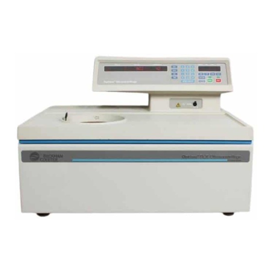
Description DESCRIPTION The Optima TLX (see Figure 1-1) microprocessor-controlled tabletop ultracentrifuge generates high centrifugal forces for a variety of high- speed applications. The instrument design features a variable-fre- quency induction drive, thermoelectric temperature control system, self-purging vacuum system, rotor overspeed identification system, program memory that can contain up to ten five-step programs, and... -
Page 15: Rotor Chamber
Description Manual and programmed operation are available. • In manual operation, you enter the individual run parameters before beginning each run. • In programmed operation, you can duplicate runs quickly and accurately by selecting one of ten programs previously entered into the program memory. -
Page 16: Temperature Sensing And Control
Description TEMPERATURE SENSING AND CONTROL The solid-state thermoelectric temperature control system uses only forced air—no coolant is required. With the power on, the tempera- ture control system is activated when the door is closed and the vacuum system comes on. Run temperature can be set between 0 and 40°C. -
Page 17: Controls And Indicators
Description CONTROLS AND INDICATORS POWER SWITCH The power switch controls electrical power to the ultracentrifuge. It is also a circuit breaker that will trip to cut off power in the event of a power overload. The power switch must be turned on before the chamber door can be opened. - Page 18 Description Digital Displays SPEED rpm TIME hr:min TEMPERATURE°C PROGRAM STEP ACCEL DECEL The displays serve a dual purpose. • During a run, they show the actual (real-time) operating conditions. • When the run parameters are being entered, they show the set values selected.
- Page 19 Description STEP • During setup—when the [ ] key is pressed a dash flashes in STEP this display, indicating which step is being created or modified. • During centrifugation— the number of the step being run is displayed. ACCEL When the [ ] key is pressed, a dash flashing in the display indi- ACCEL cates that an acceleration rate can be entered.
- Page 20 Description Pressed to enter run temperature (using the keypad), from 0 to 40°C. TEMP If a new temperature is not entered, the instrument automatically uses the last temperature entered. (Default temperature for a new ultracen- trifuge is 25°C.) Keypad The keypad is used to enter numerical run parameters, to enter or recall a program number, and to select acceleration and/or decelera- tion rates.
-
Page 21: Safety Features
The double keys are designed to help prevent accidental deletion of a program. SAFETY FEATURES The Optima TLX ultracentrifuge has been designed and tested to operate safely indoors at altitudes up to 2 000 m (6 562 ft). DOOR The steel chamber door has an electromechanical door-locking mech- anism to prevent operator contact with a spinning rotor. -
Page 22: Barrier Ring
SPD will appear. NAME RATING PLATE A name rating plate is affixed to the rear of the instrument. Always mention the serial number and model number when contacting Beckman Coulter regarding your Optima TLX ultracentrifuge. -
Page 23: Specifications
Description SPECIFICATIONS Only values with tolerances or limits are guaranteed data. Values without tolerances are informative data, without guarantee. Speed Set speed ... 5 000 to 120 000 rpm in 1 000-rpm increments Speed control . -
Page 24: Available Rotors
Description AVAILABLE ROTORS All Beckman Coulter TL-series rotors can be used in the Optima TLX ultracentrifuge (see Table 1-1). The rotors are described in individual manuals that accompany each rotor. Information on rotors and accessories is also available in Rotors and Tubes for Tabletop Preparative Ultracentrifuges (TLR-IM, available on CD 369668) and in the Ultracentrifuge Rotors, Tubes &... - Page 25 Description Table 1-1. Available Rotors (continued) Number of Max RCF † Tubes × Rotor (x g) Max RPM/ Nominal Manual at r Rotor Profile and Description k factor* Capacity Number TLA-100.3 100 000 543 000 6 × 3.5 mL TL-TB-011 Fixed Angle 30°...
- Page 26 Description Table 1-1. Available Rotors (continued) Number of Max RCF † Tubes × Rotor (x g) Max RPM/ Nominal Manual at r Rotor Profile and Description k factor* Capacity Number 45 000 125 000 12 × 1.5 mL TL-TB-012 TLA-45 ‡...
-
Page 27: Preinstallation Requirements
TLX ultracentrifuge. The following information is included in case the instrument must be relocated. NOTE This ultracentrifuge is designed to be installed by a Beckman Coulter Field Service representa- tive. Installation by anyone other than autho- rized Beckman Coulter personnel invalidates any warranty covering the instrument. -
Page 28: Electrical Requirements
23.0 73.7 29.0 Figure 2-1. Dimensions of the Optima TLX Ultracentrifuge ELECTRICAL REQUIREMENTS 100-V centrifuge ....90–110 VAC, 12 A, 50/60 Hz 120-V centrifuge ....100–130 VAC, 12 A, 50/60 Hz... - Page 29 (A plug that meets your local electrical and safety requirements was supplied with the instrument. Contact your local Beckman Coulter office for specific information regarding local requirements.) To preserve this safety feature: • Make sure that the matching wall outlet receptacle is properly wired and earth-grounded.
- Page 30 Operation This section contains manual and programmed operating proce- dures. A summary is provided at the start of this section. If you are an experienced user of this ultracentrifuge, you can turn to the summary for a quick review of operating steps. WARNING Normal operation may involve the use of solu- tions and test samples that are pathogenic,...
-
Page 31: Operation
Do not lean on the instrument or place items on it while it is operating. SUMMARY OF OPTIMA TLX RUN PROCEDURES For runs at other than room temperature, refrigerate or warm the rotor beforehand for fast equilibration. For low-temperature runs, precool the system as described under Pre-Run Cooling or Warming, below. -
Page 32: Manual Run
Operation MANUAL RUN POWER Turn the POWER switch to ON ( I ). Press [ ] to unlock the chamber door; slide the door open. DOOR DOOR Install the rotor according to the applicable rotor manual. Be sure to lock it in place by pressing the plunger down until you hear a click. -
Page 33: Installing The Rotor
Operation INSTALLING THE ROTOR The power must always be turned on before you can unlock and open the chamber door. Action Result 1. Turn the POWER switch on. Indicator lights on the control panel light up. (To end a run for any reason, do not turn the POWER switch off;... -
Page 34: Pre-Run Cooling Or Warming
Operation Action Result 5. Close the chamber door. (To keep the chamber clean and dry, leave the door closed whenever possible.) PRE-RUN COOLING OR WARMING For fast temperature equilibration, cool or warm the rotor to the required temperature before the run. Also precool or warm the instru- ment as follows. -
Page 35: Manual Operation
Operation Action Result 5. Press [ The SPEED rpm display flashes. SPEED 6. Use the keypad to enter A 0 appears on the SPEED rpm display. 0 rpm. 7. Press [ ] and The instrument will begin cooling. ENTER/DISPLAY START MANUAL OPERATION When a run-parameter key is pressed, the appropriate display flashes to indicate that a value can be entered. -
Page 36: Entering Run Time
Operation You can change the set speed at any time by repeating steps 1 through 3. The rotor will accelerate or decelerate to the new speed. ➠ NOTE At 1000 rpm, the instrument identifies the rotor and checks its maximum allowable speed. If set speed is greater than the rotor’s maximum allowable speed, the SPEED rpm display will flash rapidly and the rotor will decelerate to a... -
Page 37: Entering Run Temperature
Operation ENTERING RUN TEMPERATURE Run temperature can be set from 2 to 40°C. If no value is entered, the instrument automatically selects the last entered temperature. (If all previous entries have been cleared, 25°C is selected as the operating temperature.) Action Result 1. - Page 38 Operation Table 3-1. Acceleration and Deceleration Rates ACCEL Time from DECEL Time from Keypad 0 to 5000 rpm 5000 to 0 rpm Number (minutes) (minutes) (blank) coasting stop from set speed without brake *Maximum rate. If no keypad number is selected, the rotor will accelerate and/or decelerate at maximum rates.
-
Page 39: Starting A Run
Operation STARTING A RUN Action Result 1. Press [ ] and The green light above the [ ] key flashes and the rotor begins ENTER/DISPLAY START to spin. START ➠ NOTE To begin a run, [ ] must always be ENTER/DISPLAY the last key pressed before pressing [ START... -
Page 40: Programmed Operation
Operation PROGRAMMED OPERATION The instrument internal memory can store up to ten programs which can be recalled by keypad numbers 0 through 9. Each program can contain up to five steps (that is, up to five sets of run parameters). Programs are retained in memory even if the power is turned off. -
Page 41: Starting A Programmed Run
Operation STARTING A PROGRAMMED RUN Action Result 1. Press [ A dash flashes in the PROGRAM display. PROG 2. Use the keypad to enter the The number you selected will appear in the PROGRAM display; a 1 number of the program. (indicating step 1) will appear in the STEP display. -
Page 42: Recalling, Changing, Or Deleting A Program
Operation Action Result 5. After the rotor has stopped, The door is unlocked and the chamber vented. press [ DOOR 6. Remove the rotor. Keep the chamber door closed between runs. RECALLING, CHANGING, OR DELETING A PROGRAM Recalling a Program A program that has been saved in memory can be recalled at any time. - Page 43 Operation Action Result 2. Press [ ] repeatedly until Run parameters for the designated step are displayed for 5 seconds. STEP the number of the selected step is displayed. 3. Press the run parameter key The PROGRAM display and the associated parameter display flash. to be changed.
-
Page 44: Troubleshooting
] to clear the message.) An intermittent tone will sound for 10 seconds to alert you that a shutdown has occurred. Refer to Table 4-1 to determine the nature of the condition and any recom- mended actions. If the problem persists, contact Beckman Coulter Field Service for assistance. -
Page 45: Figure 4-1. Location Of User Messages On The Control Panel
(In case of program memory loss, the instrument is still functional Deceleration without for manual operation.) Call Beckman Coulter Field Service. brake Loss of power during A power outage has occurred during the run. If power is restored while the... - Page 46 • rotor load is within limits; • magnets on the rotor bottom are undamaged. Press to clear the message. If message persists, call Beckman Coulter Field Service. Loss of chamber This message appears any time the door is open or the chamber pressure is above vacuum/Decelera- 500 microns.
-
Page 47: Retrieving Your Sample In Case Of Power Failure
Troubleshooting RETRIEVING YOUR SAMPLE IN CASE OF POWER FAILURE If facility power fails only momentarily, the instrument will resume operation when power is restored and the rotor will return to set speed. However, if the rotor came to a complete stop, you will have to restart the run when the power is restored. -
Page 48: Figure 4-2. Removing The Top Cover Of The Instrument
Troubleshooting Door Handle Instrument Cover Figure 4-2. Removing the Top Cover of the Instrument Action Result CAUTION 3. Remove three screws on each LISTEN CAREFULLY. Do not proceed if any side of the top instrument sound or vibration is coming from the drive. cover and slide the panel housing toward you to remove it. -
Page 49: Figure 4-3. Door Lock System
Troubleshooting Spring-loaded Pin Hole in Chamber Plate Door Lock System Screw Vacuum Solenoid Figure 4-3. Door Lock System Action Result 6. Insert a screwdriver or simi- If the rotor is still spinning, close the door and wait. The drive is very lar tool into the small hole in quiet and may emit no audible sounds below 10 000 rpm. -
Page 50: Circuit Breaker
Troubleshooting Action Result 7. After removing the rotor, replace the top panel and door handle by following the instructions above in reverse order. CIRCUIT BREAKER If the circuit breaker on the instrument trips repeatedly, call Beckman Coulter Field Service for assistance. -
Page 51: Maintenance
This section contains care and maintenance procedures that should be performed regularly. For maintenance not covered in this manual, contact Beckman Coulter Field Service (1-800-742-2345 in the United States; worldwide offices are listed on the back of this man- ual) for assistance. User messages and recommended actions are discussed in Section 4, TROUBLESHOOTING. -
Page 52: Vacuum System
1. Leave the instrument turned on with the door closed for about 3 hours or, if convenient, overnight. 2. Call your Beckman Coulter Field Service representative to change the vacuum oil if it remains contaminated. (The instrument will continue to display a VAC message after following the instruction... -
Page 53: Drive Hub
Refer to the chemical resistances list in Appendix A of Rotors and Tubes, or contact Beckman Coulter Field Service to ensure that the decontami- nation method does not damage any part of the instrument (or... -
Page 54: Sterilization And Disinfection
While Beckman Coulter has tested these methods and found that they do not damage the instrument, no guarantee of sterility or disinfection is expressed or implied. When sterilization or disinfection is a concern, consult your laboratory safety officer regarding proper... -
Page 55: Supply List
Maintenance SUPPLY LIST Contact Beckman Coulter Sales (1-800-742-2345 in the United States; worldwide offices are listed on the back of this manual) for information about ordering parts and supplies. A partial list of supplies is given below for your convenience. See the Ultracentrifuge Rotors, Tubes &... - Page 56 Beckman Coulter, or period of time, Beckman Coulter will repair or, at its election, unless such repair in the sole opinion of Beckman Coulter is replace such component or accessory.
- Page 57 Telephone: (27) 11-805-2014/5 Fax: (27) 11-805-4120 e-mail: beckman@intekom.co.za Beckman Coulter, Inc. • 4300 N. Harbor Boulevard, Box 3100 • Fullerton, California 92834-3100 Sales and Service: 1-800-742-2345 • Internet: www.beckmancoulter.com • Telex: 678413 • Fax: 1-800-643-4366 ©2007 Beckman Coulter, Inc. Printed on recycled paper...
Need help?
Do you have a question about the Optima TLX and is the answer not in the manual?
Questions and answers