
Related Manuals for Beckman Coulter Optima MAX-XP


Summary of Contents for Beckman Coulter Optima MAX-XP
- Page 1 Instructions For Use Optima MAX-XP Ultracentrifuge 393552AH August 2018 Beckman Coulter, Inc. 250 S. Kraemer Blvd. Brea, CA 92821 U.S.A.
- Page 2 Ultracentrifuge 393552AH (August 2018) © 2018 Beckman Coulter, Inc. Beckman Coulter, the stylized logo, and the Beckman Coulter product and service marks mentioned herein are trademarks or registered trademarks of Beckman Coulter, Inc. in the United States and other countries.
-
Page 3: Revision History
Revision History Your Biomek i-Series documentation can be found on our website. For updates, go to www.beckman.com/techdocs and download the latest version of the manual or system help for your instrument. - Changes or additions were made to:Multiple Compliance. Revision AG, 04/2017 - Changes or additions were made to: CHAPTER 4, User Message Chart;... - Page 4 Revision History 393552AH...
-
Page 5: Safety Notice
NOTE is used to call attention to notable information that should be followed during installation, use, or servicing of this equipment. Safety During Installation and/or Maintenance This ultracentrifuge is designed to be installed by a Beckman Coulter Field Service representative. Installation by anyone other than authorized Beckman Coulter personnel invalidates any warranty covering the ultracentrifuge. -
Page 6: Electrical Safety
Safety Notice Electrical Safety Electrical Safety To reduce the risk of electrical shock, this equipment uses a three-wire electrical cord and plug to connect the ultracentrifuge to earth-ground. To preserve this safety feature: • Make sure that the matching wall outlet receptacle is properly wired and earth-grounded. Check that the line voltage agrees with the voltage listed on the name-rating plate affixed to the ultracentrifuge. -
Page 7: Chemical And Biological Safety
Beckman Coulter Field Service. Summary of Instrument Labels This section provides information for some labels and symbols appearing on the Optima MAX-XP instrument housing. These labels and symbols may be associated with user-serviceable procedures. Individual hazards associated with a specific procedure in this manual may use these labels and symbols, and are included in Warnings or Cautions within the procedures for that task. - Page 8 For Beckman Coulter products bearing this label, please contact your dealer or local Beckman Coulter office for details on the take-back program that will facilitate the proper collection, treatment, recovery, recycling and safe disposal of the device.
- Page 9 For details on proper grounding, see IEEE standard P1100. DANGER High Voltage Operation, replacement or servicing of any components where contact with bare, live hazardous parts could occur, possibly resulting in electric shock, should only be performed by your Beckman Coulter representative. 393552AH...
- Page 10 Safety Notice Summary of Instrument Labels Protective Ground This symbol is used to indicate a protective ground. This instrument must be properly grounded. Do not under any circumstances operate the instrument unless it is properly grounded. WARNING Risk of Fire Before replacing fuses, shut off power and disconnect the power cord.
- Page 11 This symbol indicates that the instrument has been configured for operation at 240 VAC. Consult with a Beckman Coulter service engineer for use at other line voltages. NOTICE Regarding Vacuum Pump Oil This label indicates to use only ULVAC R2 rotary vacuum pump oil (Beckman Coulter part number A51210). 393552AH...
- Page 12 Safety Notice Summary of Instrument Labels Rotor Rotation This indicates the direction of instrument rotor rotation. SER NO (Serial Number) SER NO This label indicates the location of the instrument serial number. 393552AH...
-
Page 13: Table Of Contents
Contents Revision History, iii Safety Notice, v Alerts for Danger, Warning, Caution, and Note, v Safety During Installation and/or Maintenance, v Electrical Safety, vi Safety Against Risk of Fire, vi Mechanical Safety, vi Chemical and Biological Safety, vii Summary of Instrument Labels, vii Introduction, xix Certification, xix... -
Page 14: Introduction
Space Requirements, 2-1 Electrical Requirements, 2-2 CHAPTER 3: Introduction, 3-1 Touchscreen Interface, 3-1 Modes of Operation, 3-2 Summary of Optima MAX-XP Run Procedures, 3-3 Ultracentrifuge and Rotor Preparation, 3-3 Manual Run, 3-4 Programmed Run, 3-5 Manual Operation, 3-6 Preparing the... - Page 15 Drive Hub, 5-2 Air-Intake and Exhaust Louvers, 5-2 Cleaning, 5-2 Ultracentrifuge Surfaces, 5-2 Touchscreen Display, 5-2 Decontamination, 5-3 Sterilization and Disinfection, 5-3 Storage and Transportation, 5-3 Supply List, 5-3 Supplies, 5-4 Optional Accessories, 5-4 Warranty for the Optima MAX-XP Ultracentrifuge...
- Page 16 Illustrations The Optima MAX-XP Ultracentrifuge, 1-1 Temperature Control Diagram, 1-3 Touchscreen Interface, 1-4 Dimensions of the Optima MAX-XP Ultracentrifuge, 2-2 Touchscreen Interface Main Screen, 3-2 Example User Message on Touchscreen Interface, 4-2 Removing the Top Cover of the Ultracentrifuge, 4-7...
- Page 17 Tables Tables Acceleration and Deceleration Rates, 3-17 User Message Chart, 4-2 xvii...
- Page 18 Tables xviii...
-
Page 19: Certification
Declarations of conformity and certificates of compliance are available at www.beckmancoulter.com. Scope of Manual This manual is designed to acquaint you with the Optima MAX-XP Ultracentrifuge, its functions, specifications, operation, and routine operator care and maintenance. We recommend that you read this entire manual, especially the... -
Page 20: Typographic Conventions
CFC-Free Centrifugation To ensure minimal environmental impact, no CFCs are used in the manufacture or operation of the Optima MAX-XP Ultracentrifuge. Radio Interference This equipment has been tested and found to comply with the limits for a Class A digital device, pursuant to Part 15 of FCC rules. -
Page 21: Description
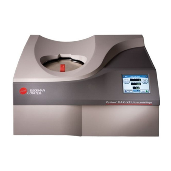
Figure 1.1 The Optima MAX-XP Ultracentrifuge Intended Use Use the Optima MAX-XP Ultracentrifuge for applications requiring high force fields that are capable of separating and isolating small particles (virus, bacteria, and subcellular components like mitochondria) and large molecules (peptides, DNA, proteins). These samples are derived from a variety of natural and synthesized components. -
Page 22: Rotor Chamber
Description Temperature Sensing and Control Rotor Chamber The steel chamber is coated with a chemical-resistant finish to resist corrosion. The rotor drive hub and speed sensors are visible in the bottom of the chamber. Vacuum System A diffusion pump, in series with a mechanical vacuum pump, reduces chamber pressure to below 10 microns (1.34 Pa). -
Page 23: Drive
Description Drive Figure 1.2 Temperature Control Diagram +2° °C -2° 1. Actual rotor temperature 3. Time 2. 0.1° (peak-to-peak fluctuation 4. Set Temperature Drive The air-cooled, direct-drive induction motor is frequency controlled, with no gears or brushes. In addition, the drive does not require an oil vacuum seal or external oil reservoir. It is externally cooled by forced air and internally cooled by oil. -
Page 24: Touchscreen Interface
Description Controls and Indicators Figure 1.3 Touchscreen Interface 1. Windshield 5. Login Button 2. Screen Instructions 6. Buttons and Display Fields 3. Help Button 7. Menu Button 4. Set Values The buttons and display fields on the Main screen are described briefly below. For complete information and instructions on using the touchscreen interface, see CHAPTER 3, Operation. - Page 25 Description Controls and Indicators — Displays a list of programmed runs and provides an interface from which to set up • Program new programs. • — Opens the screen. If no user with Administrator privileges is Admin Administrator Options logged in, opens the screen.
-
Page 26: Safety Features
START STOP Safety Features The Optima MAX-XP ultracentrifuge has been designed and tested to operate safely indoors at altitudes up to 2000 m (6562 ft). Ultracentrifuge safety features are described below. Door The steel chamber door has an electromechanical door-locking mechanism to prevent operator contact with a spinning rotor. -
Page 27: Overspeed And Rotor Identification System
Name Rating Plate A name rating plate is affixed to the rear of the ultracentrifuge. When contacting Beckman Coulter regarding your ultracentrifuge, always mention the serial number and model number. You can also... -
Page 28: Physical Data
Description Specifications Specifications Description • Set temperature: Temperature — 0 to 40°C in 1° increments • Temperature control (after equilibration): — ±2°C of set temperature • Temperature display: — actual rotor temperature in 0.1° increments • Ambient temperature range: — 15 to 35°C Acceleration 10 acceleration profiles •... -
Page 29: Available Rotors
Available Rotors All Beckman Coulter ML- and TL-series rotors can be used in the Optima MAX-XP ultracentrifuge. The rotors are described in individual manuals that accompany each rotor. Information on rotors and accessories is also available in Rotors and Tubes for Tabletop Preparative Ultracentrifuges (TLR-IM) and in the Beckman Coulter Ultracentrifuge Rotors, Tubes &... - Page 30 Description Available Rotors Number of Rotor Tubes × Nominal Max RCF (× g) Max RPM/ Manual at r Rotor Profile Description k factor Capacity Number 10 × 2.0 mL TLA-120.2 120,000 627,000 TL-TB-016 Fixed Angle 30° Angle 14 × 0.5 mL TLA-120.1 120,000 627,000...
- Page 31 Description Available Rotors Number of Rotor Tubes × Nominal Max RCF (× g) Max RPM/ Manual at r Rotor Profile Description k factor Capacity Number 20 × 0.2 mL TLA-100 100,000 436,000 TL-TB-003 Fixed Angle 30° Angle 8 × 2.0 mL TLV-100 100,000 400,000...
- Page 32 Maximum speeds are based on a solution density of 1.7 g/mL for all rotors, except the MLS-50, MLA-50, MLA-55, and MLA-80; solution density for these rotors is 1.2 g/mL. The k factors are listed for all Beckman Coulter rotors (using the largest-volume tube) as a measure of the rotor’s relative pelleting efficiency.
-
Page 33: Space Requirements
Preinstallation requirements have been provided for your Optima MAX-XP ultracentrifuge. The following information is included in case the ultracentrifuge must be relocated. NOTE This ultracentrifuge is designed to be installed by Beckman Coulter Field Service. Installation by anyone other than authorized Beckman Coulter personnel invalidates any warranty covering the ultracentrifuge. -
Page 34: Electrical Requirements
IEC 320/CEE-20 AC power connector at the rear of the ultracentrifuge and a plug to connect to earth-ground. (A plug that meets your local electrical and safety requirements was supplied with the ultracentrifuge. Contact your local Beckman Coulter office for specific information regarding local requirements.) To preserve this safety feature: •... - Page 35 Preinstallation Requirements Electrical Requirements • If there is any question about voltage, have a qualified service person measure it under load while the drive is operating. To ensure optimal safety, the ultracentrifuge should be wired to a remote emergency switch (preferably outside the room where the ultracentrifuge is housed, or adjacent to the exit from that room).
- Page 36 Preinstallation Requirements Electrical Requirements 393552AH...
-
Page 37: Chapter 3: Introduction
CHAPTER 3 Operation Introduction This section contains manual and programmed operating procedures. A summary is provided at the start of this section for experienced users. WARNING Normal operation may involve the use of solutions and test samples that are pathogenic, toxic, or radioactive. Handle body fluids with care because they can transmit disease. -
Page 38: Modes Of Operation
Operation Touchscreen Interface You may configure the ultracentrifuge touchscreen for user interaction with different languages. Set Interface Language. Use your fingertip to press the buttons on the touchscreen. A short beep sounds each time you press a button on the touchscreen (unless the audio volume has been muted by your administrator). -
Page 39: Summary Of Optima Max-Xp Run Procedures
Operation Summary of Optima MAX-XP Run Procedures Diagnostics/User Messages When a condition arises that requires operator attention, the windshield turns red. Press the windshield to open a dialog showing the diagnostic message. User messages communicate information about the ultracentrifuge or alert you to an abnormal condition. For more information, CHAPTER 4, Troubleshooting. -
Page 40: Manual Run
Operation Summary of Optima MAX-XP Run Procedures Install the rotor according to the directions in the rotor manual. a. Ensure that the rotor is seated on the drive hub. Close the chamber door. a. To keep the chamber clean and dry, leave the door closed whenever possible. -
Page 41: Programmed Run
Operation Summary of Optima MAX-XP Run Procedures Press the button, then choose the rotor (listed by type and serial number) from the ROTOR rotor list. • This step is optional. a. If you don’t want to select a rotor, go to Step 4. -
Page 42: Manual Operation
Operation Manual Operation Press the button to load the program parameters. Press the button to start the run. START Manual Operation This section includes detailed procedures for entering run parameters for manual operation. Preparing the Ultracentrifuge In the first step of a manual run, install the rotor and perform any precooling or prewarming procedures that may be required. -
Page 43: Selecting A Rotor
Operation Manual Operation Select your user name, enter your PIN on the keypad, and press to accept. • The Main screen returns to view. • If you were required to log in, the run starts. Selecting a Rotor There are two reasons for selecting a rotor: •... -
Page 44: Entering Run Speed
Operation Manual Operation Select the desired rotor, and press the button to accept. • The Main screen returns to view, and the selected rotor name and serial number appear on button. ROTOR a. If you were about to start a run and were required to select a rotor, the run starts automatically when the Main screen returns to view. -
Page 45: Entering Run Time
Operation Manual Operation On the Main screen, press the button. SPEED • The screen appears. Enter Run Speed • The acceptable values for speed are shown above the display field: from 5000 to 150,000 RPM. If a rotor is selected, the display will show the speed range for that rotor. •... -
Page 46: Time,
Operation Manual Operation • In Delayed run mode, the time display first shows the remaining delay time. When the delay has concluded, the run starts and the time display counts down as in Timed mode. Timed Mode Run time can be set for up to 99 hours and 59 minutes. If no new run time is entered, the ultracentrifuge automatically selects the last entered run time. - Page 47 Operation Manual Operation Hold Mode In Hold mode, the run continues until you stop the run by pressing the button. STOP NOTE During Hold mode, the time display starts at zero and continues counting up until you stop the run. If the count reaches 99:59, it resets to 0.
- Page 48 Operation Manual Operation To cancel Hold mode, repeat steps 1–3. • The button turns gray in the screen. HOLD Enter Run Duration disappears from above the Display on the Main screen. — HOLD Time Setting Up a Delayed Run You can set up a run that starts or stops in the future. On the Main screen, press the button.
- Page 49 Operation Manual Operation To set a delayed run to start on a particular date and/or time, press the button. START AT • The fields become active so you can change them. Date Time To set a delayed run to stop on a particular date and/or time, press the button.
- Page 50 Operation Manual Operation Press the button to accept. • The Main screen returns to view, and the set duration of the delayed run appears above the display. Time Press the button. START • The Main screen indicates that a delayed run is in progress. •...
-
Page 51: Entering Run Temperature
Operation Manual Operation To manually stop the delayed run at any time, press the button. STOP • Any time a run is stopping, it is indicated on the Main screen. To cancel the delayed run: a. Press the button in the Main screen. TIME b. -
Page 52: Entering Acceleration And Deceleration Rates
Operation Manual Operation On the Main screen, press the button. TEMP • The screen appears. Enter Run Temperature • The acceptable values for run temperature are shown above the display field: from 0 to 40°C. Enter the temperature on the keypad, and press the button to accept. - Page 53 Operation Manual Operation Table 3.1 Acceleration and Deceleration Rates Touchscreen ACCEL Time DECEL Time Number from 0 to 5000 RPM (MM:SS) from 5000 to 0 RPM (MM:SS) 0:15 0:15 0:30 1:00 1:00 1:30 1:30 2:00 2:00 2:30 2:30 3:00 3:00 4:00 3:30 6:00...
- Page 54 Operation Manual Operation Select Accel/Decel • The screen appears. Select Accel/Decel Rates — The default value for both is Max (maximum speed). Press the desired rate(s) by pressing the appropriate number on the sliders. • The time duration for the rate you select is displayed in the fields on the right. —...
-
Page 55: Starting A Run
Operation Manual Operation Press the button to accept. • If either rate is set to anything other than Max, buttons appear on the ACCEL DECEL Main screen showing the selected rates. Starting a Run On the Main screen, press the button. -
Page 56: Stopping A Run
Operation Manual Operation a. If you are not logged in and has been turned on by the Administrator, you are User Login required to log in. • For more information, see Logging b. If you start a run without selecting a rotor and a message appears asking you to select a rotor, press in the message box. -
Page 57: Viewing A Previous Run
Operation Manual Operation Viewing a Previous Run Viewing a previous run allows access to previous set and actual run information. On the Main screen, press the button. MENU • The list of menu options appears. Select History • A list of previous runs is displayed. If necessary, use the arrows to bring additional runs into view. -
Page 58: Changing The Login Button Design
Operation Manual Operation To view the details of the selected run, press the button. VIEW DETAILS • The screen appears and displays complete information on the run. History Details a. Use the large arrows to bring more details into view. •... -
Page 59: Programmed Operation
Operation Programmed Operation On the Main screen, press the button, and select MENU My Options • The screen appears. Choose Button Type Press the button design that corresponds to the design you want, and press the button to accept. • The Main screen returns to view, and the new button design is displayed until you log out. •... -
Page 60: Creating A New Program
Operation Programmed Operation Creating a New Program In the Main screen, press the button. MENU • The list of menu options appears. Select Program. • The m screen appears. Select Progra • If no programs have been created and saved, the screen will be blank. 3-24 393552AH... -
Page 61: Program,
Operation Programmed Operation Press the button. NEW PROGRAM • The screen appears. Program Summary Select a rotor first. • The rotor you select will determine the available speed settings. a. Press the button. ROTOR • The screen appears. Choose Rotor 3-25 393552AH... - Page 62 Operation Programmed Operation Select the desired rotor, and press the button to accept. • The name of the selected rotor displays on the screen. Program Summary Press the button. NEW STEP • The screen appears. Enter Step Speed • The acceptable values for run speed are shown above the display field: from 5000 to 150,000 RPM, depending on the selected rotor.
- Page 63 Operation Programmed Operation Enter the speed on the keypad display, and press the button to accept. • The screen appears. Enter Step Duration • The acceptable values for run duration are shown above the display field: from 00:01 to 99:59 HH:MM. Enter the run time on the keypad display, and press the button to accept.
- Page 64 Operation Programmed Operation Enter the temperature on the keypad display, and press the button to accept. • The screen appears and displays the parameters for the first step. Program Summary • If you enter a number greater than 40, the button will be grayed out.
- Page 65 Operation Programmed Operation To change the acceleration/deceleration rates, press either the button. ACCEL DECEL • The screen appears. Select Accel/Decel Rates a. To use the maximum values for both rates, go to Step 12. • Note that the default rates of “ ”...
- Page 66 Operation Programmed Operation Press the button to accept. • The rates you select display on the screen. Program Summary Press the button to accept. • The screen appears. Enter Program Name Type the name of the program using the keypad just as you would a keyboard. •...
-
Page 67: Starting A Programmed Run
Operation Programmed Operation a. Note that the key is green to indicate that uppercase letters are the default. SHIFT • To enter lowercase letters, press the key. SHIFT b. Press to erase entered characters ne at a time. BACKSPACE c. To clear the entire entry, press CLEAR Press the button to accept. - Page 68 Operation Programmed Operation Select Program • The screen appears. Select Program NOTE is highlighted in this list, it means that no saved program is currently No Program Selected selected. Select the name of the program you want to run, and press the button.
- Page 69 Operation Programmed Operation Press the button. START • The Main screen reflects the start of the run. • This screen updates continuously to reflect the progress of each step in the program. a. If you are not logged in and has been turned on by the Administrator, you are User Login required to log in.
-
Page 70: Making Changes To A Program
Operation Programmed Operation To exit from program mode: a. Press the button in the Main screen. MENU b. In the screen, select Select Program No Program Selected c. Press • The Main screen returns to view so that you can enter parameters manually. d. - Page 71 Operation Programmed Operation Select Program • The screen appears. Select Program a. If necessary, use the arrows to bring additional program names into view. Select the name of the program you want to modify. • The name of the program is highlighted, and the button becomes available.
- Page 72 Operation Programmed Operation Press the button. EDIT PROGRAM • The screen displays the steps and other parameters of the selected Program Summary program. You can do any of the following: a. To delete a step, select the desired step and press the button.
-
Page 73: Deleting A Program
Operation Programmed Operation Deleting a Program In the Main screen, press the button. MENU • The list of menu options appears. Select Program • The screen appears. Select Program Select the name of the program you want to delete. If necessary, use the arrows to bring additional program names into view. •... -
Page 74: Pulse Run Operation
Operation Pulse Run Operation To delete the program, press the button. DELETE PROGRAM • A confirmation message appears. Press the button. • The program is deleted and removed from the list of saved programs. Pulse Run Operation Set up the ultracentrifuge as described in Preparing the Ultracentrifuge. - Page 75 Operation Pulse Run Operation Select Pulse • The button becomes available on the Main screen. PULSE To start the run, press and hold down the button. PULSE • The Pulse run starts. — The windshield in the Main screen turns green and reads Pulsing a.
-
Page 76: Remote Operation
Operation Remote Operation Remote Operation The Optima MAX-XP ultracentrifuge can be operated from a remote computer using the software and hardware provided in Remote Control Kit 393395. For information on ordering this kit, contact Beckman Coulter. Administrator Operations This section describes the procedures performed by the Administrator. The Administrator... -
Page 77: Set Interface Language
Operation Administrator Operations You can do the following from this screen: • Set the audio volume. — See Setting Audio Volume. • Set the interface language. — See Set Interface Language. • Set the date and time. — See Setting the Date and Time. - Page 78 Operation Administrator Operations On the Main screen, press the button, and select MENU Admin • The screen appears. Administrator Options Press the button. LANGUAGE • The screen appears. Language Settings Press a language from the language options list. NOTE Select either the Up or Down arrow keys to view the full list of available languages. 3-42 393552AH...
-
Page 79: Setting The Date And Time
Operation Administrator Operations Press • A screen appears and prompts you to restart the system. Pres • The system restarts and displays the selected language. Setting the Date and Time Go to the Administrator Options screen as described in Accessing Administrator Options. -
Page 80: Adding And Managing Users
Operation Administrator Operations Press either to configure the system to display time in either 12- or 24-hour 12 hr 24 hr format. a. Press the button to accept. • Time and date configurations are set, and the screen returns to view. Administrator Options Adding and Managing Users Adding a User... - Page 81 Operation Administrator Operations Enter a user name on the keypad. a. When finished, press the button to accept. • The # screen appears. Enter PIN Note that the key is green to indicate that uppercase letters are the default. SHIFT a.
- Page 82 Operation Administrator Operations Enter the PIN number again, and press the button to accept. • The screen returns to view, and the new user name is added to the list. Manage Users To grant this user Administrator privileges, see Setting Administrator Privileges.
- Page 83 Operation Administrator Operations Select the desired user name in the list, and press the button. DELETE USER • A message appears to allow you to confirm your action. Press the button to confirm. • The screen returns to view, and the user name is deleted from the list. Manage Users Setting Administrator Privileges In this procedure, you give other users Administrator privileges.
- Page 84 Operation Administrator Operations Go to the Administrator Options screen as described in Accessing Administrator Options. Press the S button. MANAGE USER • The screen appears. Manage Users Select the desired user name from the list, and press the button. SET ADMIN •...
-
Page 85: Setting User Login
Operation Administrator Operations Setting User Login You can require users to log in prior to starting a run. This builds a users’ run log for the ultracentrifuge. Go to the screen as described in Accessing Administrator Options. Administrator Options Press the button. -
Page 86: Setting Rotor Logging
Operation Administrator Operations Setting Rotor Logging When is turned on, the user must select a rotor before starting a run. If a rotor is not Rotor Logging selected, the user will be prompted to select the rotor in use. Go to the screen as described in Accessing Administrator Options. - Page 87 • The screen appears. Rotor Catalog • The rotor catalog lists all rotors that can be used with the Optima MAX-XP. a. Select rotor names from the rotor catalog to develop the library of rotors available at your site. b. If necessary, use the arrows to bring additional rotors into view.
- Page 88 Operation Administrator Operations Select the desired rotor, and press to accept. • The screen appears. Enter Rotor Serial Number Enter the serial number for the selected rotor, and press to accept. • The screen appears. Enter Rotor Run Count 3-52 393552AH...
- Page 89 Operation Administrator Operations Enter the rotor run count, and press to accept. • The screen returns to view, and the newly added rotor is listed in the rotor Choose Rotor library. NOTE The rotor run count is the number of runs a rotor has already accumulated. To add another rotor, repeat Steps 2–5.
-
Page 90: Setting Audio Volume
Operation Administrator Operations Setting Audio Volume Go to the screen as described in Accessing Administrator Options. Administrator Options Select the desired audio volume. • The audio levels are: Mute, Low, Med, High. Press the button to accept. • The audio level adjusts to the new volume level, and the Main screen returns to view. Exporting Data The ultracentrifuge automatically saves data associated with each run. - Page 91 Operation Administrator Operations Insert the memory storage device into the USB port, and press the button. EXPORT DATA • When the data is exported successfully, a confirmation message is displayed. To delete the data files you just exported, press the button.
- Page 92 Operation Administrator Operations 3-56 393552AH...
-
Page 93: Introduction
Maintenance procedures are described in CHAPTER 5, Troubleshooting. For any problems not covered here, contact Beckman Coulter Field Service (1-800-742-2345 in the United States; world-wide offices are listed on the outside back cover of this manual) for assistance. NOTE It is your responsibility to decontaminate the ultracentrifuge, as well as any rotors and/or accessories, before requesting service by Beckman Coulter Field Service. -
Page 94: Example User Message On Touchscreen Interface
1. Turn the ultracentrifuge power off and back on. 2. If the problem persists, call Beckman Coulter Field Service. Power Errors 204 Power supply No user actions are recommended. Call Beckman... - Page 95 4. Verify that the rotor load is within the limits specified in the rotor manual. 5. Verify that the magnets on the bottom of the rotor are undamaged. 6. If the message persists, call Beckman Coulter Field Service. Speed Error 304 Speed error/Deceleration This message indicates an overspeed condition.
- Page 96 2. Check for sample leakage. Clean and dry the rotor brake chamber if needed. 3. If the problem persists, call Beckman Coulter Field Service. Vacuum Error Chamber pressure is 1. Make sure that the door O-ring is clean, above 31.5 microns for...
- Page 97 2. Check that the ultracentrifuge is resting on a level surface. 3. Check that the magnets on the rotor bottom are undamaged. 4. If the message persists, call Beckman Coulter Field Service. Drive Error 607 Drive error/Deceleration 1. Press OK to clear the error.
-
Page 98: Retrieving Your Sample In Case Of Power Failure
1. Press OK to clear the error. without brake 2. If the error message is still displayed, turn instrument power off and back on. 3. If the problem persists, call Beckman Coulter Field Service. Imbalance Error Rotor imbalance 1. Verify that the rotor is secured to the drive hub. -
Page 99: Removing The Top Cover Of The Ultracentrifuge
Troubleshooting Retrieving Your Sample in Case of Power Failure Turn the power off and disconnect the power cord from the main power source. The underside of the top cover is fitted with tabs that snap inside clips in the side panels (see Figure 4.2). -
Page 100: Door Lock System
Troubleshooting Retrieving Your Sample in Case of Power Failure Turn the screw counterclockwise to its closed position. Locate the door lock system (see Figure 4.3), and push the spring-loaded pin down to unlock the door. a. If the rotor is still spinning, close the door and wait. •... -
Page 101: Circuit Breaker
Circuit Breaker If the circuit breaker/power switch on the ultracentrifuge trips repeatedly, call Beckman Coulter Field Service. The circuit breaker/power switch is on the right-hand side of the ultracentrifuge. - Page 102 Troubleshooting Circuit Breaker 4-10 393552AH...
-
Page 103: Ultracentrifuge Care
This section contains care and maintenance procedures that should be performed regularly. For maintenance not covered in this manual, contact Beckman Coulter Field Service (1-800-742-2345 in the United States; worldwide offices are listed on the outside back cover of this manual) for assistance. -
Page 104: Drive Hub
Leave the ultracentrifuge turned on with the door closed and the vacuum pump turned on for about 3 hours or, if convenient, overnight. Call Beckman Coulter Field Service to change the vacuum oil if it remains contaminated. • (The ultracentrifuge will continue to display a... -
Page 105: Decontamination
Tubes for more information on chemical resistance of ultracentrifuge and accessory materials. While Beckman Coulter has tested these methods and found that they do not damage the ultracentrifuge, no guarantee of sterility or disinfection is expressed or implied. When sterilization or disinfection is a concern, consult your laboratory safety officer regarding proper methods to use. -
Page 106: Supplies
Maintenance Supply List Supplies Silicone vacuum grease (1 oz) 335148 Beckman Solution 555 (1 qt) 339555 Optional Accessories HEPA filter kit 350799 Remote control kit 393395 393552AH... -
Page 107: Warranty For The Optima Max-Xp Ultracentrifuge
Any product claimed to be defective must, if requested by Beckman Coulter, be returned to the factory, transportation charges prepaid, and will be returned to Buyer with the transportation charges collect unless the product is found to be defective, in which case Beckman Coulter will pay all transportation charges. - Page 108 2. The drive unit has not been subjected to unequal loading, improper rotor installation, corrosion from material spilled onto the hub or accumulated in the chamber of the instrument. 3. The drive unit has not been disassembled, modified, or repaired, except by Beckman Coulter personnel.
- Page 110 Related Documents Rotors and Tubes for Tabletop Preparative Additional References Ultracentrifuges (TLR-IM) Chemical Resistances for Beckman Coulter • Rotors Centrifugation Products (IN-175) • Tubes and Accessories Beckman Coulter Ultracentrifuge Rotors, • • Tubes & Accessories catalog (BR-8101) Using Tube and Accessories •...
Need help?
Do you have a question about the Optima MAX-XP and is the answer not in the manual?
Questions and answers