Table of Contents

Related Manuals for Nibe Drazice Aqua HP 250


Summary of Contents for Nibe Drazice Aqua HP 250
- Page 1 OPERATING AND INSTALLATION MANUAL WATER HEATER WITH HEAT PUMP AQUA HP 250 / 2,2 kW Družstevní závody Dražice-strojírna s.r.o. Dražice 69, 294 71 Benátky nad Jizerou tel.: +420 / 326 370 911 fax: +420 / 326 370 980 e-mail: export@dzd.cz...
-
Page 2: Table Of Contents
CONTENTS INTRODUCTION ............................. 5 SYMBOLS ............................. 5 PRE-INSTALLATION INFORMATION .................... 5 SAFETY INFORMATION ....................... 6 SPECIFICATION ............................7 COMPONENTS ..........................7 HEAT PUMP PRINCIPLE ....................... 8 TECHNICKÉ PARAMETRY ......................9 TRANSPORT ............................10 INSTALLATION ............................. 11 SAFETY AND CONTROL DEVICES ....................11 4.1.1 HIGH/LOW PRESSURE SWITCH .................. - Page 3 5.3.3 SYMBOLS IN THE APPLIANCE'S OPERATION ..............22 PUTTING INTO OPERATION ...................... 23 OPERATING MODES ........................23 5.5.1 ECO MODE ........................24 5.5.2 AUTO MODE ........................24 5.5.3 BOOST MODE........................24 5.5.4 LAT MODE ......................... 24 5.5.5 TCC MODE ......................... 25 5.5.6 CHRONO SCHEDULING OF THE HEAT PUMP ..............
- Page 4 CAREFULLY READ THIS MANUAL BEFORE INSTALLING THE WATER HEATER! Dear Customer, The Works Cooperative of Dražice - Machine Plant, Ltd., would like to thank you for your decision to use a product of our brand. The product is not intended to be controlled by a) people (including children) with reduced physical, sensual or mental capacities, or b) people with insufficient knowledge and experiences unless supervised by responsible person, or unless properly instructed by such responsible person.
-
Page 5: Introduction
INTRODUCTION Water heater with an AQUA HP air-water heat pump certainly fulfils all your expectations, and will comfortably serve you and achieve maximum energy savings for many years. The manufacturer devotes a lot of time, energy and financial resources to the development of innovations that will promote energy savings achieved by using the product. -
Page 6: Safety Information
SAFETY INFORMATION The appliance can be used by children from 8 years of age, persons with physical, sensory or mental disability or people without experience or knowledge, as long as those people were briefed on the operation of this device in a secure manner, and are familiar with the related dangers DANGER The appliance cannot be played with by children. -
Page 7: Specification
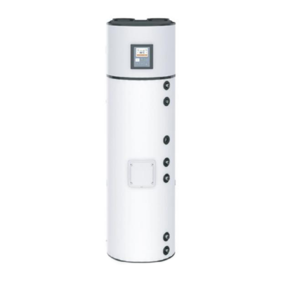
SPECIFICATION COMPONENTS AQUA HP Terminal dimensions Description of outlets 1970 G 1“ M C – Cold Water Inlet G 1“ M G 1“ M G 3/4 “ M R – Recirculation 1025 G 1 1/4 “ M Mg – Mg anode 1343 G 1/2 “... -
Page 8: Heat Pump Principle
A cooling system, at the top, responsible for transferring heat from ambient air to sanitary water. Air extraction duct Evaporator Compressor Expansion valve High pressure switch Solenoid valve Low pressure switch Filter Condensate drain Electrical box HEAT PUMP PRINCIPLE Ambient air inlet Expansion Evaporator Compresor... -
Page 9: Technické Parametry
1. The cooling fluid (R134a) is compressed in the high efficient compressor, raising its pressure and temperature. 2. In the condenser (not in direct contact with the water), the heat energy in the cooling fluid is transmitted to the water in the water storage heater. 3. -
Page 10: Transport
TRANSPORT The equipment must be carried in an upright position. The equipment must be raised and lowered with extreme care, to avoid impact that could damage the material. Make sure the belts and/or transportation straps do not damage the material. Always use suitable means to transport the material (pallet lift, forklift, etc.) WARNING Correct transport position... -
Page 11: Installation
INSTALLATION SAFETY AND CONTROL DEVICES 4.1.1 High/Low Pressure Switch In case of running outside the range of pressures recommended and defined by the supplier, the equipment will switch off and indicate error in the electronic panel. 4.1.2 Thermal fuse Thermal fuse is factory set by the manufacturer, and ensures that the water temperature in the hot water tank does not exceed the maximum value. -
Page 12: Pressure Reducing Valve
4.1.7 Pressure Reducing Valve * The pressure reducing valve must always be installed upstream from the safety device, and ready to activate in situations when the pressure in the circuit exceeds 3 bar (0.3MPa). This valve comes with a pressure gauge. * Parts that are not delivered by the manufacturer. -
Page 13: Air Inlet/Outlet Installation
Adjust the levelling legs of the appliance. Acceptable is the tilt angle 1° rearward. If equipment tilts other than back- wards, this will cause condensates to deposit in the tank. WARNING AIR INLET/OUTLET INSTALLATION As the AQUA HP absorbs heat during its operation, the air flow (inlet/out- let) must be directed to unheated areas. -
Page 14: Installation With Ducts
4.4.2 Installation with Ducts The Heat Pump is prepared to install ducts with diameter of 160 mm and 190 mm, in its air intake and extraction zones: Inner Ø 160 mm Outer Ø 190 mm Max Length Ducts Ø 160 Ø... - Page 15 Using Ambient Air The monobloc unit may also be placed in a heated room, but the air flow must be directed to an unheated room. Bear in mind that because of air flow, cooling the unheated room can affect the adjacent heated rooms.
- Page 16 Using Ambient and Outside Air A branched duct can be used to inflate air into the equipment. So, you can get hot air in the summer, from the outside, and hot air in the winter from an unheated room. HEATED OR UNHEATED AREA UNHEATED min 50 m...
-
Page 17: Plumbing Fixture
PLUMBING FIXTURE EXPLANATORY NOTES [1] Shutoff valve [7] Drain Valve [2] Pressure Reducing Valve (3 bar / 0,3 MPa) [8] Circulating pump [3] Return Valve [9] Thermostatic Mixing Valve [4] Safety valve (7 bar / 0,7 MPa) [A] Cold Water Inlet [5] Drainage Siphon [B] Hot Water Outlet [6] Expansion Vessel... -
Page 18: Condensate
The water you use may contain impurities and/or substances damaging to the system and even harmful to your health. Make sure you use water with quality fitting for home consumption. The following table indicates some parameters that, when exceeded, must be chemically treated. -
Page 19: Wiring Diagram
WIRING DIAGRAM EXPLANATORY NOTES RES – Electrical backup heater (2,2 kW) HP – High pressure switch S1 – Water temperature sensor LP – Low pressure switch S2 – Ambient temperature sensor COMP – Compressor S3 – Evaporator temperature sensor TB – Thermal fuse VENT –... -
Page 20: Control And Programming
CONTROL AND PROGRAMMING CONTROL PANEL The control panel of the Thermodynamic Solar system Eco is simple and intuitive. It enables the configuration of several operating parameters according to the operating mode selected by the user. It comprises six command keys (ON / OFF / CANCEL, MENU, COMP ▲, E-HEATER ▼, DISINFECT and OK / LOCK that enable checking the running of the equipment, consult and change parameters. -
Page 21: Display
DISPLAY 5.3.1 Display description 5.3.2 Symbols Symbol Description Appliance in ECO service mode Appliance in AUTO service mode Appliance in BOOST service mode Timer clock control Low Ambient Temperature protection Defrost Compressor Electrical heater Disinfect, Chrono function Vacation mode Recirculation pump function Solar function °C Water temperature... -
Page 22: Symbols In The Appliance's Operation
5.3.3 Symbols in the appliance's operation Symbol Description Compressor ACTIVATED Compressor RUNNING Electrical heater ACTIVATED Electrical heater RUNNING Electrical heater ACTIVATED when S1 < P08 and/or P07 ˃ Temperature S3 (Auto Mode) Electrical heater ACTIVATED when compressor continuous running time exceeds T05 (Auto mode) Electrical heater ACTIVATED manually Fan RUNNING... -
Page 23: Putting Into Operation
PUTTING INTO OPERATION Before starting, check whether the installation is set up according to the recommendations and that everything is in conformity, then you may plug your equipment to the power supply. After switching on your equipment, you should wait a few seconds until the controller begins to work. Then you may start your equipment following these instructions: System is shut OFF Press key COMP to start... -
Page 24: Eco Mode
5.5.1 mode In ECO operating mode, the equipment runs only as a Heat Pump to heat the water in the storage water heater. Thus, we could generate a greater efficiency, and savings for the user. Every time the user feels it necessary, may switch on the support electrical heater, using this mode, manually pressing the key (E-HEATER). -
Page 25: Tcc Mode
5.5.5 mode The TCC function provides the possibility of raising the water temperature when an alternative power source is available (solar photovoltaic, wind or other), increasing the efficiency of the heat pump and making the alternative power source profitable. To this end, it is sufficient to connect a cable from the inverter to the equipment's control board. The cable connection on the control board must be made at the voltage-controlled terminals. -
Page 26: Chrono Scheduling Of The Heat Pump
5.5.6 Chrono scheduling of the heat pump The heat pump has an internal clock that allows the user to set two periods of operation for the control of the equipment. These periods can be distinctly defined as weekly (Monday to Friday) or weekend (Saturday and Sunday). -
Page 27: Chrono Scheduling Of The Recirculation Pump
5.5.7 Chrono scheduling of the recirculation pump The heat pump has an internal clock that allows the user to set two periods of operation for the pump of recirculation. These periods can be distinctly defined as weekly (Monday to Friday) or weekend (Saturday and Sunday). - Page 28 Parameter P12 = 4: The heat pump controller assumes the control of a recirculation pump in parallel with the heat pump control. The pump of recirculation is driven by the hourly period set by the user and the temperature in the heat accumulator.
-
Page 29: Additional Functions
ADDITIONAL FUNCTIONS 5.6.1 Disinfection Mode The Monobloc electronic control features the Disinfect function, which consists of a water heating cycle up to 65 °C, for a period of time long enough to prevent the formation of germs inside the tank. The Disinfect function can be set automatically or manually. -
Page 30: Number Of Showers Available
NUMBER OF SHOWERS AVAILABLE The user can consult the number of showers available on the home page of the graphical interface (display) by using a volume of hot water at a temperature of 40 °C or more. On the initial page of the display, the parameter mentioned in this chapter will be displayed by resorting to the icon of a shower, with the number indicating the number of showers being positioned below. -
Page 31: Checking Good Running Condition
CHECKING GOOD RUNNING CONDITION To check that your equipment is working properly put it into operation and wait at least 20 to 30 minutes and then check the following conditions: • The air temperature at the outlet of the evaporator should be 3°C to 4°C lower than the temperature of the inlet air. - Page 32 Code Type Description Min Max Setting Units H02 TCC – Gradient de P02 TCC °C P03 – Setpoint start defrost cycle °C P04 – Temperature finish defrost cycle °C P05 – Safety temperature °C P06 – Setpoint disinfect °C P07 – Temp. min Evaporator to activate electrical °C heater (AUTO mode) P08 - Temp.
- Page 33 Temperature Probe 1 Temperature Probe 2 Temperature Probe 3 Temperature Probe 4 P01 Setpoint compressor H01 Gradient P01 P02 Setpoint Electrical heater H02 Gradient P02 P05 Water temperature alarm INFO P06 Setpoint anti-legionella P10 Setpoint to LAT Mode starts H10 Gradient P10 P12 Additional Functions T01 Delay compressor starts running T05 Maximum time compressor running...
-
Page 34: Errors
ERRORS The installation, assembly and repair of the equipment can only be carried out by qualified technicians. Symbol Description Problem / Checking Er01 – S1 Probe 1 OFF. • Lack of temperature probe. Check for probe. Er02 – S2 Probe 2 OFF. •... -
Page 35: Probe Chart
PROBE CHART The probes installed in the equipment (S1, S2, S3 e S4) are NTC 10kΩ@25°C. Dependence of sensor's resistance on temperature Temperature (°C) - 35 -... -
Page 36: Troubleshooting
TROUBLESHOOTING Problem Possible Causes How to Proceed Check the power supply Power supply failure Check the corresponding circuit breaker Failure in electronic board Check the integrity of the electronic board’s Cable damaged or disconnect- ed electric circuit Low temperature programmed as Adjust the temperature of the set-point. -
Page 37: System Maintenance
Problem Possible Causes How to Proceed The running of the equipment depends on Low external temperature weather conditions The running of the equipment depends on the Low water temperature inlet water temperature Too much usage of the Make sure the installation is supplied with the electric heater as a Low voltage installation indicated value for voltage... -
Page 38: General Inspection
Although the coolant in the cooling circuit is ecological, it must not be discharged freely into the environment. Ecological disposal must be ensured. 11.1 GENERAL INSPECTION The coolant in the device can be handled ONLY by a qualified refrigeration technician with valid authorization. -
Page 39: Filter Of Reduction Valve
The wear of the anode always depends on the characteristics of the water you use. Thus, checking the condition of the anode is very important, particularly in the first years of the installation. To check the condition of your anode, follow these steps: •... - Page 40 Warranty This warranty covers all defects to the confirmed materials, excluding the payment of any type of personal damage indemnity caused directly or indirectly by the materials. The periods indicated below start from the purchase date of the apparatus, 6 months at the latest from the leaving date from our storage warehouses.
Need help?
Do you have a question about the Drazice Aqua HP 250 and is the answer not in the manual?
Questions and answers