Table of Contents
Advertisement
Quick Links
Advertisement
Table of Contents

Related Manuals for IEI Technology KINO-DQM871-i1


Summary of Contents for IEI Technology KINO-DQM871-i1
- Page 1 KINO-DQM871-i1 Mini-ITX SBC MODEL: KINO-DQM871-i1 Mini-ITX SBC with 4th Generation 22nm Intel® Core™ CPU Up to 16.0 GB DDR3, HDMI, LVDS, DisplayPort, VGA Dual GbE, SATA 6Gb/s, USB 3.2 Gen 1, PCIe Mini, PCIe x16, Intel® AMT 9.0, IPMI 2.0, RoHS...
- Page 2 KINO-DQM871-i1 Mini-ITX SBC Revision Date Version Changes June 23, 2021 1.03 Deleted i7, i3E and CE SKUs Updated Section 2.3: Packing List Updated Chapter 6: Software Drivers Changed audio IC to ALC888S September 23, 2015 1.02 Modified the total number of the internal USB 2.0 ports July 16, 2015 1.01...
- Page 3 KINO-DQM871-i1 Mini-ITX SBC Copyright COPYRIGHT NOTICE The information in this document is subject to change without prior notice in order to improve reliability, design and function and does not represent a commitment on the part of the manufacturer. In no event will the manufacturer be liable for direct, indirect, special, incidental, or consequential damages arising out of the use or inability to use the product or documentation, even if advised of the possibility of such damages.
- Page 4 KINO-DQM871-i1 Mini-ITX SBC Manual Conventions WARNING Warnings appear where overlooked details may cause damage to the equipment or result in personal injury. Warnings should be taken seriously. CAUTION Cautionary messages should be heeded to help reduce the chance of losing data or damaging the product.
-
Page 5: Table Of Contents
KINO-DQM871-i1 Mini-ITX SBC Table of Contents 1 INTRODUCTION ......................1 1.1 I ......................2 NTRODUCTION 1.2 B ........................3 ENEFITS 1.3 F ........................3 EATURES 1.4 C ......................4 ONNECTORS 1.5 D ....................... 5 IMENSIONS 1.6 D ........................ 6 1.7 T .................. - Page 6 KINO-DQM871-i1 Mini-ITX SBC 3.2.11 IPMI Active LED Connector ................27 3.2.12 Keyboard/Mouse Connector ................28 3.2.13 LAN Active LED Connector ................29 3.2.14 LVDS Connector .................... 30 3.2.15 LVDS Backlight Connector ................32 3.2.16 PCIe Mini Card Slot ..................32 3.2.17 PCI Express x16 Slot ..................
- Page 7 KINO-DQM871-i1 Mini-ITX SBC RIS-1010 M ................64 ODULE NSTALLATION 4.6 PCI ................66 NSTALLATION 4.7 J ....................67 UMPER ETTINGS 4.7.1 AT/ATX Mode Selection ................... 68 4.7.2 Clear CMOS ..................... 69 4.7.3 LVDS Voltage Selection ..................70 4.7.4 LVDS Resolution Selection ................71 4.8 C...
- Page 8 KINO-DQM871-i1 Mini-ITX SBC 5.3.10.1 Serial Port n Configuration ..............95 5.3.11 Serial Port Console Redirection ..............100 5.3.12 iEi Feature ....................104 5.4 C ......................... 105 HIPSET 5.4.1 PCH-IO Configuration .................. 106 5.4.1.1 PCI Express Configuration ..............108 5.4.2 System Agent (SA) Configuration ..............109 5.4.2.1 Graphics Configuration ................
- Page 9 KINO-DQM871-i1 Mini-ITX SBC H.1 R HS II D (2015/863/EU) ..............145 IRECTIVE H.2 C HS ......................146 HINA Page ix...
- Page 10 List of Figures Figure 1-1: KINO-DQM871-i1 ......................2 Figure 1-2: Connectors ........................4 Figure 1-3: KINO-DQM871-i1 Dimensions (mm) ................5 Figure 1-4: Data Flow Diagram ...................... 6 Figure 3-1: Connector and Jumper Locations ................15 Figure 3-2: ATX Power Signal Connector Location ..............18 Figure 3-3: Battery Connector Location ..................
- Page 11 KINO-DQM871-i1 Mini-ITX SBC Figure 3-27: SO-DIMM Connector Locations ................45 Figure 3-28: SPI Flash Connector Location ................46 Figure 3-29: EC SPI Flash Connector Location ................. 47 Figure 3-30: TPM Connector Location ..................48 Figure 3-31: USB 2.0 Connector Locations ................49 Figure 3-32: USB 3.2 Gen 1 Connector Location ..............
- Page 12 KINO-DQM871-i1 Mini-ITX SBC List of Tables Table 1-1: Technical Specifications ....................9 Table 2-1: Packing List ......................... 12 Table 2-2: Optional Items ......................13 Table 3-1: Peripheral Interface Connectors ................17 Table 3-2: Rear Panel Connectors ....................17 Table 3-3: ATX Power Signal Connector Pinouts ..............18 Table 3-4: Battery Connector Pinouts ..................
- Page 13 KINO-DQM871-i1 Mini-ITX SBC Table 3-28: SATA 3Gb/s Drive Connector Pinouts ..............42 Table 3-29: SATA Power Connector Pinouts ................43 Table 3-30: SMBus Connector Pinouts ..................44 Table 3-31: SPI Flash Connector Pinouts .................. 46 Table 3-32: EC SPI Flash Connector Pinouts ................47 Table 3-33: TPM Connector Pinouts ...................
- Page 14 KINO-DQM871-i1 Mini-ITX SBC BIOS Menus BIOS Menu 1: Main ........................80 BIOS Menu 2: Advanced ......................82 BIOS Menu 3: ACPI Settings ....................... 82 BIOS Menu 4: RTC Wake Settings ....................83 BIOS Menu 5: Trusted Computing ....................85 BIOS Menu 6: CPU Configuration ....................86 BIOS Menu 7: SATA Configuration .....................
-
Page 15: Introduction
KINO-DQM871-i1 Mini-ITX SBC Chapter Introduction Page 1... -
Page 16: Introduction
The KINO-DQM871-i1 features Intelligent Platform Management Interface (IPMI) that helps lower the overall costs of server management by enabling users to maximize IT resource, save time and manage multiple systems. The KINO-DQM871-i1 supports IPMI 2.0 through the optional iRIS-1010 module. -
Page 17: Benefits
Low power consumption Wide range of I/O interfaces Triple independent display support 1.3 Features Some of the KINO-DQM871-i1 motherboard features are listed below: Mini-ITX form factor RoHS compliant 4th generation 22mm Intel® Core™ i5-4402E processor ... -
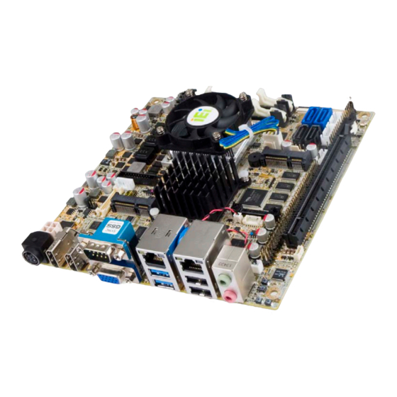
Page 18: Connectors
KINO-DQM871-i1 Mini-ITX SBC 1.4 Connectors The connectors on the KINO-DQM871-i1 are shown in the figure below. Figure 1-2: Connectors Page 4... -
Page 19: Dimensions
KINO-DQM871-i1 Mini-ITX SBC 1.5 Dimensions The main dimensions of the KINO-DQM871-i1 are shown in the diagram below. Figure 1-3: KINO-DQM871-i1 Dimensions (mm) Page 5... -
Page 20: Data Flow
KINO-DQM871-i1 Mini-ITX SBC 1.6 Data Flow Figure 1-4 shows the data flow between the system chipset, the CPU and other components installed on the motherboard. Figure 1-4: Data Flow Diagram Page 6... -
Page 21: Technical Specifications
KINO-DQM871-i1 Mini-ITX SBC 1.7 Technical Specifications KINO-DQM871-i1 technical specifications are listed in Table 1-1. Specification KINO-DQM871-i1 Form Factor Mini-ITX On-board Processor Intel® Core™ i5-4402E processor with Intel® AMT 9.0 support (1.6 GHz, dual-core, 3 MB cache, 25 W TDP) System Chipset Intel®... - Page 22 KINO-DQM871-i1 Mini-ITX SBC I/O Interface Connectors 1 x VGA (up to 1920 x 1200 @ 60 Hz) Display Output Ports (Triple Display 2 x HDMI (up to 2500 x 1600 @ 60 Hz) Supported) 1 x 18/24-bit dual-channel LVDS by CH7511B DP to LVDS converter (up...
-
Page 23: Table 1-1: Technical Specifications
KINO-DQM871-i1 Mini-ITX SBC Physical Specifications 170 mm x 170 mm Dimensions Weight GW/NW 900 g/450 g Table 1-1: Technical Specifications Page 9... -
Page 24: Packing List
KINO-DQM871-i1 Mini-ITX SBC Chapter Packing List Page 10... -
Page 25: Anti-Static Precautions
Only handle the edges of the PCB: Don't touch the surface of the motherboard. Hold the motherboard by the edges when handling. 2.2 Unpacking Precautions When the KINO-DQM871-i1 is unpacked, please do the following: Follow the antistatic guidelines above. -
Page 26: Packing List
If any of the components listed in the checklist below are missing, do not proceed with the installation. Contact the IEI reseller or vendor the KINO-DQM871-i1 was purchased from or contact an IEI sales representative directly by sending an email to sales@ieiworld.com... -
Page 27: Optional Items
KINO-DQM871-i1 Mini-ITX SBC 2.4 Optional Items These optional items are available. Item and Part Number Image IPMI 2.0 adapter card with AST1010 BMC chip (without KVM over IP function) for PCIe Mini socket interface (P/N: iRIS-1010-R10) RS-232 cable with Bracket... -
Page 28: Connector Pinouts
KINO-DQM871-i1 Mini-ITX SBC Chapter Connector Pinouts Page 14... -
Page 29: Peripheral Interface Connectors
KINO-DQM871-i1 Mini-ITX SBC 3.1 Peripheral Interface Connectors Section 3.1.1 shows peripheral interface connector locations. Section 3.1.2 lists all the peripheral interface connectors seen in Section 3.1.1. 3.1.1 Layout The figure below shows the on-board peripheral connectors, rear panel peripheral connectors and on-board jumpers. -
Page 30: Peripheral Interface Connectors
KINO-DQM871-i1 Mini-ITX SBC 3.1.2 Peripheral Interface Connectors The table below shows a list of the peripheral interface connectors on the KINO-DQM871-i1. Detailed descriptions of these connectors can be found below. Connector Type Label ATX power signal connector 3-pin header PS_ON1... -
Page 31: External Interface Panel Connectors
USB 3.2 Gen 1 connector 20-pin box header Table 3-1: Peripheral Interface Connectors 3.1.3 External Interface Panel Connectors The table below lists the rear panel connectors on the KINO-DQM871-i1. Detailed descriptions of these connectors can be found in a later section. Connector Type... -
Page 32: Internal Peripheral Connectors
Internal peripheral connectors are found on the motherboard and are only accessible when the motherboard is outside of the chassis. This section has complete descriptions of all the internal, peripheral connectors on the KINO-DQM871-i1. 3.2.1 ATX Power Signal Connector CN Label:... -
Page 33: Battery Connector
This is connected to the system battery. The battery provides power to the system clock to retain the time when power is turned off. NOTE: It is recommended to attach the RTC battery onto the system chassis in which the KINO-DQM871-i1 is installed. Figure 3-3: Battery Connector Location... -
Page 34: Chassis Intrusion Connector
KINO-DQM871-i1 Mini-ITX SBC Description Battery+ Ground Table 3-4: Battery Connector Pinouts 3.2.3 Chassis Intrusion Connector CN Label: CHASSIS1 CN Type: 2-pin header CN Location: See Figure 3-4 CN Pinouts: See Table 3-5 The chassis intrusion connector is for a chassis intrusion detection sensor or switch that detects if a chassis component is removed or replaced. -
Page 35: Digital I/O Connector
KINO-DQM871-i1 Mini-ITX SBC 3.2.4 Digital I/O Connector CN Label: DIO1 10-pin header CN Type: CN Location: See Figure 3-5 CN Pinouts: See Table 3-6 The digital I/O connector provides programmable input and output for external devices. The digital I/O provides 4-bit output and 4-bit input. -
Page 36: Figure 3-6: Displayport Connector Location
KINO-DQM871-i1 Mini-ITX SBC CN Pinouts: See Table 3-7 The internal DisplayPort connector supports HDMI, LVDS, VGA, DVI and DisplayPort connection with up to 3840 x 2160 resolutions. Figure 3-6: DisplayPort Connector Location Description Description TMDS_B_HPD# AUX_P2 AUX_N2 DP2_CFG1 DPB_OB_LANE2_P DPB_OB_LANE3_P... -
Page 37: Ec Debug Connector
KINO-DQM871-i1 Mini-ITX SBC 3.2.6 EC Debug Connector CN Label: LPT_DB1 20-pin FPC CN Type: CN Location: See Figure 3-7 CN Pinouts: See Table 3-8 The connector is for EC debug only. Figure 3-7: BIOS Debug Port Location Description Description KSI0... -
Page 38: Fan Connector (Cpu)
KINO-DQM871-i1 Mini-ITX SBC 3.2.7 Fan Connector (CPU) CN Label: CPU_FAN1 4-pin wafer CN Type: CN Location: See Figure 3-8 CN Pinouts: See Table 3-9 The fan connector attaches to a CPU cooling fan. Figure 3-8: CPU Fan Connector Location Description... -
Page 39: Front Panel Connector
KINO-DQM871-i1 Mini-ITX SBC CN Location: See Figure 3-9 CN Pinouts: See Table 3-10 The fan connector attaches to a system cooling fan. Figure 3-9: System Fan Connector Location Description +V12S Rotation Signal PWM Control Signal Table 3-10: System Fan Connector Pinouts 3.2.9 Front Panel Connector... -
Page 40: Iris Module Slot
KINO-DQM871-i1 Mini-ITX SBC The front panel connector connects to the indicator LEDs and buttons on the computer's front panel. Figure 3-10: Front Panel Connector Location Description Description Power PWR_LED+ Buzzer SPKR+ PWR_LED- PWR_BTN+ SPKR- Power Button PWR_BTN- HDD_LED+ Reset Reset+... -
Page 41: Ipmi Active Led Connector
The iRIS module slot is designed to install the IEI iRIS-1010 IPMI 2.0 module only. DO NOT install other modules into the iRIS module slot. Doing so may cause damage to the KINO-DQM871-i1. Figure 3-11: iRIS Module Slot Location 3.2.11 IPMI Active LED Connector... -
Page 42: Keyboard/Mouse Connector
KINO-DQM871-i1 Mini-ITX SBC Figure 3-12: IPMI Active LED Connector Description IPMI_LED+ IPMI_LED- Table 3-12: IPMI Active LED Connector Pinouts 3.2.12 Keyboard/Mouse Connector CN Label: KB_MS1 6-pin wafer CN Type: CN Location: See Figure 3-13 CN Pinouts: See Table 3-13 The keyboard/mouse connector connects to a PS/2 Y-cable that can be connected to a PS/2 keyboard and mouse. -
Page 43: Lan Active Led Connector
KINO-DQM871-i1 Mini-ITX SBC Figure 3-13: Keyboard/Mouse Connector Location Description VCC5_KBMS Mouse Data Mouse Clock Keyboard Data Keyboard Clock Table 3-13: Keyboard/Mouse Connector Pinouts 3.2.13 LAN Active LED Connector CN Label: LAN_ACT_LED1 4-pin header CN Type: CN Location: See Figure 3-14... -
Page 44: Lvds Connector
KINO-DQM871-i1 Mini-ITX SBC Figure 3-14: LAN Active LED Connector Location Description Description LAN1_LINK_ACT- V_3P3_LAN LAN2_LINK_ACT- +3.3A Table 3-14: LAN Active LED Connector Pinouts 3.2.14 LVDS Connector CN Label: LVDS1 30-pin crimp CN Type: CN Location: See Figure 3-15 CN Pinouts: See Table 3-15 The LVDS connector is for an LCD panel connected to the board. -
Page 45: Figure 3-15: Lvds Connector Location
KINO-DQM871-i1 Mini-ITX SBC Figure 3-15: LVDS Connector Location Description Description LVDS_A_TX0-P LVDS_A _TX0-N LVDS_A_TX1-P LVDS_A _TX1-N LVDS_A_TX2-P LVDS_A _TX2-N LVDS_A_TXCLK-P LVDS_A _TXCLK-N LVDS_A_TX3-P LVDS_A _TX3-N LVDS_B _TX0-P LVDS_B _TX0-N LVDS_B _TX1-P LVDS_B _TX1-N LVDS_B _TX2-P LVDS_B _TX2-N LVDS_B _TXCLK-P LVDS_B _TXCLK-N... -
Page 46: Lvds Backlight Connector
KINO-DQM871-i1 Mini-ITX SBC 3.2.15 LVDS Backlight Connector CN Label: INV1 5-pin wafer CN Type: CN Location: See Figure 3-16 CN Pinouts: See Table 3-16 The backlight inverter connectors provide power to LCD panels. Figure 3-16: LVDS Backlight Inverter Connector Description... -
Page 47: Figure 3-17: Pcie Mini Card Slot Location
KINO-DQM871-i1 Mini-ITX SBC CN Pinouts: See Table 3-17 The PCIe Mini card slot enables a PCIe Mini card expansion module to be connected to the board. Cards supported include among others PCIe Mini cards and mSATA cards. Figure 3-17: PCIe Mini Card Slot Location... -
Page 48: Pci Express X16 Slot
KINO-DQM871-i1 Mini-ITX SBC Description Description USBD+ VCC3 VCC3 SATA_DET4_R_N CL_CK CL_DATA +1.5V CL_RST_N MSATA_SEL# VCC3 Table 3-17: PCIe Mini Card Slot Pinouts 3.2.17 PCI Express x16 Slot CN Label: PCIEX16_1 CN Type: PCIe x16 slot CN Location: See Figure 3-18... -
Page 49: Table 3-18: Pcie X16 Side A Pinouts
KINO-DQM871-i1 Mini-ITX SBC Description Description Description Description Name HSIn(1) HSIp(6) HSIp(11) PRSNT#1 HSIn(6) HSIn(11) +12v +12v HSIp(2) HSIn(2) HSIp(7) HSIp(12) JTAG2 HSIn(7) HSIn(12) JTAG3 JTAG4 HSIp(3) RSVD JTAG5 HSIn(3) HSIp(13) +3.3v HSIp(8) HSIn(13) +3.3v RSVD HSIn(8) PWRGD RSVD HSIp(14) REFCLK+... -
Page 50: Power Button (On-Board)
Table 3-19: PCIe x16 Side B Pinouts 3.2.18 Power Button (On-board) CN Label: PWR_SW1 Push button CN Type: CN Location: See Figure 3-19 Push the on-board power button to power on the KINO-DQM871-i1. Figure 3-19: On-board Power Button Location Page 36... -
Page 51: Power Connector (12V)
KINO-DQM871-i1 Mini-ITX SBC 3.2.19 Power Connector (12V) CN Label: PWR2 4-pin connector CN Type: CN Location: See Figure 3-20 CN Pinouts: See Table 3-20 The power connector is connected to an external power supply and supports 12V power input. Power is provided to the system, from the power supply through this connector. -
Page 52: Figure 3-21: Rs-232 Serial Port Connector Location
KINO-DQM871-i1 Mini-ITX SBC Figure 3-21: RS-232 Serial Port Connector Location Description Description -NDCD2 -NDSR2 NSIN2 -NRTS2 NSOUT2 -NCTS2 -NDTR2 -XRI2 Table 3-21: COM2 Pinouts Description Description -NDCD3 -NDSR3 NSIN3 -NRTS3 NSOUT3 -NCTS3 -NDTR3 -XRI3 Table 3-22: COM3 Pinouts Page 38... -
Page 53: Rs-422/485 Serial Port Connector (Com6)
KINO-DQM871-i1 Mini-ITX SBC Description Description -NDCD4 -NDSR4 NSIN4 -NRTS4 NSOUT4 -NCTS4 -NDTR4 -XRI4 Table 3-23: COM4 Pinouts Description Description -NDCD5 -NDSR5 NSIN5 -NRTS5 NSOUT5 -NCTS5 -NDTR5 -XRI5 Table 3-24: COM5 Pinouts 3.2.21 RS-422/485 Serial Port Connector (COM6) CN Label: COM6... -
Page 54: Sata 6Gb/S Drive Connectors
KINO-DQM871-i1 Mini-ITX SBC Figure 3-22: RS-422/485 Serial Port Connector Location Description RXD422- RXD422+ TXD422+/TXD485+ TXD422-/TXD485- Table 3-25: RS-422/485 Serial Port Connector Pinouts Use the optional RS-422/485 cable to connect to a serial device. The pinouts of the D-sub 9 connector are listed below. -
Page 55: Sata 3Gb/S Drive Connectors
KINO-DQM871-i1 Mini-ITX SBC CN Location: See Figure 3-23 CN Pinouts: See Table 3-27 The SATA connectors connect to SATA hard drives or optical drives with data transfer speeds as high as 6Gb/s. Figure 3-23: SATA 6Gb/s Drive Connector Locations Description Table 3-27: SATA 6Gb/s Drive Connector Pinouts 3.2.23 SATA 3Gb/s Drive Connectors... -
Page 56: Sata Power Connectors
KINO-DQM871-i1 Mini-ITX SBC CN Pinouts: See Table 3-28 The SATA connectors connect to SATA hard drives or optical drives with data transfer speeds as high as 3Gb/s. Figure 3-24: SATA 3Gb/s Drive Connector Locations Description Table 3-28: SATA 3Gb/s Drive Connector Pinouts 3.2.24 SATA Power Connectors... -
Page 57: Smbus Connector
KINO-DQM871-i1 Mini-ITX SBC Use the SATA Power Connector to connect to SATA device power connections. Figure 3-25: SATA Power Connector Locations Description +V12S +V5S Table 3-29: SATA Power Connector Pinouts 3.2.25 SMBus Connector CN Label: SMB1 4-pin wafer CN Type:... -
Page 58: So-Dimm Connectors
KINO-DQM871-i1 Mini-ITX SBC Figure 3-26: SMBus Connector Location Description SMB_DATA SMB_CLK +V5S Table 3-30: SMBus Connector Pinouts 3.2.26 SO-DIMM Connectors CN Label: DIMM1, DIMM2 CN Type: 204-pin DDR3 SO-DIMM connector CN Location: See Figure 3-27 The SO-DIMM connector is for installing memory on the system. -
Page 59: Spi Flash Connector
KINO-DQM871-i1 Mini-ITX SBC Figure 3-27: SO-DIMM Connector Locations 3.2.27 SPI Flash Connector CN Label: SPI1 CN Type: 6-pin wafer CN Location: See Figure 3-28 CN Pinouts: See Table 3-31 The 6-pin SPI Flash connector is used to flash the BIOS. -
Page 60: Spi Flash Connector (Ec)
KINO-DQM871-i1 Mini-ITX SBC Figure 3-28: SPI Flash Connector Location Description +V3.3M_SPI_CON SPI_CS0_N SPI_SO SPI_CLK SPI_SI Table 3-31: SPI Flash Connector Pinouts 3.2.28 SPI Flash Connector (EC) CN Label: CN Type: 2-pin header CN Location: See Figure 3-29 CN Pinouts: See Table 3-32 The 2-pin EC SPI Flash connector is used to flash the embedded controller (EC). -
Page 61: Tpm Connector
KINO-DQM871-i1 Mini-ITX SBC Figure 3-29: EC SPI Flash Connector Location Description SMCLK1_EC SMDAT1_EC Table 3-32: EC SPI Flash Connector Pinouts 3.2.29 TPM Connector CN Label: TPM1 CN Type: 20-pin header CN Location: See Figure 3-30 CN Pinouts: See Table 3-33 The Trusted Platform Module (TPM) connector secures the system on bootup. -
Page 62: Usb 2.0 Connectors
KINO-DQM871-i1 Mini-ITX SBC Figure 3-30: TPM Connector Location Description Description CLK_PCI_TPM LPC_FRAME# BUF_PLT_RST# LPC_AD3 LPC_AD2 +3.3V LPC_AD1 LPC_AD0 SMB_CLK SMB_DATA SB3V INT_SERIRQ PM_CLKRUN# SB3V TPM_DRQ#0 Table 3-33: TPM Connector Pinouts 3.2.30 USB 2.0 Connectors CN Label: USB1, USB2, USB3 CN Type:... -
Page 63: Figure 3-31: Usb 2.0 Connector Locations
KINO-DQM871-i1 Mini-ITX SBC Each USB header can connect to two USB devices. Figure 3-31: USB 2.0 Connector Locations Description Description DATA4- DATA5+ DATA4+ DATA5- Table 3-34: USB1 Pinouts Description Description DATA6- DATA7+ DATA6+ DATA7- Table 3-35: USB2 Pinouts Description Description... -
Page 64: Usb 3.2 Gen 1 Connector
KINO-DQM871-i1 Mini-ITX SBC Description Description DATA8+ DATA9- Table 3-36: USB3 Pinouts 3.2.31 USB 3.2 Gen 1 Connector CN Label: CN Type: 20-pin box header CN Location: See Figure 3-32 See Table 3-37 CN Pinouts: The connector supports two USB 3.2 Gen 1 (5Gb/s) connections. -
Page 65: External Interface Connectors
USB2_DP3 Table 3-37: USB 3.2 Gen 1 Connector Pinouts 3.3 External Interface Connectors Figure 3-33 shows the KINO-DQM871-i1 motherboard external interface connectors. The KINO-DQM871-i1 on-board external interface connectors are shown in Figure 3-33. Figure 3-33: External Interface Connectors 3.3.1 Audio Connector... -
Page 66: Ethernet And Usb 2.0 Connectors
KINO-DQM871-i1 Mini-ITX SBC Figure 3-34: Audio Jacks 3.3.2 Ethernet and USB 2.0 Connectors CN Label: LAN2_USB2 CN Type: RJ-45 and USB Type-A combo connector CN Location: See Figure 3-33 See Table 3-38 and Table 3-40 CN Pinouts: The LAN connector connects to a local network. The LAN2 connector supports IPMI 2.0. -
Page 67: Ethernet And Usb 3.2 Gen 1 Connectors
KINO-DQM871-i1 Mini-ITX SBC Description Description on: linked off: 10 Mb/s blinking: data is being sent/received green: 100 Mb/s orange: 1000 Mb/s Table 3-39: Connector LEDs Each USB 2.0 connector can be connected to a USB device. Description VBUS Table 3-40: External USB 2.0 Port Pinouts 3.3.3 Ethernet and USB 3.2 Gen 1 Connectors... -
Page 68: Hdmi Connectors
KINO-DQM871-i1 Mini-ITX SBC Figure 3-36: Ethernet Connector Description Description on: linked off: 10 Mb/s blinking: data is being sent/received green: 100 Mb/s orange: 1000 Mb/s Table 3-42: Connector LEDs Each USB 3.2 Gen 1 (5Gb/s) connector can be connected to a USB device. -
Page 69: Power Connector (12 V, Power Adapter)
KINO-DQM871-i1 Mini-ITX SBC CN Pinouts: See Table 3-44 and Figure 3-37 The HDMI connector connects to a display device with HDMI interface. Description Description HDMI_DATA2 HDMI_CLK# HDMI_DATA2# HDMI_DATA1 HDMI_SCL HDMI_DATA1# HDMI_SDA HDMI_DATA0 HDMI_DATA0# HDMI_HPD HDMI_CLK+ Table 3-44: HDMI Connector Pinouts Figure 3-37: HDMI Connector 3.3.5 Power Connector (12 V, Power Adapter) -
Page 70: Serial Port Connector (Com1)
KINO-DQM871-i1 Mini-ITX SBC Figure 3-38: 4-pin Power Mini-DIN Connection 3.3.6 Serial Port Connector (COM1) CN Label: COM1 CN Type: D-sub 9 See Figure 3-33 CN Location: CN Pinouts: See Table 3-45 The serial port connects to a RS-232 serial communications device. -
Page 71: Vga Connector
KINO-DQM871-i1 Mini-ITX SBC 3.3.7 VGA Connector CN Label: VGA1 15-pin Female CN Type: CN Location: See Figure 3-33 CN Pinouts: See Figure 3-40 and Table 3-46 Use the VGA connector to connect to a monitor that accepts a standard VGA input. -
Page 72: Installation
KINO-DQM871-i1 Mini-ITX SBC Chapter Installation Page 58... -
Page 73: Anti-Static Precautions
Electrostatic discharge (ESD) can cause serious damage to electronic components, including the KINO-DQM871-i1. Dry climates are especially susceptible to ESD. It is therefore critical to strictly adhere to the following anti-static precautions whenever the KINO-DQM871-i1, or any other electrical component, is handled. - Page 74 KINO-DQM871-i1 Mini-ITX SBC WARNING: The installation instructions described in this manual should be carefully followed in order to prevent damage to the KINO-DQM871-i1, KINO-DQM871-i1 components and injury to the user. Before and during the installation please DO the following: ...
-
Page 75: Cooling Kit Installation
KINO-DQM871-i1 Mini-ITX SBC 4.3 Cooling Kit Installation An IEI CPU cooling kit can be purchased separately (See Chapter 2). The cooling kit is comprised of a CPU heat sink and a cooling fan. WARNING: Do not wipe off (accidentally or otherwise) the pre-sprayed layer of thermal paste on the bottom of the heat sink. -
Page 76: Figure 4-2: Align The Cooling Kit
KINO-DQM871-i1 Mini-ITX SBC Step 2: Properly orient the cooling kit. The CPU fan cable must not interfere with the fan or other moving parts. Make sure the cable can be routed away from the moving parts. Step 3: Properly align the cooling kit. Line up the four screws with the screw holes on the support bracket below the board (Figure 4-2). -
Page 77: So-Dimm Installation
KINO-DQM871-i1 Mini-ITX SBC Figure 4-3: Secure the Cooling Kit 4.4 SO-DIMM Installation To install a SO-DIMM, please follow the steps below and refer to Figure 4-4. CAUTION: For dual channel configuration, always install two identical memory modules that feature the same capacity, timings, voltage, number of ranks and the same brand. -
Page 78: Iris-1010 Module Installation
The iRIS module slot is designed to install the IEI iRIS-1010 IPMI 2.0 module only. DO NOT install other modules into the iRIS module slot. Doing so may cause damage to the KINO-DQM871-i1. To install the iRIS-1010 module, please follow the steps below and refer to Figure 4-6. -
Page 79: Figure 4-5: Iris-1010 Module Installation
KINO-DQM871-i1 Mini-ITX SBC Step 1: Locate the iRIS module slot on the KINO-DQM871-i1. See Figure 3-11. Step 2: Remove the preinstalled retention screw on the screw pillar of the iRIS module slot as shown in Figure 4-5. Figure 4-5: iRIS-1010 Module Installation Step 3: Insert into the socket at an angle. -
Page 80: Pcie Mini Card Installation
Please refer to Section 4.10 for IPMI setup procedures. 4.6 PCIe Mini Card Installation Two PCIe Mini card slots are located on the KINO-DQM871-i1. To install the PCIe Mini card, please refer to the diagram and instructions below. Page 66... -
Page 81: Jumper Settings
KINO-DQM871-i1 Mini-ITX SBC Figure 4-7: PCIe Mini Card Installation Step 1: Insert into the socket at an angle. Line up the notch on the card with the notch on the connector. Slide the PCIe Mini card into the socket at an angle of about 20º. -
Page 82: At/Atx Mode Selection
Jumper Location: See Figure 4-8 Set the switch to select AT or ATX power mode for the KINO-DQM871-i1. AT power mode limits the system to on/off. ATX allows the system to use various power saving states and enter a standby state, so the system can be turned on remotely over a network. To configure, see the diagram below. -
Page 83: Clear Cmos
Jumper Location: See Figure 4-9 If the KINO-DQM871-i1 fails to boot due to improper BIOS settings, the clear CMOS jumper clears the CMOS data and resets the system BIOS information. To do this, push the clear CMOS button for three seconds, then restart the system. -
Page 84: Lvds Voltage Selection
KINO-DQM871-i1 Mini-ITX SBC Figure 4-9: Clear CMOS Jumper Location 4.7.3 LVDS Voltage Selection Jumper Label: JLCD_PWR1 6-pin header Jumper Type: Jumper Settings: See Table 4-2 Jumper Location: See Figure 4-10 This jumper selects the voltage of the LVDS connector. Description Short 1-2 +3.3 V (Default) -
Page 85: Lvds Resolution Selection
KINO-DQM871-i1 Mini-ITX SBC Figure 4-10: LVDS Voltage Selection Jumper Location 4.7.4 LVDS Resolution Selection Jumper Label: Jumper Type: DIP switch Jumper Settings: See Table 4-3 Jumper Location: See Figure 4-11 This jumper selects the resolution of the LCD panel connected to the LVDS connector. -
Page 86: Chassis Installation
The chassis should have fans and vents as necessary to keep things cool. The KINO-DQM871-i1 must be installed in a chassis with ventilation holes on the sides allowing airflow to travel through the heat sink surface. In a system with an individual... -
Page 87: Motherboard Installation
This section outlines the installation of peripheral devices to the onboard connectors. 4.9.1 SATA Drive Connection The KINO-DQM871-i1 is shipped with two SATA drive cable. To connect the SATA drive to the connector, please follow the steps below. Step 1: Locate the SATA connector and the SATA power connector. -
Page 88: Ipmi Setup Procedure
Install an iRIS-1010 module to the IPMI module socket (refer to Section 4.5). Step 2: Make sure at least one DDR3 SO-DIMM is installed on the KINO-DQM871-i1. Step 3: Connect an Ethernet cable to the RJ-45 connector labeled LAN2 (Figure 3-33). - Page 89 KINO-DQM871-i1 Mini-ITX SBC process. Enter the Intel® current ME password as it requires (the Intel® default password is admin). NOTE: To change the password, enter a new password following the strong password rule (containing at least one upper case letter, one lower case letter, one digit and one special character, and be at least eight characters).
-
Page 90: Bios
KINO-DQM871-i1 Mini-ITX SBC Chapter BIOS Page 76... -
Page 91: Introduction
KINO-DQM871-i1 Mini-ITX SBC 5.1 Introduction The BIOS is programmed onto the BIOS chip. The BIOS setup program allows changes to certain system settings. This chapter outlines the options that can be changed. NOTE: Some of the BIOS options may vary throughout the life cycle of the product and are subject to change without prior notice. -
Page 92: Getting Help
KINO-DQM871-i1 Mini-ITX SBC Function Left arrow Move to the item on the left hand side Right arrow Move to the item on the right hand side Increase the numeric value or make changes Decrease the numeric value or make changes... -
Page 93: Bios Menu Bar
KINO-DQM871-i1 Mini-ITX SBC 5.1.5 BIOS Menu Bar The menu bar on top of the BIOS screen has the following main items: Main – Changes the basic system configuration. Advanced – Changes the advanced system settings. Chipset – Changes the chipset settings. -
Page 94: Main
KINO-DQM871-i1 Mini-ITX SBC 5.2 Main The Main BIOS menu (BIOS Menu 1) appears when the BIOS Setup program is entered. The Main menu gives an overview of the basic system information. Aptio Setup Utility – Copyright (C) 2012 American Megatrends, Inc. -
Page 95: Advanced
KINO-DQM871-i1 Mini-ITX SBC System Overview The BIOS Information lists a brief summary of the BIOS. The fields in BIOS Information cannot be changed. The items shown in the system overview include: BIOS Information Processor Information Memory Information ... -
Page 96: Acpi Settings
KINO-DQM871-i1 Mini-ITX SBC Aptio Setup Utility – Copyright (C) 2012 American Megatrends, Inc. Main Advanced Chipset Boot Security Save & Exit > ACPI Settings System ACPI Parameters > RTC Wake Settings > Trusted Computing > CPU Configuration ---------------------- > SATA Configuration : Select Screen... -
Page 97: Rtc Wake Settings
KINO-DQM871-i1 Mini-ITX SBC ACPI Sleep State [S1 only (CPU Stop Clock)] Use the ACPI Sleep State option to specify the sleep state the system enters when it is not being used. S1 only (CPU Stop The system enters S1 (POS) sleep state. The... -
Page 98: Trusted Computing
KINO-DQM871-i1 Mini-ITX SBC Wake system with Fixed Time [Disabled] Use the Wake system with Fixed Time option to enable or disable the system wake on alarm event. Disabled The real time clock (RTC) cannot generate a wake EFAULT event ... -
Page 99: Bios Menu 5: Trusted Computing
KINO-DQM871-i1 Mini-ITX SBC Aptio Setup Utility – Copyright (C) 2012 American Megatrends, Inc. Advanced Configuration Enables or Disables BIOS Security Device Support [Disable] support for security device. O.S. will not Current Status Information show Security Device. NO Security Device Found... -
Page 100: Cpu Configuration
KINO-DQM871-i1 Mini-ITX SBC 5.3.4 CPU Configuration Use the CPU Configuration menu (BIOS Menu 6) to view detailed CPU specifications and configure the CPU. Aptio Setup Utility – Copyright (C) 2012 American Megatrends, Inc. Advanced CPU Configuration Enabled for Windows XP and Linux (OS optimized Intel(R) Core(TM) i3-4100E CPU @ 2.40GHz... - Page 101 KINO-DQM871-i1 Mini-ITX SBC Intel VT-x Technology: Indicates if Intel VT-x Technology is supported by the CPU. Intel SMX Technology: Indicates if Intel SMX Technology is supported by the CPU. EIST Technology: Indicates if the Enhanced Intel SpeedStep® Technology (EIST) is supported by the CPU.
-
Page 102: Sata Configuration
KINO-DQM871-i1 Mini-ITX SBC EIST [Enabled] Use the EIST BIOS option to enable or disable the Intel SpeedStep® Technology. Disables the Intel SpeedStep® Technology. Disabled Enables the Intel SpeedStep® Technology. Enabled EFAULT 5.3.5 SATA Configuration Use the SATA Configuration menu (BIOS Menu 7) to change and/or set the configuration of the SATA devices installed in the system. -
Page 103: Intel(R) Rapid Start Technology
KINO-DQM871-i1 Mini-ITX SBC Configures SATA devices as normal IDE device. EFAULT Configures SATA devices as AHCI device. AHCI RAID Configures SATA devices as RAID device. NOTE: Before accessing the RAID configuration utility, ensure to set the Option ROM Messages BIOS option in the Boot menu to Force BIOS. -
Page 104: Amt Configuration
KINO-DQM871-i1 Mini-ITX SBC Intel(R) Rapid Start Technology [Disabled] Use Intel(R) Rapid Start Technology option to enable or disable the Intel® Rapid Start Technology function. Disabled Intel® Rapid Start Technology is disabled EFAULT Intel® Rapid Start Technology is enabled Enabled 5.3.7 AMT Configuration... -
Page 105: Usb Configuration
KINO-DQM871-i1 Mini-ITX SBC Enabled Intel® AMT is enabled EFAULT Un-Configure ME [Disabled] Use the Un-Configure ME option to perform ME unconfigure without password operation. Not perform ME unconfigure Disabled EFAULT Enabled To perform ME unconfigure 5.3.8 USB Configuration Use the USB Configuration menu (BIOS Menu 10) to read USB configuration information and configure the USB settings. -
Page 106: Iwdd H/W Monitor
KINO-DQM871-i1 Mini-ITX SBC Legacy USB Support [Enabled] Use the Legacy USB Support BIOS option to enable USB mouse and USB keyboard support. Normally if this option is not enabled, any attached USB mouse or USB keyboard does not become available until a USB compatible operating system is fully booted with all USB drivers loaded. -
Page 107: Smart Fan Mode Configuration
KINO-DQM871-i1 Mini-ITX SBC PC Health Status The following system parameters and values are shown. The system parameters that are monitored are: CPU Temperature CPU_FAN1 Speed SYS_FAN1 Speed 5.3.9.1 Smart Fan Mode Configuration Use the Smart Fan Mode Configuration submenu (BIOS Menu 12) to configure the smart fan temperature and speed settings. -
Page 108: F81866 Super Io Configuration
KINO-DQM871-i1 Mini-ITX SBC Auto mode fan start/off temperature Use the + or – key to change the Auto mode fan start/off temperature value. Enter a decimal number between 1 and 100. Auto mode fan start PWM Use the + or – key to change the Auto mode fan start PWM value. Enter a decimal number between 1 and 100. -
Page 109: Serial Port N Configuration
KINO-DQM871-i1 Mini-ITX SBC 5.3.10.1 Serial Port n Configuration Use the Serial Port n Configuration menu (BIOS Menu 14) to configure the serial port n. Aptio Setup Utility – Copyright (C) 2012 American Megatrends, Inc. Advanced Serial Port n Configuration Enable or Disable Serial... - Page 110 KINO-DQM871-i1 Mini-ITX SBC IO=3F8h; Serial Port I/O port address is 3F8h and the interrupt IRQ=3, 4 address is IRQ3, 4 Serial Port I/O port address is 2F8h and the interrupt IO=2F8h; address is IRQ3, 4 IRQ=3, 4 ...
- Page 111 KINO-DQM871-i1 Mini-ITX SBC IO=2C8h; Serial Port I/O port address is 2C8h and the interrupt IRQ=3, 4 address is IRQ3, 4 5.3.10.1.3 Serial Port 3 Configuration Serial Port [Enabled] Use the Serial Port option to enable or disable the serial port.
- Page 112 KINO-DQM871-i1 Mini-ITX SBC 5.3.10.1.4 Serial Port 4 Configuration Serial Port [Enabled] Use the Serial Port option to enable or disable the serial port. Disabled Disable the serial port Enable the serial port Enabled EFAULT Change Settings [Auto] Use the Change Settings option to change the serial port IO port address and interrupt address.
- Page 113 KINO-DQM871-i1 Mini-ITX SBC Enabled Enable the serial port EFAULT Change Settings [Auto] Use the Change Settings option to change the serial port IO port address and interrupt address. The serial port IO port address and interrupt address...
-
Page 114: Serial Port Console Redirection
KINO-DQM871-i1 Mini-ITX SBC Change Settings [Auto] Use the Change Settings option to change the serial port IO port address and interrupt address. Auto The serial port IO port address and interrupt address EFAULT are automatically detected. Serial Port I/O port address is 2D8h and the interrupt IO=2D8h;... -
Page 115: Bios Menu 15: Serial Port Console Redirection
KINO-DQM871-i1 Mini-ITX SBC Aptio Setup Utility – Copyright (C) 2012 American Megatrends, Inc. Advanced COM1 Console Redirection Console Redirection [Disabled] Enable or Disable > Console Redirection Settings COM2 Console Redirection [Disabled] > Console Redirection Settings COM3 Console Redirection [Disabled] > Console Redirection Settings... - Page 116 KINO-DQM871-i1 Mini-ITX SBC NOTE: The following five options appear when the Console Redirection option is enabled. Terminal Type [ANSI] Use the Terminal Type option to specify the remote terminal type. VT100 The target terminal type is VT100 ...
- Page 117 KINO-DQM871-i1 Mini-ITX SBC Parity [None] Use the Parity option to specify the parity bit that can be sent with the data bits for detecting the transmission errors. None No parity bit is sent with the data bits. EFAULT ...
-
Page 118: Iei Feature
KINO-DQM871-i1 Mini-ITX SBC 5.3.12 iEi Feature Use the iEi Feature menu (BIOS Menu 16) to configure One Key Recovery function. Aptio Setup Utility – Copyright (C) 2012 American Megatrends, Inc. Advanced iEi Feature Auto Recovery Function Reboot and recover Auto Recovery Function... -
Page 119: Chipset
KINO-DQM871-i1 Mini-ITX SBC 5.4 Chipset Use the Chipset menu (BIOS Menu 17) to access the PCH IO and System Agent (SA) configuration menus. WARNING! Setting the wrong values for the Chipset BIOS selections in the Chipset BIOS menu may cause the system to malfunction. -
Page 120: Pch-Io Configuration
KINO-DQM871-i1 Mini-ITX SBC 5.4.1 PCH-IO Configuration Use the PCH-IO Configuration menu (BIOS Menu 18) to configure the PCH parameters. Aptio Setup Utility – Copyright (C) 2012 American Megatrends, Inc. Chipset Auto Power Button Status [Disable (ATX)] Select AC power state... - Page 121 KINO-DQM871-i1 Mini-ITX SBC Azalia (HD Audio) [Enabled] Use the Azalia (HD Audio) option to enable or disable the High Definition Audio controller. Disabled The onboard High Definition Audio controller is disabled onboard High Definition Audio controller Enabled...
-
Page 122: Pci Express Configuration
KINO-DQM871-i1 Mini-ITX SBC 5.4.1.1 PCI Express Configuration Use the PCI Express Configuration menu (BIOS Menu 19) to select the support type of the PCIe Mini slot (M-SATA1). Aptio Setup Utility – Copyright (C) 2012 American Megatrends, Inc. Chipset PCI Express Configuration Select PCI Express port speed. -
Page 123: System Agent (Sa) Configuration
KINO-DQM871-i1 Mini-ITX SBC 5.4.2 System Agent (SA) Configuration Use the System Agent (SA) Configuration menu (BIOS Menu 20) to configure the System Agent (SA) parameters. Aptio Setup Utility – Copyright (C) 2012 American Megatrends, Inc. Chipset VT-d Capability Unsupported Config Graphics >... -
Page 124: Bios Menu 21: Graphics Configuration
KINO-DQM871-i1 Mini-ITX SBC Aptio Setup Utility – Copyright (C) 2012 American Megatrends, Inc. Chipset Graphics Configuration Select which of Primary Display [Auto] IGFX/PEG/PCI Graphics DVMT Pre-Allocated [256M] device should be Primary DVMT Total Gfx Mem [MAX] Display Or select SG for Switchable Gfx. - Page 125 KINO-DQM871-i1 Mini-ITX SBC DVMT Total Gfx Mem [MAX] Use the DVMT Total Gfx Mem option to select DVMT5.0 total graphic memory size used by the internal graphic device. The following options are available: 128M 256M Default ...
-
Page 126: Nb Pcie Configuration
KINO-DQM871-i1 Mini-ITX SBC 5.4.2.2 NB PCIe Configuration Aptio Setup Utility – Copyright (C) 2012 American Megatrends, Inc. Chipset NB PCIe Configuration Configure PCIEX16 PCIEX16 Not Present Gen1-Gen3 PCIEX16 – Gen X [Auto] Enable PEG [Auto] Detect Non-Compliance Device [Disabled] ---------------------- : Select Screen... -
Page 127: Memory Configuration
KINO-DQM871-i1 Mini-ITX SBC Disabled Default Enabled 5.4.2.3 Memory Configuration Use the Memory Configuration submenu (BIOS Menu 23) to view memory information. Aptio Setup Utility – Copyright (C) 2012 American Megatrends, Inc. Chipset Memory Information Memory Frequency 1333 Mhz... -
Page 128: Boot
KINO-DQM871-i1 Mini-ITX SBC 5.5 Boot Use the Boot menu (BIOS Menu 24) to configure system boot options. Aptio Setup Utility – Copyright (C) 2012 American Megatrends, Inc. Main Advanced Chipset Boot Security Save & Exit Boot Configuration Select the keyboard... - Page 129 KINO-DQM871-i1 Mini-ITX SBC Quiet Boot [Enabled] Use the Quiet Boot BIOS option to select the screen display when the system boots. Normal POST messages displayed Disabled OEM Logo displayed instead of POST messages Enabled EFAULT Option ROM Messages [Force BIOS] Use the Option ROM Messages option to set the Option ROM display mode.
-
Page 130: Security
KINO-DQM871-i1 Mini-ITX SBC 5.6 Security Use the Security menu (BIOS Menu 25) to set system and user passwords. Aptio Setup Utility – Copyright (C) 2012 American Megatrends, Inc. Main Advanced Chipset Boot Security Save & Exit Password Description Set Administrator Password If ONLY the Administrator’s password is set,... -
Page 131: Bios Menu 26: Save & Exit
KINO-DQM871-i1 Mini-ITX SBC Aptio Setup Utility – Copyright (C) 2012 American Megatrends, Inc. Main Advanced Chipset Boot Security Save & Exit Save Changes and Reset Reset the system after Discard Changes and Reset saving the changes. Restore Defaults Save as User Defaults... -
Page 132: Software Drivers
KINO-DQM871-i1 Mini-ITX SBC Chapter Software Drivers Page 118... -
Page 133: Available Drivers
KINO-DQM871-i1 Mini-ITX SBC 6.1 Available Drivers All the drivers for the KINO-DQM871-i1 are available on IEI Resource Download Center (https://download.ieiworld.com). Type KINO-DQM871-i1 and press Enter to find all the relevant software, utilities, and documentation. Figure 6-1: IEI Resource Download Center 6.2 Driver Download... - Page 134 KINO-DQM871-i1 Mini-ITX SBC Step 3: Click the driver file name on the page and you will be prompted with the following window. You can download the entire ISO file ( ), or double click an individual item to find its driver file and click the file name to download (...
-
Page 135: A Regulatory Compliance
KINO-DQM871-i1 Mini-ITX SBC Appendix Regulatory Compliance Page 121... - Page 136 KINO-DQM871-i1 Mini-ITX SBC DECLARATION OF CONFORMITY This equipment has been tested and found to comply with specifications for CE marking. If the user modifies and/or installs other devices in the equipment, the CE conformity declaration may no longer apply. FCC WARNING This equipment complies with Part 15 of the FCC Rules.
-
Page 137: B Product Disposal
KINO-DQM871-i1 Mini-ITX SBC Appendix Product Disposal Page 123... - Page 138 KINO-DQM871-i1 Mini-ITX SBC CAUTION: Risk of explosion if battery is replaced by an incorrect type. Only certified engineers should replace the on-board battery. Dispose of used batteries according to instructions and local regulations. Outside the European Union–If you wish to dispose of used electrical and electronic products outside the European Union, please contact your local authority so as to comply with the correct disposal method.
-
Page 139: Cbios Options
KINO-DQM871-i1 Mini-ITX SBC Appendix BIOS Options Page 125... - Page 140 KINO-DQM871-i1 Mini-ITX SBC Below is a list of BIOS configuration options in the BIOS chapter. System Overview ......................... 81 System Date [xx/xx/xx] ......................81 System Time [xx:xx:xx] ....................... 81 ACPI Sleep State [S1 only (CPU Stop Clock)] ..............83 Wake system with Fixed Time [Disabled] ................84 SATA Mode Selection [IDE] ....................
- Page 141 KINO-DQM871-i1 Mini-ITX SBC Bootup NumLock State [On] .....................114 Quiet Boot [Enabled] ......................115 Option ROM Messages [Force BIOS] ................115 Launch PXE OpROM [Disabled] ..................115 UEFI Boot [Disabled] ......................115 Administrator Password ....................116 User Password ........................116 Save Changes and Reset ....................117 Discard Changes and Reset .....................117 Restore Defaults ........................117...
-
Page 142: D Digital I/O Interface
KINO-DQM871-i1 Mini-ITX SBC Appendix Digital I/O Interface Page 128... - Page 143 KINO-DQM871-i1 Mini-ITX SBC The DIO connector on the KINO-DQM871-i1 is interfaced to GPIO ports on the Super I/O chipset. The digital inputs and digital outputs are generally control signals that control the on/off circuit of external devices or TTL devices. Data can be read or written to the selected address to enable the DIO functions.
- Page 144 KINO-DQM871-i1 Mini-ITX SBC AH – 6FH Sub-function: AL – 9 :Set the digital port as OUTPUT :Digital I/O output value Assembly Language Sample 2 AX, 6F09H ;setting the digital port as output BL, 09H ;digital value is 09H Digital Output is 1001b...
-
Page 145: E Watchdog Timer
KINO-DQM871-i1 Mini-ITX SBC Appendix Watchdog Timer Page 131... - Page 146 KINO-DQM871-i1 Mini-ITX SBC NOTE: The following discussion applies to DOS. Contact IEI support or visit the IEI website for drivers for other operating systems. The Watchdog Timer is a hardware-based timer that attempts to restart the system when it stops working. The system may stop working because of external EMI or software bugs.
- Page 147 KINO-DQM871-i1 Mini-ITX SBC NOTE: The Watchdog Timer is activated through software. The software application that activates the Watchdog Timer must also deactivate it when closed. If the Watchdog Timer is not deactivated, the system will automatically restart after the Timer has finished its countdown.
-
Page 148: F Address Mapping
KINO-DQM871-i1 Mini-ITX SBC Appendix Address Mapping Page 134... -
Page 149: Direct Memory Access (Dma)
KINO-DQM871-i1 Mini-ITX SBC F.1 Direct Memory Access (DMA) Figure F-1: Direct Memory Access (DMA) Page 135... -
Page 150: Input/Output (Io)
KINO-DQM871-i1 Mini-ITX SBC F.2 Input/Output (IO) Figure F-2: Input/Output (IO) (1 of 3) Page 136... - Page 151 KINO-DQM871-i1 Mini-ITX SBC Figure F-3: Input/Output (IO) (2 of 3) Page 137...
- Page 152 KINO-DQM871-i1 Mini-ITX SBC Figure F-4: Input/Output (IO) (3 of 3) Page 138...
-
Page 153: Interrupt Request (Irq)
KINO-DQM871-i1 Mini-ITX SBC F.3 Interrupt Request (IRQ) Figure F-5: Interrupt Request (IRQ) Page 139... -
Page 154: Memory
KINO-DQM871-i1 Mini-ITX SBC F.4 Memory Figure F-6: Memory (1 of 2) Page 140... - Page 155 KINO-DQM871-i1 Mini-ITX SBC Figure F-7: Memory (2 of 2) Page 141...
-
Page 156: G Error Beep Code
KINO-DQM871-i1 Mini-ITX SBC Appendix Error Beep Code Page 142... -
Page 157: Pei Beep Codes
KINO-DQM871-i1 Mini-ITX SBC G.1 PEI Beep Codes Number of Beeps Description Memory not Installed Memory was installed twice (InstallPeiMemory routine in PEI Core called twice) Recovery started DXEIPL was not found DXE Core Firmware Volume was not found Recovery failed... -
Page 158: H Hazardous Materials Disclosure
KINO-DQM871-i1 Mini-ITX SBC Appendix Hazardous Materials Disclosure Page 144... - Page 159 KINO-DQM871-i1 Mini-ITX SBC H.1 RoHS II Directive (2015/863/EU) The details provided in this appendix are to ensure that the product is compliant with the RoHS II Directive (2015/863/EU). The table below acknowledges the presences of small quantities of certain substances in the product, and is applicable to RoHS II Directive (2015/863/EU).
- Page 160 KINO-DQM871-i1 Mini-ITX SBC H.2 China RoHS 此附件旨在确保本产品符合中国 RoHS 标准。以下表格标示此产品中某有毒物质的含量符 合中国 RoHS 标准规定的限量要求。 本产品上会附有”环境友好使用期限”的标签,此期限是估算这些物质”不会有泄漏或突变”的 年限。本产品可能包含有较短的环境友好使用期限的可替换元件,像是电池或灯管,这些 元件将会单独标示出来。 部件名称 有毒有害物质或元素 壳体 显示 印刷电路板 金属螺帽 电缆组装 风扇组装 电力供应组装 电池 O: 表示该有毒有害物质在该部件所有物质材料中的含量均在 SJ/T11364-2014 與 GB/T26572-2011 标准规定的限量要求以下。 X: 表示该有毒有害物质至少在该部件的某一均质材料中的含量超出 SJ/T11364-2014 與 GB/T26572-2011 标准规定的限量要求。 Page 146...
Need help?
Do you have a question about the KINO-DQM871-i1 and is the answer not in the manual?
Questions and answers