Advertisement
Quick Links
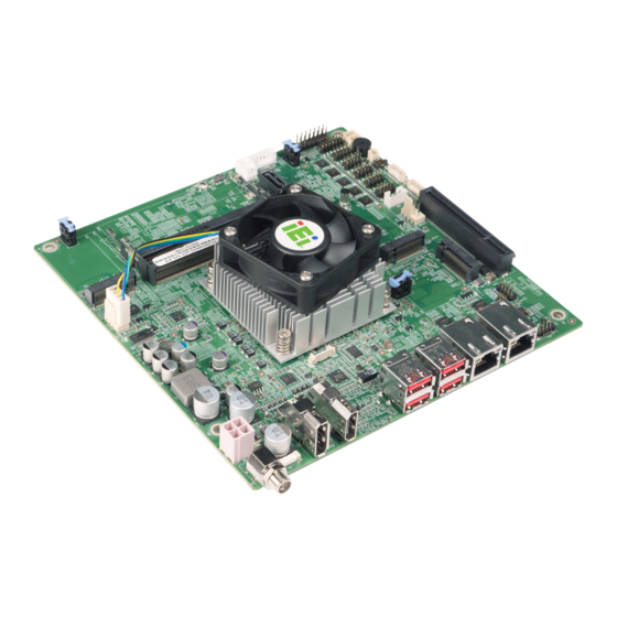
Mini-ITX SBC Supports 11
Processor (Tiger Lake-UP3 Mobile), 9V~36V DC Input, Quadruple
Independent Display, HDMI, DP, IEI eDP Module, SATA 6Gb/s,
Dual Intel® 2.5GbE, USB 3.2 Gen 2, M.2 and RoHS
Quick Installation Guide
Package List
KINO-TGL-U package includes the following items:
1 x KINO-TGL-U single board computer with CPU cooler
1 x SATA cable
1 x I/O shielding
1 x QIG
th
KINO-TGL-U
Version 1.0
February 21, 2022
© 2022 Copyright by IEI Integration Corp.
All rights reserved.
Gen Intel® Core™ i7/i5/i3 or Celeron®
Advertisement

Related Manuals for IEI Technology KINO-TGL-U


Summary of Contents for IEI Technology KINO-TGL-U
- Page 1 Quick Installation Guide Version 1.0 February 21, 2022 Package List KINO-TGL-U package includes the following items: 1 x KINO-TGL-U single board computer with CPU cooler 1 x SATA cable 1 x I/O shielding 1 x QIG ©...
-
Page 2: Specifications
Specifications CPU: Gen. Intel® mobile Tiger Lake-UP3 on-board processor: Intel® Core™ i7-1185G7E (up to 4.4GHz, quad-core, 12M cache, TDP=28/15/12W) Intel® Core™ i5-1145G7E (up to 4.1GHz, quad-core, 8M cache, TDP=28/15/12W) Intel® Core™ i3-1115G4E (up to 3.9GHz, dual-core, 6M cache, TDP=28/15/12W) Intel®... - Page 3 1 x RS-232/422/485 (2x5 pin, p=2.0) (support Auto Flow Control over RS-485) 1 x RS-422/485 (1x4 pin, p=2.0) (support Auto Flow Control over RS-485) 2 x SATA 6Gb/s Audio: 1 x IAUDIO connector supporting IEI AC-KIT-888S audio module (2x5 pin, p=2.0) ...
- Page 4 IEI Resource Download Center All the drivers and utility for the KINO- https://download.ieiworld.com TGL-U are available on IEI Resource Download Center. Type KINO-TGL-U and press Enter to find all the relevant software, utilities, and documentation. To install software from the downloaded ISO file, mount the file as a virtual drive to view its content.
-
Page 5: Ordering Information
Ordering Information KINO-TGL-U-i7-R10: Mini-ITX SBC supports 11th Gen Intel® Core™ i7-1185G7E processor, DDR4 SO-DIMM, 9V~36V DC input, quad display, SATA, dual Intel® 2.5GbE, USB 3.2, M.2, and RoHS KINO-TGL-U-i5-R10: Mini-ITX SBC supports 11th Gen Intel® Core™ i5-1145G7E processor, DDR4 SO-DIMM, 9V~36V DC input, quad display, SATA, dual Intel®... -
Page 6: Jumpers Setting And Connectors
Jumpers Setting and Connectors LABEL FUNCTION J_ATX_AT1 AT/ATX power mode setting J_CMOS1 Clear CMOS jumper ME_FLASH1 Flash descriptor security override jumper BAT1 RTC battery connector IAUDIO Internal audio connector for IEI audio module IDPM IEI IDPM slot (for IEI eDP/LVDS/VGA module) DIMM1, DIMM2 DDR4 SO-DIMM slots Internal power input connector... - Page 7 HDMI1 External HDMI connector External DisplayPort connector J_ATX_AT1: AT/ATX Power Mode Setting PIN NO. DESCRIPTION Short 1 - 2 ATX Power Mode (default) Short 2 - 3 AT Power Mode J_CMOS1: Clear CMOS Jumper Status DESCRIPTION Keep CMOS Setup (Normal Operation) Press button Clear CMOS Setup ME_FLASH1: Flash Descriptor Security Override Jumper...
- Page 8 DIO1 : Digital Input/Output Connector PIN NO. DESCRIPTION PIN NO. DESCRIPTION Output 5 Output 4 Output 3 Output 2 Output 1 Output 0 Input 5 Input 4 Input 3 Input 2 Input 1 Input 0 DEBUG_SPI1: EC Debug Connector PIN NO. DESCRIPTION PIN NO.
- Page 9 JSMB1: SMBus Connector PIN NO. DESCRIPTION PIN NO. DESCRIPTION SMB_CLK SMB_DATA F_PANEL1: Front Panel Connector DESCRIPTION DESCRIPTION PWR_LED+ BEEP_PWR SPKR PWR_LED- PWR_BTN+ PC_BEEP PWR_BTN- HDD_LED+ Reset+ RESET HDD_LED- Reset- JP1: LAN1 Link LED Connector DESCRIPTION DESCRIPTION +3.3V LAN1_LED_LNK#_ACT JP2: LAN2 Link LED Connector DESCRIPTION DESCRIPTION +3.3V...
- Page 10 COM5: RS-232/422/485 Serial Port Connector PIN NO. DESCRIPTION PIN NO. DESCRIPTION COM6: RS-422/485 Serial Port Connector PIN NO. RS-422 RS-485 RXD- RXD+ TXD+ DATA+ TXD- DATA- SATA1, SATA2: SATA 6Gb/s Connectors PIN NO. DESCRIPTION PIN NO. DESCRIPTION SATA_RX‐ SATA_TX+ SATA RX+ SATA_TX‐...
- Page 11 JBIOS1: Flash SPI ROM Connector PIN NO. DESCRIPTION PIN NO. DESCRIPTION +3.3V SPI_CLK SPI_CS# SPI_SI SPI_SO JEC2: Flash EC ROM Connector PIN NO. DESCRIPTION PIN NO. DESCRIPTION SPI_CS# +3.3V SPI_SO EC_DET_FLASH SPI_CLK SPI_SI USB2_CN1: Internal USB 2.0 Connector PIN NO. DESCRIPTION PIN NO.
- Page 12 DISPLAY_DETECT_ +3.3VS PIN23 +3.3VS EDP_TX3_DN +12VS EDP_TX3_DP +12VS +12VS EDP_TX2_DN +12VS EDP_TX2_DP SMB_CLK EDP_TX1_DN SMB_DATA EDP_TX1_DP EC_BKLT_CTRL EDP_TX0_DN EDP1_BKLT_CTRL EDP_TX0_DP EDP1_BKLT_EN EDP1_VDD_EN # EDP_AUX_DN EDP_HPD_R EDP_AUX_DP BUF_PLT_RST# LVDS_EN +V5S +V5S +V5S +V5S +12VA +12VA +12VA +12VA M2_AE1: M.2 A-key Slot PIN NO.
- Page 13 Module Key Module Key Module Key Module Key Module Key Module Key Module Key PCIE_TX+ PCIE_TX- CL_RST# CL_DATA PCIE_RX+ CL_CLK PCIE_RX- PCIE_CLK+ PCIE_CLK- BUF_PLT_RST Pull up +3.3V Pull up +3.3V +3.3V +3.3V...
- Page 14 M2_M1: M.2 M-key Slot PIN NO. DESCRIPTION PIN NO. DESCRIPTION +3.3V +3.3V +3.3V +3.3V +3.3V +3.3V +3.3V PCIE_RXN1 PCIE_RXP1 PCIE_TXN1 PCIE_TXP1 DEVSLP PCIE_RXN0 PCIE_RXP0 PCIE_TXN0 PCIE_TXP0 PERST# CLKREQ REFCLKN PEWAKE REFCLKP Module Key Module Key Module Key Module Key Module Key Module Key Module Key Module Key...
- Page 15 PEDET +3.3V +3.3V +3.3V LAN1, LAN2: External 2.5GbE RJ-45 Connectors PIN NO. DESCRIPTION PIN NO. DESCRIPTION MDIA3- MDIA1+ MDIA3+ MDIA2+- MDIA2- MDIA0- MDIA1- MDIA0+ DP1: External DisplayPort Connector PIN NO. DESCRIPTION PIN NO. DESCRIPTION LANE0P LANE3N LANE0N AUX_CTRL_DET_C LANE1P LANE1N AUXP LANE2P AUXN...
- Page 16 HDMI1: External HDMI Connector PIN NO. DESCRIPTION PIN NO. DESCRIPTION HDMI_DATA2 HDMI_CLK# HDMI_DATA2# HDMI_DATA1 HDMI_SCL HDMI_DATA1# HDMI_SDA HDMI_DATA0 HDMI_DATA0# HDMI_HPD HDMI_CLK USB_CON1, USB_CON2: External USB 3.2 Gen 2 Connectors PIN NO. DESCRIPTION PIN NO. DESCRIPTION USB_DATA- USB_DATA- USB_DATA+ USB_ DATA+ USB3_RX- USB3_RX- USB3_RX+...
- Page 17 Board Layout: Jumper and Connector Locations (Unit: mm)
Need help?
Do you have a question about the KINO-TGL-U and is the answer not in the manual?
Questions and answers