Sign In
Upload
Manuals
Brands
IEI Technology Manuals
Single board computers
KINO-DQM871-i1
IEI Technology KINO-DQM871-i1 Manuals
Manuals and User Guides for IEI Technology KINO-DQM871-i1. We have
1
IEI Technology KINO-DQM871-i1 manual available for free PDF download: User Manual
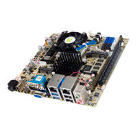
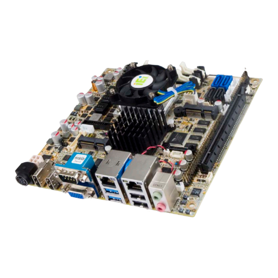
IEI Technology KINO-DQM871-i1 User Manual (160 pages)
Mini-ITX SBC
Brand:
IEI Technology
| Category:
Single board computers
| Size: 4.46 MB
Table of Contents
Table of Contents
5
1 Introduction
15
Introduction
16
Figure 1-1: KINO-DQM871-I1
16
Benefits
17
Features
17
Connectors
18
Figure 1-2: Connectors
18
Dimensions
19
Figure 1-3: KINO-DQM871-I1 Dimensions (MM)
19
Data Flow
20
Figure 1-4: Data Flow Diagram
20
Technical Specifications
21
Table 1-1: Technical Specifications
23
2 Packing List
24
Anti-Static Precautions
25
Unpacking Precautions
25
Packing List
26
Table 2-1: Packing List
26
Optional Items
27
Table 2-2: Optional Items
27
3 Connector Pinouts
28
Peripheral Interface Connectors
29
Layout
29
Figure 3-1: Connector and Jumper Locations
29
Peripheral Interface Connectors
30
External Interface Panel Connectors
31
Table 3-1: Peripheral Interface Connectors
31
Table 3-2: Rear Panel Connectors
31
Internal Peripheral Connectors
32
ATX Power Signal Connector
32
Figure 3-2: ATX Power Signal Connector Location
32
Table 3-3: ATX Power Signal Connector Pinouts
32
Battery Connector
33
Figure 3-3: Battery Connector Location
33
Chassis Intrusion Connector
34
Figure 3-4: Chassis Intrusion Connector Location
34
Table 3-4: Battery Connector Pinouts
34
Table 3-5: Chassis Intrusion Connector Pinouts
34
Digital I/O Connector
35
Displayport Connector
35
Figure 3-5: Digital I/O Connector Location
35
Table 3-6: Digital I/O Connector Pinouts
35
Figure 3-6: Displayport Connector Location
36
Table 3-7: Displayport Connector Pinouts
36
EC Debug Connector
37
Figure 3-7: BIOS Debug Port Location
37
Table 3-8: EC Debug Port Pinouts
37
Fan Connector (CPU)
38
Fan Connector (System)
38
Figure 3-8: CPU Fan Connector Location
38
Table 3-9: CPU Fan Connector Pinouts
38
Front Panel Connector
39
Figure 3-9: System Fan Connector Location
39
Table 3-10: System Fan Connector Pinouts
39
Iris Module Slot
40
Figure 3-10: Front Panel Connector Location
40
Table 3-11: Front Panel Connector Pinouts
40
IPMI Active LED Connector
41
Figure 3-11: Iris Module Slot Location
41
Keyboard/Mouse Connector
42
Figure 3-12: IPMI Active LED Connector
42
Table 3-12: IPMI Active LED Connector Pinouts
42
LAN Active LED Connector
43
Figure 3-13: Keyboard/Mouse Connector Location
43
Table 3-13: Keyboard/Mouse Connector Pinouts
43
LVDS Connector
44
Figure 3-14: LAN Active LED Connector Location
44
Table 3-14: LAN Active LED Connector Pinouts
44
Figure 3-15: LVDS Connector Location
45
Table 3-15: LVDS Connector Pinouts
45
LVDS Backlight Connector
46
Pcie Mini Card Slot
46
Figure 3-16: LVDS Backlight Inverter Connector
46
Table 3-16: Backlight Inverter Connector Pinouts
46
Figure 3-17: Pcie Mini Card Slot Location
47
PCI Express X16 Slot
48
Figure 3-18: Pcie X16 Slot Location
48
Table 3-17: Pcie Mini Card Slot Pinouts
48
Table 3-18: Pcie X16 Side a Pinouts
49
Power Button (On-Board)
50
Figure 3-19: On-Board Power Button Location
50
Table 3-19: Pcie X16 Side B Pinouts
50
Power Connector (12V)
51
Serial Port Connectors (COM2 ~ COM5)
51
Figure 3-20: Power Connector Location
51
Table 3-20: Power Connector Pinouts
51
Figure 3-21: RS-232 Serial Port Connector Location
52
Table 3-21: COM2 Pinouts
52
Table 3-22: COM3 Pinouts
52
RS-422/485 Serial Port Connector (COM6)
53
Table 3-23: COM4 Pinouts
53
Table 3-24: COM5 Pinouts
53
SATA 6Gb/S Drive Connectors
54
Figure 3-22: RS-422/485 Serial Port Connector Location
54
Table 3-25: RS-422/485 Serial Port Connector Pinouts
54
Table 3-26: D-Sub 9 RS-422/485 Pinouts
54
SATA 3Gb/S Drive Connectors
55
Figure 3-23: SATA 6Gb/S Drive Connector Locations
55
Table 3-27: SATA 6Gb/S Drive Connector Pinouts
55
SATA Power Connectors
56
Figure 3-24: SATA 3Gb/S Drive Connector Locations
56
Table 3-28: SATA 3Gb/S Drive Connector Pinouts
56
Smbus Connector
57
Figure 3-25: SATA Power Connector Locations
57
Table 3-29: SATA Power Connector Pinouts
57
SO-DIMM Connectors
58
Figure 3-26: Smbus Connector Location
58
Table 3-30: Smbus Connector Pinouts
58
SPI Flash Connector
59
Figure 3-27: SO-DIMM Connector Locations
59
SPI Flash Connector (EC)
60
Figure 3-28: SPI Flash Connector Location
60
Table 3-31: SPI Flash Connector Pinouts
60
TPM Connector
61
Figure 3-29: EC SPI Flash Connector Location
61
Table 3-32: EC SPI Flash Connector Pinouts
61
USB 2.0 Connectors
62
Figure 3-30: TPM Connector Location
62
Table 3-33: TPM Connector Pinouts
62
Figure 3-31: USB 2.0 Connector Locations
63
Table 3-34: USB1 Pinouts
63
Table 3-35: USB2 Pinouts
63
USB 3.2 Gen 1 Connector
64
Figure 3-32: USB 3.2 Gen 1 Connector Location
64
Table 3-36: USB3 Pinouts
64
External Interface Connectors
65
Audio Connector
65
Figure 3-33: External Interface Connectors
65
Table 3-37: USB 3.2 Gen 1 Connector Pinouts
65
Ethernet and USB 2.0 Connectors
66
Figure 3-34: Audio Jacks
66
Figure 3-35: Ethernet Connector
66
Table 3-38: LAN2 Pinouts
66
Ethernet and USB 3.2 Gen 1 Connectors
67
Table 3-39: Connector Leds
67
Table 3-40: External USB 2.0 Port Pinouts
67
Table 3-41: LAN1 Pinouts
67
HDMI Connectors
68
Figure 3-36: Ethernet Connector
68
Table 3-42: Connector Leds
68
Table 3-43: External USB 3.2 Gen 1 Port Pinouts
68
Power Connector (12 V, Power Adapter)
69
Figure 3-37: HDMI Connector
69
Table 3-44: HDMI Connector Pinouts
69
Serial Port Connector (COM1)
70
Figure 3-38: 4-Pin Power Mini-DIN Connection
70
Figure 3-39: Serial Port Pinouts
70
Table 3-45: Serial Port Pinouts
70
VGA Connector
71
Figure 3-40: VGA Connector
71
Table 3-46: VGA Connector Pinouts
71
4 Installation
72
Anti-Static Precautions
73
Installation Considerations
73
Cooling Kit Installation
75
Figure 4-1: Install Support Bracket
75
Figure 4-2: Align the Cooling Kit
76
So-DIMM Installation
77
Figure 4-3: Secure the Cooling Kit
77
Iris-1010 Module Installation
78
Figure 4-4: SO-DIMM Installation
78
Figure 4-5: Iris-1010 Module Installation
79
Pcie Mini Card Installation
80
Figure 4-6: Iris-1010 Module Installation
80
Jumper Settings
81
Figure 4-7: Pcie Mini Card Installation
81
AT/ATX Mode Selection
82
Table 4-1: Jumpers
82
Clear CMOS
83
Figure 4-8: AT/ATX Mode Selection Jumper Location
83
Figure 4-9: Clear CMOS Jumper Location
84
LVDS Voltage Selection
84
Table 4-2: LVDS Voltage Selection Jumper Settings
84
Figure 4-10: LVDS Voltage Selection Jumper Location
85
LVDS Resolution Selection
85
Chassis Installation
86
Airflow
86
Figure 4-11: LVDS Resolution Selection Jumper Location
86
Table 4-3: LVDS Resolution Selection Jumper Settings
86
Motherboard Installation
87
Internal Peripheral Device Connections
87
SATA Drive Connection
87
Figure 4-12: SATA Drive Cable Connection
87
Ipmi Setup Procedure
88
Intel ® Amt Setup Procedure
88
5 Bios
90
Introduction
91
Starting Setup
91
Using Setup
91
Getting Help
92
Unable to Reboot after Configuration Changes
92
Table 5-1: BIOS Navigation Keys
92
BIOS Menu Bar
93
Main
94
BIOS Menu 1: Main
94
Advanced
95
ACPI Settings
96
BIOS Menu 2: Advanced
96
BIOS Menu 3: ACPI Settings
96
RTC Wake Settings
97
BIOS Menu 4: RTC Wake Settings
97
Trusted Computing
98
BIOS Menu 5: Trusted Computing
99
CPU Configuration
100
BIOS Menu 6: CPU Configuration
100
SATA Configuration
102
BIOS Menu 7: SATA Configuration
102
Intel(R) Rapid Start Technology
103
BIOS Menu 8: Intel(R) Rapid Start Technology
103
AMT Configuration
104
BIOS Menu 9: AMT Configuration
104
USB Configuration
105
BIOS Menu 10: USB Configuration
105
Iwdd H/W Monitor
106
BIOS Menu 11: Iwdd H/W Monitor
106
BIOS Menu 12: Smar Fan Mode Configuration
107
Smart Fan Mode Configuration
107
F81866 Super IO Configuration
108
BIOS Menu 13: F81866 Super IO Configuration
108
BIOS Menu 14: Serial Port N Configuration Menu
109
Serial Port N Configuration
109
Serial Port Console Redirection
114
BIOS Menu 15: Serial Port Console Redirection
115
Iei Feature
118
BIOS Menu 16: Iei Feature
118
Chipset
119
BIOS Menu 17: Chipset
119
PCH-IO Configuration
120
BIOS Menu 18: PCH-IO Configuration
120
BIOS Menu 19: PCI Express Configuration
122
PCI Express Configuration
122
System Agent (SA) Configuration
123
Graphics Configuration
123
BIOS Menu 20: System Agent (SA) Configuration
123
BIOS Menu 21: Graphics Configuration
124
NB Pcie Configuration
126
BIOS Menu 22: NB Pcie Configuration
126
Memory Configuration
127
BIOS Menu 23: Memory Configuration
127
Boot
128
BIOS Menu 24: Boot
128
Security
130
Save & Exit
130
BIOS Menu 25: Security
130
BIOS Menu 26: Save & Exit
131
6 Software Drivers
132
Available Drivers
133
Driver Download
133
Figure 6-1: IEI Resource Download Center
133
A Regulatory Compliance
135
B Product Disposal
137
CBIOS Options
139
D Digital I/O Interface
142
E Watchdog Timer
145
F Address Mapping
148
Direct Memory Access (Dma)
149
Input/Output (IO)
150
Interrupt Request (Irq)
153
Memory
154
G Error Beep Code
156
Pei Beep Codes
157
Dxe Beep Codes
157
H Hazardous Materials Disclosure
158
Advertisement
Advertisement
Related Products
IEI Technology KINO-DAL-N1
IEI Technology KINO-DAL-N2
IEI Technology KINO-DAL-E3W2
IEI Technology KINO-DAL-E2W2
IEI Technology KINO-DAL-E1W2
IEI Technology KINO-DBT-J1900-R10
IEI Technology KINO-DBT-N29301-R10
IEI Technology KINO-DBT-N28071-R10
IEI Technology KINO-DBT-E38XX1-R10
IEI Technology KINO-DAL
IEI Technology Categories
Motherboard
Touch Panel
Computer Hardware
Single board computers
Desktop
More IEI Technology Manuals
Login
Sign In
OR
Sign in with Facebook
Sign in with Google
Upload manual
Upload from disk
Upload from URL