Advertisement
Quick Links
All manuals and user guides at all-guides.com
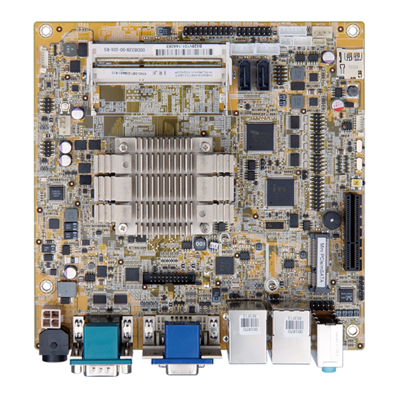
Mini-ITX SBC with Intel® 22nm Atom SoC processors, VGA / DVI-D /
iDP, USB 3.0, SATA, HD Audio, RoHS
Quick Installation Guide
Package List
KINO-DBT package includes the following items:
1 x KINO-DBT single board computer
1 x SATA cable with power output cable
1 x IO shielding (P/N: 45014-0056C0-00-RS)
1 x QIG (Quick Installation Guide)
1 x Utility CD
©2006 Copyright by IEI Integration corp.
KINO-DBT
Version 1.0
Feb 19, 2016.
All rights reserved.
1
Advertisement

Related Manuals for IEI Technology KINO-DBT


Summary of Contents for IEI Technology KINO-DBT
- Page 1 USB 3.0, SATA, HD Audio, RoHS KINO-DBT Quick Installation Guide Version 1.0 Feb 19, 2016. Package List KINO-DBT package includes the following items: 1 x KINO-DBT single board computer 1 x SATA cable with power output cable ...
-
Page 2: Specifications
All manuals and user guides at all-guides.com Specifications SoC: Intel® Atom™ E3845 on-board SoC (1.91GHz, quad-core, 2MB cache, TDP=10W) Intel® Atom™ E3827 on-board SoC (1.75GHz, dual-core, 1MB cache, TDP=8W) Intel® Atom™ E3826 on-board SoC (1.46GHz, dual-core, 1MB cache, TDP=7W) Intel®... - Page 3 All manuals and user guides at all-guides.com External I/O Interface: 2 x RS-232 2 x USB2.0 2 x USB3.0 Internal I/O Interface: 1 x KB/MS (1 x 6 pin) 1 x mSATA share with SATA port II 1 x RS-422/485 (1 x 4 pin, P=2.0) 2 x SATA 3Gb/s with 5V, 12 V SATA power connector 5 x RS-232 (2 x 5 pin, P=2.54) 4 x USB2.0 (2 x 4 pin, P=2.0)
-
Page 4: Ordering Information
Operation Humidity: 5% ~ 95%, non-condensing Dimensions: 170mm x 170mm Weight(GW/ NW): 900g/400g Ordering Information KINO-DBT-J1900-R10: Mini-ITX SBC supports Intel® Celeron® Quad-Core Processor J1900(10W), VGA/DVI/iDP, Dual Realtek® PCIe GbE, USB 3.0, SATA, HD Audio, RoHS ... - Page 5 All manuals and user guides at all-guides.com 32205-002700-100-RS: RS-232 CABLE ;2;200MM;D-SUB 9, 2*5P P=2.0 32006-000300-100-RS: PS/2 KB/MS Y-cable without bracket 32205-003800-300-RS: RS-422/485 cable, 200mm DP-LVDS-R10: DisplayPort to 24-bit dual-channel LVDS converter board (for IEI iDP connector) ...
-
Page 6: Jumpers Setting And Connectors
All manuals and user guides at all-guides.com Jumpers setting and connectors LABEL FUNCTION J_CMOS1 Clear CMOS J_ATX_AT1 AT/ATX Power Mode Setting USB SW1 Power USB Power Setting USB SW2 Power MSATA_SW1 MSATA Selection F_PANEL1 PWR & RST Buttons and indicators VIDEO1 VGA 15-pin Female Connector VIDEO1... - Page 7 All manuals and user guides at all-guides.com SMBUS Connector LED_LAN1 LAN1 LINK LED Connector LED_LAN2 LAN2 LINK LED Connector J_CMOS1: Clear CMOS button PIN NO. DESCRIPTION Keep CMOS Setup NC (default) (Normal Operation) Press button Clear CMOS Setup J_ATX_AT1: AT/ATX mode select switch PIN NO.
- Page 8 All manuals and user guides at all-guides.com MSATA_SW : MSATA setting PIN NO. DESCRIPTION Short 1 - 2 Auto detect M-SATA (default) Short 2 - 3 M-SATA Enable F_PANEL1: PWR & RST Buttons and indicators DESCRIPTION DESCRIPTION BEEP_PWR SPKR IPMI ID_LED+ IPMI LED IPMI ID_LED- PWRBTN_SW#...
- Page 9 All manuals and user guides at all-guides.com VIDEO1: DVI-I(Dual Link)+CRT PIN NO. DESCRIPTION PIN NO. DESCRIPTION DVI_DATA1 GREEN BLUE Hot Plug Detect DVI_DATA2# HPDET DVI_DATA2 DVI_DATA0# DVI_DATA0 DDC CLK DDC DATA DVI_CLK DVI_DATA1# DVI_CLK# DP1: Display port connector PIN NO. DESCRIPTION PIN NO.
- Page 10 All manuals and user guides at all-guides.com LAN1_USB1: RJ45 LAN and USB3.0 Connector USB3.0 Connector PIN NO. DESCRIPTION PIN NO. DESCRIPTION USB_DATA- USB_DATA- USB_DATA+ USB_ DATA+ USB3_RX- USB3_RX- USB3_RX+ USB3_ RX+ USB3_TX- USB3_TX- USB3_TX+ USB3_TX+ RJ45 LAN PIN NO. DESCRIPTION PIN NO.
- Page 11 All manuals and user guides at all-guides.com KB_MS1: Keyboard & mouse pin header PIN NO. DESCRIPTION PIN NO. DESCRIPTION Mouse Data Mouse Clock Keyboard Data Keyboard Clock USB1, USB2: Internal USB 2.0 connectors PIN NO. DESCRIPTION PIN NO. DESCRIPTION USB_DATA- USB_DATA+ USB_DATA+ USB_DATA-...
- Page 12 All manuals and user guides at all-guides.com COM4: RS-422/485 serial port connector DESCRIPTION DESCRIPTION RXD485# RXD485+ TXD485+ TXD485# AUDIO_CV1 : Audio Line-In/Out MIC Connector PIN NO. DESCRIPTION Line_In (Blue) CD/DVD or other audio source input port Line_Out (Green) Connect this port to headphone or speaker Microphone (Pink) Connect this port to microphone FRONT-PANEL1: Audio Source Connector...
- Page 13 All manuals and user guides at all-guides.com SATA1, SATA2: SATA 3Gb/s Drive Connectors PIN NO. DESCRIPTION PIN NO. DESCRIPTION SATA_RX- SATA_TX+ SATA RX+ SATA_TX- CPU_FAN1: CPU FAN connector PIN NO. DESCRIPTION PIN NO. DESCRIPTION +12V FANIO SYS_FAN1: System FAN connector PIN NO.
- Page 14 All manuals and user guides at all-guides.com CN8: Mini PCI-E Card Connector PIN NO. DESCRIPTION PIN NO. DESCRIPTION PCIE_WAKE# +3.3V 1.5V MSATA_CLK# MSATA _CLK PLTRST_N +3.3V PLTRST_N SATA_RX+ +3.3V SATA_RX- 1.5V SMB_CLK SATA_TX- SMB_DATA SATA_TX+ USB_DATA- USB_DATA+ +3.3V +3.3V +3.3V CLINK_CLK CLINK_DATA 1.5V...
- Page 15 All manuals and user guides at all-guides.com TPM1: TPM connector PIN NO. DESCRIPTION PIN NO. DESCRIPTION LCLK LFRAME# LRERST# LAD3 LAD2 +3.3V LAD1 LAD0 SB3V SERIRQ GLKRUN# LPCPD# LDRQ# SATA_PWR1,2 : Serial ATA Power Connector PIN NO. DESCRIPTION PIN NO. DESCRIPTION CN9: EC debug port PIN NO.
- Page 16 All manuals and user guides at all-guides.com JSPI1: Flash SPI ROM Connector PIN NO. DESCRIPTION PIN NO. DESCRIPTION +1.8V SPI_CS# SPI_SO SPI_CLK SPI_SI JSPI2: Flash EC ROM Connector PIN NO. DESCRIPTION PIN NO. DESCRIPTION +1.8V SPI_CS# SPI_SO SPI_CLK SPI_SI CN5: SMBUS Connector PIN NO.
- Page 17 All manuals and user guides at all-guides.com Board Layout: Jumper and Connector Locations ** E3825、E3815、N2807 僅有 DIMM1 上件 (Unit: mm)
Need help?
Do you have a question about the KINO-DBT and is the answer not in the manual?
Questions and answers