
Related Manuals for Pilz PIT es Set10u-5ns (AIDA) basic


Summary of Contents for Pilz PIT es Set10u-5ns (AIDA) basic
- Page 1 PIT es Set10u-5ns (AIDA) basic Control and signal devices Operating Manual-1004863-EN-03...
- Page 2 Preface This document is the original document. All rights to this documentation are reserved by Pilz GmbH & Co. KG. Copies may be made for the user's internal purposes. Suggestions and comments for improving this documenta- tion will be gratefully received.
-
Page 3: Table Of Contents
Examples for connection to Pilz evaluation devices ..............Faults/interference ......................... Care and maintenance ......................Dimensions in mm ......................... Technical details ........................Safety characteristic data ......................Supplementary data ......................Permitted operating height......................Order reference ........................Product ............................. Accessories ..........................Operating Manual PIT es Set10u-5ns (AIDA) basic 1004863-EN-03... - Page 4 Contents Mounting bracket ........................Open-ended connection cable....................Connection cable for connection to decentralised modules ............. EC declaration of conformity ....................Operating Manual PIT es Set10u-5ns (AIDA) basic 1004863-EN-03...
-
Page 5: Introduction
PIT es Set10u-5ns (AIDA) basic Introduction Validity of documentation This documentation is valid for the product PIT es Set10u-5ns (AIDA) basic. It is valid until new documentation is published. This operating manual explains the function and operation, describes the installation and provides guidelines on how to connect the product. -
Page 6: Overview
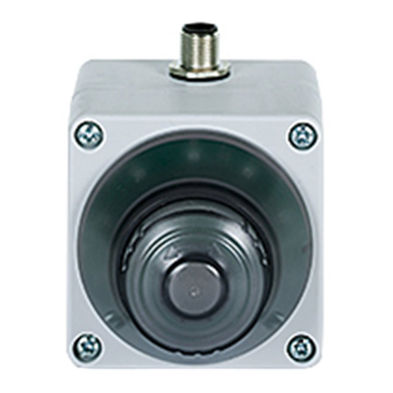
Integral flashing function of the yellow bevelled protective collar after operating the E- STOP pushbutton Connection to an evaluation device via 5-pin M12 connector Marking on E-STOP pushbutton Legend [1] Order number [2] Date of manufacture mmyy Operating Manual PIT es Set10u-5ns (AIDA) basic 1004863-EN-03... -
Page 7: Safety
The E-STOP function is triggered by operating the active E-STOP device and the voltage to the evaluation device is interrupted (dual-channel, fully operated). In active state, the E-STOP device PIT es Set10u-5ns (AIDA) basic is lit (the actuator lights up red) and it fulfils the requirements in accordance with EN ISO 13850. -
Page 8: Safety Regulations
In order to achieve the re- quired safety level for the overall plant/machine, define the safety requirements for the plant/machine and then define how these must be implemented from a technical and organ- isational standpoint. Operating Manual PIT es Set10u-5ns (AIDA) basic 1004863-EN-03... -
Page 9: Use Of Qualified Personnel
The unit meets all the necessary conditions for safe operation. However, please note the following: Check the function of the pushbutton before commissioning for the first time and then at regular intervals (at least annually). Operating Manual PIT es Set10u-5ns (AIDA) basic 1004863-EN-03... -
Page 10: Block Diagram/Terminal Configuration
Active: The E-STOP device is electrically supplied and it is not operated. The actuator is illuminated red, the bevelled protective collar is illuminated yellow. Inactive: The E-STOP device is not electrically supplied and it is therefore not illumin- ated. Operating Manual PIT es Set10u-5ns (AIDA) basic | 10 1004863-EN-03... -
Page 11: Installation
Use M4 screws to attach the housing subplate. Use an appropriate screw adhesive (e.g. Loctite) to protect the screws from working loose. Place the housing faceplate back on the housing subplate and screw them in place. Operating Manual PIT es Set10u-5ns (AIDA) basic | 11 1004863-EN-03... - Page 12 Make sure that no foreign bodies enter the housing during installation. NOTICE Before closing the housing, check that the seal is fitted correctly and ensure that the housing screws have a torque setting of 1.2 Nm. Operating Manual PIT es Set10u-5ns (AIDA) basic | 12 1004863-EN-03...
-
Page 13: Wiring
E-STOP devices that have only N/C contacts. Note that when operating a conventional E-STOP device which is in the chain before the PIT es Set10u-5ns (AIDA) basic, the PIT es Set10u-5ns (AIDA) basic is not electrically supplied and therefore it is not illuminated. -
Page 14: Requirements And Connection To Evaluation Devices
PIT es Set10u-5ns (AIDA) basic Requirements and connection to evaluation devices For use of PIT es Set10u-5ns (AIDA) basic an evaluation device must be connected. Connect the PIT es Set10u-5ns (AIDA) basic either with a Pilz evaluation device or with an evaluation device with defined properties (see section Defined properties of... -
Page 15: Examples For Connection To Pilz Evaluation Devices
PIT es Set10u-5ns (AIDA) basic To connect a decentralised module (e.g. PDP67 F 8DI ION from Pilz), use a 5-pin unshiel- ded cable with an A-coded M12 male connector (for connection to the decentralised mod- ule) and an A-coded M12 female connector (for connection to the E-STOP device) (see der reference [ "Connection cable for connection to decentralised modules"). -
Page 16: Faults/Interference
E-STOP pushbutton is still clearly visible, however at least once per year as part of the function test. Dust, soot and other deposits have an influence on brightness. If necessary, the E-STOP pushbutton must be cleaned or the device must be exchanged. Operating Manual PIT es Set10u-5ns (AIDA) basic | 16 1004863-EN-03... -
Page 17: Dimensions In Mm
PIT es Set10u-5ns (AIDA) basic Dimensions in mm 19.8 Mounting bracket (order no. 400 220) 82.3 14.5 Operating Manual PIT es Set10u-5ns (AIDA) basic | 17 1004863-EN-03... -
Page 18: Technical Details
Airgap creepage In accordance with the standard EN 60947-5-1 EN 60947-5-1 Overvoltage category Pollution degree Rated insulation voltage 50 V 50 V Rated impulse withstand voltage 0,5 kV 0,5 kV Operating Manual PIT es Set10u-5ns (AIDA) basic | 18 1004863-EN-03... -
Page 19: Safety Characteristic Data
Please note that the Performance Level in accordance with EN 13849-1 can be reduced because of reduced fault detection when several E-STOP devices are cascaded. NOTICE Only one PIT es Set10u may be used per circuit (no cascading). Operating Manual PIT es Set10u-5ns (AIDA) basic | 19 1004863-EN-03... -
Page 20: Supplementary Data
5-pin M12 plug connection - AIDA PIN assignment; 2 N/C (push- in technology connection) Emergency stop pushbutton Product type Features Order no. PIT es10u E-STOP pushbutton can be activated/deactivated without logo and 400 540 without E-STOP symbol Operating Manual PIT es Set10u-5ns (AIDA) basic | 20 1004863-EN-03... -
Page 21: Accessories
50 m M12, 5-pin fe- 630 364 M12 5-pole 50m male con- nector, straight PSEN op cable 50 m M12, 5-pin fe- 630 365 angle M12 5-pole male con- nector, angled Operating Manual PIT es Set10u-5ns (AIDA) basic | 21 1004863-EN-03... - Page 22 European Parliament and of the Council. The complete EC Declaration of Conformity is available on the Internet at www.pilz.com/downloads. Authorised representative: Norbert Fröhlich, Pilz GmbH & Co. KG, Felix-Wankel-Str. 2, 73760 Ostfildern, Germany Operating Manual PIT es Set10u-5ns (AIDA) basic...
Need help?
Do you have a question about the PIT es Set10u-5ns (AIDA) basic and is the answer not in the manual?
Questions and answers