
Related Manuals for Pilz PSSu K S 16DO 0.5


Summary of Contents for Pilz PSSu K S 16DO 0.5
- Page 1 PSSu K S 16DO 0.5 Decentralised system PSSuniversal I/O Operating Manual 22059-EN-08...
- Page 2 Preface This document is a translation of the original document. All rights to this documentation are reserved by Pilz GmbH & Co. KG. Copies may be made for internal purposes. Suggestions and comments for improving this documentation will be gratefully received.
-
Page 3: Table Of Contents
Install labelling bracket Section 6 Wiring General wiring guidelines 6.1.1 Connectors' mechanical connection 6.1.2 Connect/disconnect the cables Terminal configuration Connecting the module Section 7 Operation Messages Display elements 7.2.1 Display elements for module diagnostics Operating Manual PSSu K S 16DO 0.5 22059-EN-08... - Page 4 Contents 7.2.2 Display elements for output status Section 8 Technical details Section 9 Order reference Product Accessories Operating Manual PSSu K S 16DO 0.5 22059-EN-08...
-
Page 5: Introduction
Introduction Introduction Validity of documentation This documentation is valid for the product PSSu K S 16DO 0.5. It is valid until new docu- mentation is published. This operating manual explains the function and operation, describes the installation and provides guidelines on how to connect the product. -
Page 6: Definition Of Symbols
It also highlights areas within the text that are of particular import- ance. INFORMATION This gives advice on applications and provides information on special fea- tures. Operating Manual PSSu K S 16DO 0.5 22059-EN-08... -
Page 7: Overview
2 x 10-pin connector strip Communication via: – Standard fieldbus For standard applications in system environment A and B Accessories: Connector with spring-loaded terminals (necessary for operation) Labelling bracket Labelling strips (sheets) Operating Manual PSSu K S 16DO 0.5 22059-EN-08... -
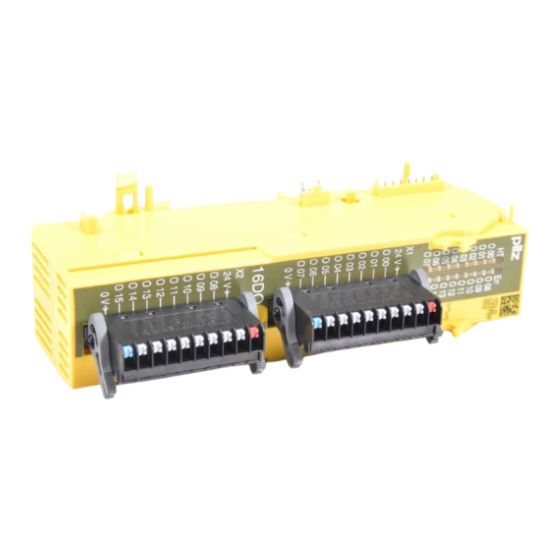
Page 8: Front View
3: Connector strip X1 for connectors with spring-loaded terminals 4: Connector strip X2 for connectors with spring-loaded terminals 5: Labelling strip for connector strip X2 6: Labelling strip for connector strip X1 7: LEDs for status display and module diagnostics Operating Manual PSSu K S 16DO 0.5 22059-EN-08... -
Page 9: Safety
Inductive loads Capacitive loads The module PSSu K S 16DO 0.5 may be used as a safety component in accordance with the Lifts Directive 95/16/EC, EN 81-1, EN 81-2 and EN 115-1. The programmable safety system should be installed in a protected environment that meets at least the requirements of pollution degree 2. -
Page 10: Safety Regulations
In safety-related applications, please comply with the mission time T in the safety-re- lated characteristic data. When decommissioning, please comply with local regulations regarding the disposal of electronic devices (e.g. Electrical and Electronic Equipment Act). Operating Manual PSSu K S 16DO 0.5 22059-EN-08... -
Page 11: Function Description
The Periphery Supply is not provided via the module bus, but it has to be fed via the connectors. The periphery supply is used to supply the outputs. Outputs The head module sets the output status via the module bus. Operating Manual PSSu K S 16DO 0.5 22059-EN-08... -
Page 12: Integrated Protection Mechanisms
PSSu assignment in system environment B Data access is via pre-defined I/O data types: I/O data name I/O data type I/O data element Meaning O00 … O15 ST_O_DO Data: BOOL Output data O00 ... O15 Operating Manual PSSu K S 16DO 0.5 22059-EN-08... -
Page 13: Installation
5.1.1 Dimensions Module with connector: 62,7 mm (2.469") 30 mm 49,2 mm (1.181") (1.937") Operating Manual PSSu K S 16DO 0.5 22059-EN-08... - Page 14 Installation Module with connector and labelling bracket: 30 mm 76,7 mm (1.181") (3.020") Operating Manual PSSu K S 16DO 0.5 22059-EN-08...
-
Page 15: Install Compact Module
– On the mounting rail, carefully slide the compact module to the left, in parallel to the adjoining module, until you hear the lateral mounting hooks on the adjacent module lock into position [4]. Operating Manual PSSu K S 16DO 0.5 22059-EN-08... - Page 16 Installation Schematic representation: Operating Manual PSSu K S 16DO 0.5 22059-EN-08...
-
Page 17: Install/Uninstall Connector
Schematic representation: Uninstallation procedure: Push both locking levers to the left, as far as they will go [1]. INFORMATION This will automatically lift the connector, which can then be removed from the module. Operating Manual PSSu K S 16DO 0.5 22059-EN-08... - Page 18 Installation NOTICE As you remove the connector, grasp the connector housing and not the cable harness. Schematic representation: Operating Manual PSSu K S 16DO 0.5 22059-EN-08...
-
Page 19: Install Labelling Bracket
We recommend that the labelling strips are attached to the labelling bracket prior to in- stallation. Slot the two pins on the labelling bracket into the receiving lugs on the module [1]. Check that the labelling bracket is firmly seated. Schematic representation: Operating Manual PSSu K S 16DO 0.5 22059-EN-08... -
Page 20: Wiring
Check that the cable is firmly seated [3]. Disconnect cable: Using the screwdriver, press the actuator button down as far as it will go [4], keep it held down and pull the cable out of the plug connection [4]. Operating Manual PSSu K S 16DO 0.5 22059-EN-08... - Page 21 Wiring Fig.: Connect and disconnect the cables Operating Manual PSSu K S 16DO 0.5 22059-EN-08...
-
Page 22: Terminal Configuration
O 09: Output 9 O 10: Output 10 O 11: Output 11 O 12: Output 12 O 13: Output 13 O 14: Output 14 O 15: Output 15 0 V: 0 V (external periphery supply) Operating Manual PSSu K S 16DO 0.5 22059-EN-08... - Page 23 O 10: Output 10 O 11: Output 11 O 12: Output 12 O 13: Output 13 O 14: Output 14 O 15: Output 15 0 V: 0 V (external periphery supply) Operating Manual PSSu K S 16DO 0.5 22059-EN-08...
-
Page 24: Connecting The Module
PSSu A Con 1/10 C PSSu A Con 3/30 C Single-wire technology 24 V 24 V O 01 O 05 Two-wire technology 24 V O 05 Three-wire technology 24 V O 05 Operating Manual PSSu K S 16DO 0.5 22059-EN-08... -
Page 25: Operation
Ensure there is sufficient ventila- Error stack entry tion in the control cabinet or pre- vent overload. Further information on PSSu error messages is available in the online help for the PSSuni- versal Assistant system software. Operating Manual PSSu K S 16DO 0.5 22059-EN-08... -
Page 26: Display Elements
Each output is assigned an LED for displaying the output status (LEDs “O 00 … O 15”). Meaning Designa- Colour Status Signal tion O 00 - - - 0 signal Green 1 signal O 15 Operating Manual PSSu K S 16DO 0.5 22059-EN-08... -
Page 27: Technical Details
Max. processing time of semiconductor output when signal changes from "0" to "1" 0,010 ms Potential isolation from system voltage Short circuit-proof Environmental data Climatic suitability EN 60068-2-1, EN 60068-2-14, EN 60068-2-2, EN 60068-2-30, EN 60068-2-78 Operating Manual PSSu K S 16DO 0.5 22059-EN-08... - Page 28 Front Labelling bracket (accessories) Mounting type plug-in Conductor cross section with spring-loaded terminals: Flexible with/without crimp connector 0,20 - 1,00 mm², 22 - 18 AWG Spring-loaded terminals: Terminal points per connec- tion Operating Manual PSSu K S 16DO 0.5 22059-EN-08...
- Page 29 Width 30,0 mm Depth 56,0 mm Depth incl. connector (accessories) 69,5 mm Depth incl. labelling bracket (accessories) 83,5 mm Weight 88 g Where standards are undated, the 2005-04 latest editions shall apply. Operating Manual PSSu K S 16DO 0.5 22059-EN-08...
-
Page 30: Order Reference
PSSu A LC 0.1 Labelling bracket, scope of supply: 5 pieces 312 966 PSSu A LA0 Labelling strips, laser printable, scope of supply: 1080 pieces 312 958 (10 x DIN A4 sheet, 108 on each) Operating Manual PSSu K S 16DO 0.5 22059-EN-08... - Page 31 Front cover Support Technical support is available from Pilz round the clock. Americas Australia Scandinavia Brazil +61 3 95446300 +45 74436332 +55 11 97569-2804 Spain Canada Europe +34 938497433 +1 888-315-PILZ (315-7459) Austria Switzerland Mexico +43 1 7986263-0 +41 62 88979-30...
Need help?
Do you have a question about the PSSu K S 16DO 0.5 and is the answer not in the manual?
Questions and answers