Table of Contents
Advertisement
Quick Links
Advertisement
Table of Contents

Related Manuals for Pilz PMCprotego S1-2


Summary of Contents for Pilz PMCprotego S1-2
- Page 1 PMCprotego S12(C) PMCprotego Safe Motion Operating Manual1002528EN03...
- Page 2 Preface This document is the original document. All rights to this documentation are reserved by Pilz GmbH & Co. KG. Copies may be made for internal purposes. Suggestions and comments for improving this documentation will be gratefully received. Pilz®, PIT®, PMI®, PNOZ®, Primo®, PSEN®, PSS®, PVIS®, SafetyBUS p®, SafetyEYE®, SafetyNET p®, the spirit of safety® are registered and protected trademarks of Pilz GmbH & Co. KG in some countries. SD means Secure Digital...
-
Page 3: Table Of Contents
Content Section 1 Introduction Validity of documentation 1.1.1 Retaining the documentation Definition of symbols Section 2 Overview Unit structure 2.1.1 Unit features Front view Section 3 Safety Intended use 3.1.1 Permitted motor types 3.1.2 Permitted motor encoder types 3.1.3 Use of qualified personnel 3.1.4 Warranty and liability 3.1.5 Disposal Standards Section 4 Function description Overview Inputs and outputs 4.2.1 Inputs 4.2.2 Outputs 4.2.2.1 Singlepole outputs 4.2.2.2 Dualpole outputs 4.2.2.3 Output test Safety functions 4.3.1... - Page 4 Content Section 6 Wiring General wiring guidelines Connector pin assignment Shielding Digital inputs Digital outputs 6.5.1 Supply voltage 6.5.2 Singlepole outputs 6.5.3 Dualpole outputs Encoder 6.6.1 Supply voltage 6.6.2 Incremental encoder with TTL signal 6.6.3 Absolute encoder with SSI interface Section 7 Commissioning Safety guidelines Initial commissioning Recommissioning 7.3.1 Recommissioning at a restart 7.3.2 Recommissioning after error 7.3.2.1 Switching the inputs "SS1 Activate" or "SS1 SIL3/Reset" 7.3.2.2 Command "CLRFAULT" 7.3.3 Swap safety card 7.3.3.1 Download configuration from Configurator to safety card 7.3.3.2 Download configuration to SD card 7.3.3.3 Download configuration from SD card to safety card Safety checks...
-
Page 5: Introduction
Introduction Introduction Validity of documentation This documentation is valid for the products PMCprotego S12 and PMCprotego S12C. It is valid until new documentation is published. This operating manual explains the function and operation, describes the installation and provides guidelines on how to connect the product PMCprotego S12(C). Please also refer to the following documents from the motion control range: The configuration of the expansion card is described in the online help for the Configur ator PASconfig SDrive. The servo amplifier PMCprotego D is described in the "PMCprotego D operating manual". Details of how to set the parameters for the servo amplifier are described in the help for the commissioning software PASmotion. All these manuals can be found on the supplied CDROM: "Motion Control" You will need to be conversant with the information in these documents in order to fully un derstand this manual. 1.1.1 Retaining the documentation This documentation is intended for instruction and should be retained for future reference. Definition of symbols Information that is particularly important is identified as follows: DANGER! This warning must be heeded! It warns of a hazardous situation that poses an immediate threat of serious injury and death and indicates preventive measures that can be taken. WARNING! This warning must be heeded! It warns of a hazardous situation that could lead to serious injury and death and indicates preventive measures that can be taken. Operating Manual PMCprotego S12(C) 1002528EN03... - Page 6 Introduction CAUTION! This refers to a hazard that can lead to a less serious or minor injury plus material damage, and also provides information on preventive measures that can be taken. NOTICE This describes a situation in which the product or devices could be dam aged and also provides information on preventive measures that can be taken. It also highlights areas within the text that are of particular import ance. INFORMATION This gives advice on applications and provides information on special fea tures. Operating Manual PMCprotego S12(C) 1002528EN03...
-
Page 7: Overview
Overview Overview Unit structure The safety card PMCprotego S12(C) is an expansion of the servo amplifier PMCprot ego D. It is used for safe motion monitoring, which is achieved in conjunction with the standard motor encoder and servo amplifier. In the event of an error, the servo amplifier's power element shuts down the power quickly and safely. 2.1.1 Unit features The safety card has the following features: 2 singlepole digital inputs to activate the safety function Safe Stop 1 (SS1) in accordance with EN 6180052 (fixed assignment): Safety function Safe Stop 1 (SS1) Input to achieve SIL3 and to reset the safety card after an error 7 singlepole digital inputs, which can be assigned the following safety functions in accord ance with EN 6180052 in the safety cards's Configurator: Safe Stop 2 (SS2) Safe Operating Stop (SOS) Safe Speed Range (SSR) Safely Limited Speed (SLS) Safe Direction (SDI) Safe Brake Test (SBT) (not defined in EN 6180052) Safely Limited Increment (SLI) Safely Limited Position (SLP) 3 singlepole digital outputs with fixed function: Safe Torque Off (STO) Safety card ready Second shutdown route (STO SIL3) 4 singlepole digital outputs, which can be freely assigned the status of safety functions. 1 dualpole digital output for Safe Brake Control (SBC) 1 input for incremental encoder or encoder with SSI signal Supply voltage 24 VDC for digital outputs LEDs for Supply voltage (POWER) System status (RUN) Download of configuration data (CONFIG) Fault or drive torquefree (STO) Operating Manual PMCprotego S12(C) 1002528EN03... -
Page 8: Front View
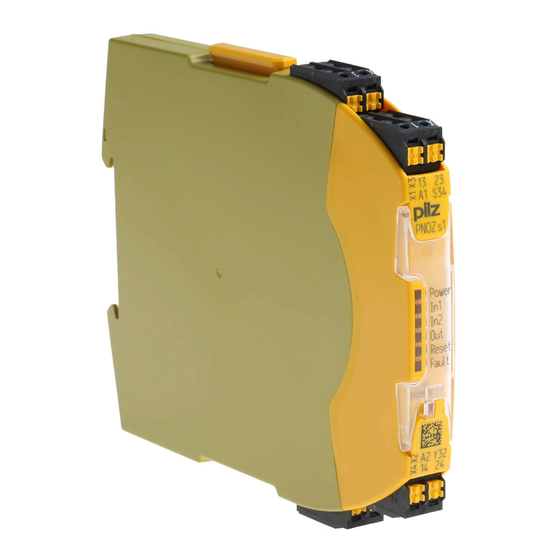
Overview C type: PMCprotego S12C: Coated circuit board Front view POWER CONFIG 8176105 12 100001 Key: 1: Screw for attachment to the servo amplifier 2: LEDs to display operating states 3: Inputs/outputs and supply voltage 4: Labelling strip with: – Order number – Serial number – Number of device version 5: 2D code 6: Connection for encoder Operating Manual PMCprotego S12(C) 1002528EN03... -
Page 9: Safety
Safety Safety Intended use The safety card PMCprotego S12(C) is an expansion of the servo amplifier PMCprot ego D. It is designed for use in safetyrelated applications. It meets the requirements for safety functions in accordance with EN 6180052, with re gard to safe motion monitoring. The safety card meets the requirements of EN IEC 61508 up to SIL 3 and EN ISO 138491 up to PL e. To achieve category SIL 3 or PL e, the operator must ensure that the function of the safe pulse disabler is tested periodically, after 8 hours at the latest, by triggering safety functions SS1 or STO: By restarting after safety functions SS1 or STO have been triggered as a condition of operation By restarting after safety function SS1 has been triggered by the operator INFORMATION To test the safe pulse disabler through deliberate operator action, see the section entitled "Operation", under "Testing the safe pulse disabler". The following is deemed improper use: Any component, technical or electrical modification to the servo amplifier Use of the servo amplifier outside the areas described in this manual Use of the servo amplifier outside the documented technical details (see chapter en titled “Technical Details”) Intended use includes making the installation and wiring EMCcompliant. Intended use also includes compliance with the Operating manual for the PMCprotego D Online help for the configuration tool PASconfig SDrive. INFORMATION For the use of the safety card in a PMCprotego D, the approvals of the rel evant servo amplifier apply (see Technical Details in the operating manual of the servo amplifiers). The safety card PMCprotego S12(C) from Version 1.0 may only be used in conjunction with the following servo amplifiers: PMCprotego D.01 from Version 1.1 PMCprotego D.03 from Version 1.1 PMCprotego D.06 from Version 1.1 Operating Manual PMCprotego S12(C) 1002528EN03... -
Page 10: Permitted Motor Types
Safety PMCprotego D.12 from Version 1.1 PMCprotego D.24 from Version 1.1 PMCprotego D.48 from Version 1.1 PMCprotego D.72 from Version 1.1 3.1.1 Permitted motor types The following motor types are approved for use with the safety card: Rotary synchronous motors Linear synchronous motors Please note: The use of synchronous motors without motor encoder (sensorless operation) is not permitted. Work is in progress for use with: Asynchronous motors Please note the following fault detection guidelines: When the drive is operated with an encoder (standard motor encoder on the servo ampli fier), a fault on the encoder system is detected by the safety card as follows: Rotary synchronous motors Detected within one mechanical revolution of the motor. Linear synchronous motors Detected within the distance travelled, in accordance with the following formula: Distance = (Number of poles /2) · Pole pair pitch Commands in the servo amplifier: – Number of poles: MPOLES – Pole pair pitch: MPITCH 3.1.2 Permitted motor encoder types The motor encoder is connected to an input on the servo amplifier. The following motor en coder types are approved for use with the safety card: Feedback type (parameter FBTYPE) in the servo amplifier's Connection to Status for opera commissioning the servo ampli tion with safety Encoder type software fier... -
Page 11: Use Of Qualified Personnel
Safety Feedback type (parameter FBTYPE) in the servo amplifier's Connection to Status for opera commissioning the servo ampli tion with safety Encoder type software fier card ROD 24V with W&S Enabled ROD 5V with W&S Enabled BiSS encoder 5 V digital Enabled BiSS encoder 12 V digital Enabled Enabled SSI Linear encoder Enabled ROD 5V Enabled EnDat 2.2 with 5 V Enabled EnDat 2.2 with 12 V Enabled 3.1.3 Use of qualified personnel The products may only be assembled, installed, programmed, commissioned, operated, maintained and decommissioned by competent persons. A competent person is someone who, because of their training, experience and current pro fessional activity, has the specialist knowledge required to test, assess and operate the work equipment, devices, systems, plant and machinery in accordance with the general standards and guidelines for safety technology. It is the company’s responsibility only to employ personnel who: Are familiar with the basic regulations concerning health and safety / accident preven... -
Page 12: Standards
Safety Standards Knowledge of and compliance with the relevant standards and directives are a prerequisite for using the safety card. The following standards are relevant: EN 6132631:2008: Electrical equipment for measurement, control and laboratory use EMC requirements EN 618003:2004: Adjustable speed electrical drives EN 6180052:2007: Adjustable speed electrical power drive systems – Part 52: Safety requirements. Functional EN ISO 138491:2008: Safety of machinery – Safetyrelated parts of control systems – Part 1: General principles for design, Part 2: Validation EN 61508:1998: Functional safety of safetyrelated electrical/electronic/programmable electronic control systems, Parts 1, 3, 4 EN 615082:2000: Requirements for safetyrelated electrical/electronic/programmable electronic systems EN 602041:2007: Safety of machinery – Electrical equipment of machines – Part 1: General requirements EN 62061:2005: Safety of machinery – Functional safety of safetyrelated electrical, electronic and programmable electronic control systems Please note this is not an exhaustive list of safety standards and directives. Operating Manual PMCprotego S12(C) 1002528EN03... -
Page 13: Function Description
Function description Function description Overview The safety card monitors safety functions in accordance with EN 6180052. It monitors safe motion sequences on drives, which are safely brought to a stop and shut down in the event of an error. The safety card is built into a servo amplifier PMCprotego D. This converts the servo ampli fier into a safe servo amplifier. A safe drive system from Pilz consists of the following: Servo amplifier (PMCprotego D) Safety card PMCprotego S built into the servo amplifier Servo motor (synchronous motor) with – Standard encoder system (feedback) – Brake (optional, not safetyrelated)) Safety control system Configurator PASconfig SDrive Safety control system Safe servo amplifier PMCprotego DS Servo amplifier Safety card PNOZmulti PMCprotego D PMCprotego S Digital inputs: Safety functions... -
Page 14: Inputs And Outputs
Function description The safety card Activates safety functions Monitors safe motion sequences. Signals the status of safety functions to the safety control system In the event of an error, activates the safe pulse disabler which is integrated within the servo amplifier and shuts down the power to the motor Passes the brake command to the servo amplifier that is executing the travel command Has a second shutdown route in order to implement categories SIL3 or PL e. Has a dualpole output to control an external holding brake. The brake can be tested using the safety function "safe brake test SBT". Has a connection for an external encoder (incremental encoder or encoder with SSI signals can be selected). For details of the safetyrelated assessment when using an external encoder see Chapter 8 "Technical Details", under "Safetyrelated characteristic data". The servo amplifier Removes the power to the motor, if the safe pulse disabler is activated, switches the motor to torquefree and can also control an internal motor brake. The safety control system Activates the safety functions via inputs on the safety card Evaluates signals from safety devices, such as: – ESTOP pushbuttons – Safety gates – Light beam devices – Twohand buttons Processes the safety card's status outputs Safe interconnection between safety card and safety control system Fault detection (shorts across contacts, short circuits) on signals between the safety control system and safety card, and initiation of measures Configurator PASconfig SDrive Configuration and parameterisation of the safety card Safe upload and download of the configuration file Online display of the status of the safety functions Display of error stack Ability to save the configuration to SD card Inputs and outputs The safety card has safe inputs and outputs which can be freely assigned can be assigned fixed functions. -
Page 15: Inputs
Function description Inputs and outputs are assigned to the safety functions in the safety card's Configurator. Inputs Safety Functions Outputs STO Acknowledge SS1 Activate STO SIL 3 SS1 SIL3/Reset Ready SS2 Activate SSA Safe Standstill Acknowledge SOS Activate SSA Safe Standstill Acknowledge SLS Activate SRA Safe Range Acknowledge SSR Activate SRA Safe Range Acknowledge SDI Pos Activate SDA Safe Direction Acknowledge SDI Neg Activate... -
Page 16: Outputs
Function description “1” signal (+24 V) at the input: – Safety function is not activated NOTICE Inputs "SS1 Activate" and "SS1 SIL3/Reset" must always be connected. In the case of all inputs, only tested outputs from a safety control system may be connected. 4.2.2 Outputs 4.2.2.1 Singlepole outputs Safe, singlepole outputs signal the status of the activated safety functions and the safety card's state of readiness. Outputs with fixed assignment: STO Acknowledge – 1: Power element switched off – Internal error on servo amplifier or safety card – Limit values exceeded – Activated via SS1 – 0: Drive in closed loop operation STO SIL3 – 1: Second shutdown route on – 0: Second shutdown route off Ready – 1: Safety card is ready for operation – 0: Safety card is not ready for operation. Possible causes: – Safety card is starting up – No supply voltage – Major internal error – Error on the feedback output "STO Acknowledge" INFORMATION "Ready" is a second feedback channel for the safety function STO. The "Ready" output switches off if a problem occurs at the feedback signal "STO Acknowledge". - Page 17 Function description INFORMATION If the "STO SIL3" output is not used, 24 VDC must be applied to the "STO2 ENABLE" input on the servo amplifier. The singlepole digital outputs O0 … O3 signal the status of the safety functions. Outputs are assigned to the signals in the safety card's Configurator. The following signals are avail able: SSA Safe Standstill Acknowledge – 1: Motor is within the permitted limit values for standstill. – 0: Standstill monitoring is inactive or motor is outside the standstill range SDA Safe Direction Acknowledge – 1: Drive is moving in the permitted direction. – 0: Drive is not moving in the permitted direction or monitoring is not activated. SRA Safe Range Acknowledge – 1: Drive is moving within the permitted limit values for speed or position. – 0: Drive is moving outside the permitted limit values for speed or position, or monit oring is not activated. SBA Safe Brake Acknowledge – 1: Brake test was run within the defined period – 0: Brake test must be activated within a selectable time period, otherwise the axis is shut down. The table below shows which outputs signal the status of which safety function. In No safety ternal function ac Output error tivated STO Acknowledge x SSA Safe Stand ...
-
Page 18: Dualpole Outputs
Function description – Current is supplied to the load – Safety function activated Supply voltage 24 VDC connection to supply the safety card's digital outputs 4.2.2.2 Dualpole outputs The safety card has a safe dualpole output to control a mechanical brake: SBC+/SBC Signals at the output “0” signal (0 V) at the output (SBC+/SBC): – Output is high impedance – No current to the load – Safety function is activated, brake closed “1” signal (+24 V) at the output (SBC+/SBC): – Output is low impedance – Current is supplied to the load – Safety function is not activated, brake open NOTICE Only a brake which operates in accordance with the failsafe principle may be connected. Supply voltage 24 VDC connection to supply the safety card's digital outputs 4.2.2.3 Output test The outputs are tested regularly: Outputs that are switched on are checked via regular off tests. – Test pulses for outputs that are switched on: see technical details – Outputs that are switched on are switched off for the duration of the test pulse. – The load must not switch off because of the test. - Page 19 Function description WARNING! When wiring an output with capacitance it is essential to note the pulse dur ation, repetition period and scan time of the powerup test, otherwise the load may switch on unintentionally. Timing diagram 1: “1” Signal 0: “0” Signal Pulse duration on powerup test (see Technical details) Scan time of powerup test under normal circumstances (ca. 200 ms) Characteristic: Output capacitance C dependent on load current I C [µF] I [A] Operating Manual PMCprotego S12(C) 1002528EN03...
-
Page 20: Safety Functions
Function description Safety functions Safety functions maintain a safe condition on a plant or prevent hazardous conditions arising on a plant. The safety functions for electrical drives are defined in EN 6180052. The safety card implements the following safety functions: Safe stop 1 (SS1) Safe stop 2 (SS2) Safe operating stop (SOS) Safe speed range (SSR) Safely limited speed (SLS) Safe direction (SDI) Safely Limited Increment (SLI) Safely Limited Position (SLP) Safe brake control (SBC) Safe brake test (SBT) (not defined in EN 6180052) Activation of safety functions The safety functions are activated using the singlepole safe inputs on the safety card. These inputs operate in accordance with the failsafe principle (on switching off). The safety control system activates the safety functions via a 1/0 pulse edge. Feedback from the safety functions Message via singlepole semiconductor outputs – “1” Signal: Inside the set limit values – “0” Signal: Outside the set limit values Simultaneous activation of safety functions All safety functions can be active at the same time. However, safety function SS1 has priority over all other safety functions. If SS1 is activated, the drive is stopped in accordance with its configuration. No other safety functions are processed or called up during this time. Reaction to limit value violations and errors When set limit values are exceeded, the ESTOP braking ramp is activated. The safety function STO is activated if there are any internal errors on the safety card or servo amplifier. The power element is switched off. 4.3.1 Safe Torque Off STO The safety function "Safe Torque Off" (STO) removes the power to the motor. It is imple mented via the servo amplifier's shutdown path and the safety card's safe outputs. Features of the safety function: The motor becomes torquefree and no longer generates any hazardous movements. - Page 21 Function description STO is only activated directly when – there is an internal error on the servo amplifier or safety card – the STO delay time is set to 0 – the inputs "SS1 Activate" and "SS1 SIL3/Reset" simultaneously switch to a "0" sig The STOENABLE reset lock on the servo amplifier has no function if the servo ampli fier contains a safety card. The output contact is linked internally. In this case, the safety card activates the safe pulse disabler on the servo amplifier in order to shut down the power element. The safety function "Safe Torque Off" corresponds to a category 0 stop (uncontrolled stop) in accordance with EN 602041. Prerequisites for normal operation: Input "SS1 Activate" and "SS1 SIL3/Reset": "1" Signal (+24 VDC) "Ready" output: "1" Signal (+24 VDC). The safety card is ready for operation. "STO Acknowledge" output: “0” Signal To achieve SIL3 or PL e: Connect the output "STO SIL3" to servo amplifier terminal X4A/ 3. Safety function is activated By an error after limit values have been exceeded or By an internal error on the safety card or servo amplifier, if the drive can no longer be braked safely By executing the safety function SS1 (1/0 pulse edge). In this case the drive is braked safely before it is switched to torquefree (see section: "Safe stop – SS1"). The inputs "SS1 Activate" and "SS1 SIL3/Reset" simultaneously switch to a "0" signal A second error occurs while SS1 (drive shutdown) is activated. Reaction: The drive is switched to torquefree "STO Acknowledge" output: “1” Signal If any external forces influence the motor axis (e.g. suspended loads), additional measures (e.g. a safety holding brake) are required in order to eliminate hazards. Operating Manual PMCprotego S12(C) 1002528EN03...
-
Page 22: Safe Stop 1 Ss1
Function description Timing diagram: SS1 Activate SS1 SIL3/Reset Ready STO Acknowledge Fig.: Safety function STO : Safety function STO switched directly due to a "0" signal from – SS1 Activate: Input for safety function SS1 – SS1 SIL3/Reset: Input for SIL 3 and reset Ready: Output for operating status of the safety card STO Acknowledge: Output for feedback from safety function STO 4.3.2 Safe Stop 1 SS1 The safety function "safe stop 1" (SS1) brakes the motor to standstill in a controlled manner and removes the power to the motor. After a defined period (STO delay time) or once the motor is at standstill, the safety function "safe torque off" (STO) removes the power to the motor. Features of the safety function: The motor becomes torquefree and no longer generates any hazardous movements. The safety function "safe stop 1" corresponds to a category 1 stop (controlled braking) in accordance with EN 602041. The safety card monitors the following functions: Braking ramp In the Configurator, the braking ramp is specified and monitoring is activated. The brak ing period depends on the speed of the motor when braking is started. The braking ramp can be monitored via a maximum position error specified in the Con figurator. Operating Manual PMCprotego S12(C) 1002528EN03... - Page 23 Function description Braking ramp in normal operation The drive starts with the configured braking ramp when safety function SS1 has been activated. Once the time has elapsed, STO is activated. ESTOP braking ramp: The drive starts with the configured braking ramp when – there is an internal error – limit values are exceeded Safety function STO is activated when – the actual braking period is longer than the configured STO delay time. – the configured limit value for the position error is exceeded. – another error occurs while SS1 is activated – the STO delay time has elapsed Automatic STO at standstill A standstill threshold for activating the safety function STO can be specified in the Con figurator. Safety function STO is activated when – standstill is achieved while the STO delay time is running. – the STO delay time has elapsed. Input and output assignment Input – X30/1: SS1 Activate Outputs – X30/5: STO Acknowledge – X30/16: Ready Prerequisites for normal operation: Input "SS1 Activate" and "SS1 SIL3/Reset": "1" Signal (+24 VDC) "Ready" output: "1" Signal (+24 VDC). The safety card is ready for operation. "STO Acknowledge" output: “0” Signal To achieve SIL3 or PL e: Connect the output "STO SIL3" to servo amplifier terminal X4A/ 3.
- Page 24 Function description The method by which the servo amplifier receives the command for controlled braking of the motor is defined in the Configurator: – Driveactivated: After the safety function is triggered, the safety card issues a com mand to the servo amplifier for controlled braking of the motor. The braking ramp is configured in the Configurator. – Controlleractivated: After the safety function is triggered, the control system is sues a command to the servo amplifier for controlled braking of the motor. The braking ramp must only be configured in the Configurator if monitoring of the brak ing ramp is also activate there. Input Input Safety Card Safety Card Controller Servo Amplifier Servo Amplifier Driveactivated braking ramp Controlleractivated braking ramp Reaction Controlled braking of the drive, with the configured braking ramp. When the STO delay time has elapsed, the safety card activates the safety function "safe torque off" (STO). The motor becomes torquefree. "STO Acknowledge" output: “1” Signal If any external forces influence the motor axis (e.g. suspended loads), additional measures (e.g. a safety holding brake) are required in order to eliminate hazards. Operating Manual PMCprotego S12(C) 1002528EN03...
- Page 25 Function description Timing diagram: STO is started once the STO delay time has elapsed Braking ramp Tolerance window Braking ramp Limit value Standstill detection STO delay time SS1 Activate SS1 SIL3/Reset Ready STO Acknowledge Timing diagram: STO is started during the STO delay time Braking ramp Tolerance window Braking ramp Limit value Standstill detection STO delay time SS1 Activate SS1 SIL3/Reset Ready STO Acknowledge Fig.: Safety function SS1...
-
Page 26: Safe Stop 2 Ss2
Function description SS1 Activate: Input for safety function SS1 SS1 SIL3/Reset: Input for SIL3 and reset Ready: Output for operating status of the safety card STO Acknowledge: Output for feedback from safety function STO 4.3.3 Safe Stop 2 SS2 The safety function "Safe Stop 2" (SS2) brakes the drive in a controlled manner and monit ors it for standstill. Features of the safety function: The drive’s control functions are maintained. Power is applied to the motor. Power to the motor is not shut down. The safety function "Safe Stop 2" corresponds to controlled braking in accordance with IEC 602041, stop category 2. The safety card monitors the following functions: Braking ramp In the Configurator, the braking ramp is specified and monitoring is activated. The brak ing period depends on the speed of the motor when braking is started. The braking ramp can be monitored via a maximum position error specified in the Con figurator. Braking ramp in normal operation The drive starts with the configured braking ramp when safety function SS2 has been activated. Once the time has elapsed, SOS is activated. Standstill position – The safety function monitors whether the standstill position remains within a con figured tolerance window. – Safety function SS1 (ESTOP braking ramp) is activated if the standstill position leaves the tolerance window. Automatic SOS at standstill A standstill threshold for activating the safety function SOS can be specified in the Con figurator. Safety function SOS is activated when – standstill is achieved while the SOS delay time is running. – the SOS delay time has elapsed. Input and output assignment in the Configurator: Inputs I0 ... I6 –... - Page 27 Function description To achieve SIL3 or PL e: Connect the output "STO SIL3" to servo amplifier terminal X4A/ 3. Safety function is activated By a 1/0 pulse edge at the input "SS2 Activate". The method by which the servo amplifier receives the command for controlled braking of the motor is defined in the Configurator: Driveactivated: After the safety function is triggered, the safety card issues a com – mand to the servo amplifier for controlled braking of the motor. The braking ramp is configured in the Configurator. Controlleractivated: After the safety function is triggered, the control system is – sues a command to the servo amplifier for controlled braking of the motor. The braking ramp must only be configured in the Configurator if monitoring of the brak ing ramp is also activate there. Input Input Safety Card Safety Card Controller Servo Amplifier Servo Amplifier Driveactivated braking ramp Controlleractivated braking ramp Reaction: Controlled braking of the drive, with the configured braking ramp. The drive remains in a controlled standstill and is monitored for "safe standstill". Output "SSA Safe Standstill Acknowledge": "1" signal Operating Manual PMCprotego S12(C) 1002528EN03...
-
Page 28: Safe Operating Stop Sos
Function description Timing diagram: Braking ramp s, v Tolerance window Standstill position s (t) Tolerance window Braking ramp v (t) Limit value Standstill detection SOS delay time SS1 Activate SS1 SIL3/Reset SS2 Activate Ready STO Acknowledge SSA Safe Standstill Acknowledge Fig.: Safety function SS2 : Activation of safety function SS2 : Activation of safety function SOS SS1 Activate: Input for safety function SS1 SS1 SIL3/Reset: Input for SIL 3 and reset... - Page 29 Function description The safety card monitors the following functions: Standstill position – The safety function monitors whether the standstill position remains within a con figured tolerance window. – Safety function SS1 (ESTOP braking ramp) is activated if the standstill position leaves the tolerance window. Automatic SOS at standstill A standstill threshold for activating the safety function SOS can be specified in the Con figurator. Safety function SOS is activated when – standstill is achieved while the SOS delay time is running. – the SOS delay time has elapsed. Input and output assignment in the Configurator: Inputs I0 ... I6 – SOS Activate Outputs O0 … O3 – SSA Safe Standstill Acknowledge Prerequisites for normal operation: Input "SS1 Activate" and "SS1 SIL3/Reset": "1" Signal (+24 VDC) "Ready" output: "1" Signal (+24 VDC). The safety card is ready for operation. "STO Acknowledge" output: “0” Signal Input "SOS Activate": "1" Signal (+24 VDC) To achieve SIL3 or PL e: Connect the output "STO SIL3" to servo amplifier terminal X4A/ 3. Safety function is activated By a 1/0 pulse edge at the input "SOS Activate". Reaction: SOS delay time starts Once the SOS delay time has elapsed, safe standstill is monitored. The drive remains in a controlled standstill. Output "SSA Safe Standstill Acknowledge": "1" signal Safety function SS1 (ESTOP braking ramp) shuts the drive down safely if the limit value for the standstill position is exceeded. An error is registered. Operating Manual PMCprotego S12(C) 1002528EN03...
-
Page 30: Safely Limited Speed Sls
Function description Timing diagram s, v Tolerance window Standstill position s (t) v (t) Limit value Standstill detection SOS delay time SS1 Activate SS1 SIL3/Reset SOS Activate Ready STO Acknowledge SSA Safe Standstill Acknowledge Fig.: Safety function SOS : Activation of safety function SOS : Once the SOS delay time has elapsed, standstill position is monitored SS1 Activate: Input for safety function SS1 SS1 SIL3/Reset: Input for SIL 3 and reset SOS Activate: Input for safety function SOS Ready: Output for operating status of safety card and second output for feedback from safety function STO STO Acknowledge: Output for feedback from safety function STO SSA Safe Standstill Acknowledge: Output for feedback from limit value monitoring 4.3.5... - Page 31 Function description Outputs O0 … O3 – SRA Safe Range Acknowledge Prerequisites for normal operation: Input "SS1 Activate" and "SS1 SIL3/Reset": "1" Signal (+24 VDC) "Ready" output: "1" Signal (+24 VDC). The safety card is ready for operation. "STO Acknowledge" output: “0” Signal Input "SLS Activate": "1" Signal (+24 VDC) To achieve SIL3 or PL e: Connect the output "STO SIL3" to servo amplifier terminal X4A/ 3. Safety function is activated By a 1/0 pulse edge at the input "SLS Activate". Reaction: SLS delay time starts Once the SLS delay time has elapsed, the speed is monitored. Output "SRA Safe Range Acknowledge": "1" signal If the limit value is exceeded, safety function SS1 (ESTOP braking ramp) is activated. A tolerance range may also be set for the limit values used to monitor the speed. This toler ance range modifies the set limit values. As a result, oneoff or periodic overshoots that ex ceed the limit values can be tolerated. The following values can be set for the tolerance range: Tolerance amount, which takes into account the size of the overshoots. Tolerance time, which takes into account the length of the overshoots Tolerence period that takes into account the variation period INFORMATION See the Configurator's online help for details of how to set the parameters for the tolerance range. Activate the tolerance range: The tolerance range becomes active the first time the speed limit value is exceeded (see flowchart). Reaction: If the tolerance range is exceeded, the safety function SS1 (ESTOP braking ramp) is activated. The following diagrams illustrate the sequences, with and without the tolerance range activ ated. Operating Manual PMCprotego S12(C) 1002528EN03...
- Page 32 Function description Timing diagram without tolerance range activated Limit value Speed + Limit value Speed - SLS delay time SS1 Activate SS1 SIL3/Reset SLS Activate Ready STO Acknowledge SRA Safe Range Acknowledge Fig.: Safety function SLS without tolerance range activated : Activation of safety function SLS : Once the SLS delay time has elapsed, the speed is monitored SS1 Activate: Input for safety function SS1 SS1 SIL3/Reset: Input for SIL 3 and reset SLS Activate: Input for safety function SLS Ready: Output for operating status of safety card and second output for feedback from safety function STO STO Acknowledge: Output for feedback from safety function STO SRA Safe Range Acknowledge: Output for monitoring the limit value on the motor Operating Manual PMCprotego S12(C) 1002528EN03...
- Page 33 Function description Timing diagram with tolerance range activated Tolerance amount Limit value Speed + Limit value Speed - Tolerance amount SLS delay time SS1 Activate SS1 SIL3/Reset SLS Activate Ready STO Acknowledge SRA Safe Range Acknowledge Fig.: Safety function SLS with tolerance range activated Tolerance amount as % of the speed limit value : Activation of safety function SLS : Once the SLS delay time has elapsed, the speed is monitored : Speed v exceeds the limit value and activates the tolerance range (tolerance amount, tolerance time, tolerance period) : Tolerance time : Tolerance period SS1 Activate: Input for safety function SS1 SS1 SIL3/Reset: Input for SIL 3 and reset SLS Activate: Input for safety function SLS Ready: Output for operating status of safety card and second output for feedback from safety function STO...
-
Page 34: Safe Speed Range Ssr
Function description 4.3.6 Safe Speed Range SSR The safety function "safe speed range" (SSR) monitors the drive's current speed to ensure it stays within a maximum and minimum permitted limit value. Input and output assignment in the Configurator: Inputs I0 ... I6 – SSR Activate Outputs O0 … O3 – SRA Safe Range Acknowledge Prerequisites for normal operation: Input "SS1 Activate" and "SS1 SIL3/Reset": "1" Signal (+24 VDC) "Ready" output: "1" Signal (+24 VDC). The safety card is ready for operation. "STO Acknowledge" output: “0” Signal Input "SSR Activate": "1" Signal (+24 VDC) To achieve SIL3 or PL e: Connect the output "STO SIL3" to servo amplifier terminal X4A/ 3. Safety function is activated By a 1/0 pulse edge at the input "SSR Activate". Reaction: SSR delay time starts Once the SSR delay time has elapsed, the speed is monitored. Output "SRA Safe Range Acknowledge": "1" signal If the limit value is exceeded, safety function SS1 is activated. A tolerance range may also be set for the limit values used to monitor the speed. This toler ance range modifies the set limit values. As a result, oneoff or periodic overshoots that ex ceed the limit values can be tolerated. The following values can be set for the tolerance range: Tolerance amount, which takes into account the size of the overshoots. Tolerance time, which takes into account the length of the overshoots Tolerence period that takes into account the variation period INFORMATION See the Configurator's online help for details of how to set the parameters for the tolerance range. Activate the tolerance range: The tolerance range becomes active the first time the speed limit value is exceeded (see flowchart). Reaction: If the tolerance range is exceeded, the safety function SS1 (ESTOP braking ramp) is activated. - Page 35 Function description The following diagrams illustrate the sequences, with and without the tolerance range activ ated. Timing diagram without tolerance range activated Limit value Maximum speed Limit value Minimum speed SSR delay time SS1 Activate SS1 SIL3/Reset SSR Activate Ready STO Acknowledge SRA Safe Range Acknowledge Fig.: Safety function SSR without tolerance range activated : Activation of safety function SSR : Once the SSR delay time has elapsed, the speed is monitored SS1 Activate: Input for safety function SS1 SS1 SIL3/Reset: Input for SIL 3 and reset SSR Activate: Input for safety function SSR Ready: Output for operating status of safety card and second output for feedback from safety function STO STO Acknowledge: Output for feedback from safety function STO SRA Safe Range Acknowledge: Output for monitoring the limit value on the motor Operating Manual PMCprotego S12(C) 1002528EN03...
- Page 36 Function description Timing diagram with tolerance range activated Tolerance amount Limit value Maximum speed Limit value Minimum speed Tolerance amount SSR delay time SS1 Activate SS1 SIL3/Reset SSR Activate Ready STO Acknowledge SRA Safe Range Acknowledge Fig.: Safety function SSR with tolerance range activated Tolerance amount as % of the two limit values, maximum and minimum speed : Activation of safety function SSR : Once the SSR delay time has elapsed, the speed is monitored : Speed v exceeds the limit value and activates the tolerance range (tolerance amount, tolerance time, tolerance period) : Tolerance time : Tolerance period SS1 Activate: Input for safety function SS1 SS1 SIL3/Reset: Input for SIL 3 and reset SSR Activate: Input for safety function SSR Ready: Output for operating status of safety card and second output for feedback from safety function STO...
-
Page 37: Safe Direction Sdi
Function description 4.3.7 Safe Direction SDI The safety function "safe direction" (SDI) monitors the defined direction of rotation of the drive axis (clockwise or anticlockwise). Input and output assignment in the Configurator: Inputs I0 ... I6 – SDI Neg. Activate – SDI Pos. Activate Outputs O0 … O3 – SDA Safe Direction Acknowledge Prerequisites for normal operation: Input "SS1 Activate" and "SS1 SIL3/Reset": "1" Signal (+24 VDC) "Ready" output: "1" Signal (+24 VDC). The safety card is ready for operation. "STO Acknowledge" output: “0” Signal Input "SDI Pos Activate": "1" Signal (+24 VDC) Input "SDI Neg Activate": "1" Signal (+24 VDC) To achieve SIL3 or PL e: Connect the output "STO SIL3" to servo amplifier terminal X4A/ 3. The safety function is activated via 1/0 pulse edge at the input "SDI Pos Activate" 1/0 pulse edge at the input "SDI Neg Activate" Reaction: SDI delay time starts Once the SDI delay time has elapsed, the direction of rotation is monitored Output "SDA Safe Direction Acknowledge": "1" signal If the direction of rotation is violated, safety function SS1 (ESTOP braking ramp) is ac tivated. Operating Manual PMCprotego S12(C) 1002528EN03... - Page 38 Function description Timing diagram: Tolerance window STO delay time SS1 Activate SS1 SIL3/Reset SDI Neg Activate SDI Pos Activate Ready STO Acknowledge SDA Safe Direction Acknowledge Fig.: Safety function SDI : Activation of safety function SDI : Once the SDI delay time has elapsed, the direction of rotation is monitored SS1 Activate: Input for safety function SS1 SS1 SIL3/Reset: Input for SIL 3 and reset SDI Pos Activate: Input for safety function SDI, positive direction is monitored SDI Neg Activate: Input for safety function SDI, negative direction is monitored Ready: Output for operating status of safety card and second output for feedback from safety function STO STO Acknowledge: Output for feedback from safety function STO SDA Safe Direction Acknowledge: Output for feedback from safety function SDI Switching the direction of rotation while safety function SDI is active When changing the direction of the motor, please note: Monitoring of the old direction must be deactivated first, before monitoring of the new direction of rotation is activated! (See Case A in the illustration). If an SDI delay time t has been configured, it will start when the new direction of rotation monitoring is activated. In A, the SDI delay time t is shown = 0.
- Page 39 Function description The SDI delay time can be used to optimise the time taken to switch the direction of ro tation. The new direction can be activated while the SDI delay time t is running. Only then is monitoring of the old direction of rotation deactivated (see Case B in the illustra tion and timing diagram). NOTICE Please note that the direction of rotation may only ever be monitored in one direction. The safety function SS1 will trigger if monitoring in both directions is activated simultaneously. SDI Neg Activate SDI Neg Activate SDI Pos Activate SDI Pos Activate t m = 0 Fig.: Changing the direction of rotation Operating Manual PMCprotego S12(C) 1002528EN03...
- Page 40 Function description Timing diagram: Tolerance window SDI delay time SS1 Activate SS1 SIL3/Reset SDI Neg Activate SDI Pos Activate Ready STO Acknowledge SDA Safe Direction Acknowledge Fig.: Changing the direction of rotation with SDI delay time. : Activation of safety function SDI in negative direction of rotation : Once the SDI delay time has elapsed, the negative direction of rotation is monitored SS1 Activate: Input for safety function SS1 SS1 SIL3/Reset: Input for SIL 3 and reset SDI Neg Activate: Input for safety function SDI, negative direction is monitored (new dir ection of rotation) SDI Pos Activate: Input for safety function SDI, positive direction is monitored (old dir ection of rotation) Ready: Output for operating status of safety card and second output for feedback from safety function STO STO Acknowledge: Output for feedback from safety function STO SDA Safe Direction Acknowledge: Output for feedback from safety function SDI Operating Manual PMCprotego S12(C) 1002528EN03...
-
Page 41: Safely Limited Increment Sli
Function description 4.3.8 Safely Limited Increment SLI The safety function "Safely Limited Increment" (SLI) monitors the movement of the drive for compliance with a defined increment. Input and output assignment in the Configurator: Inputs I0 ... I6 – SLI Activate Outputs O0 … O3 – SRA Safe Range Acknowledge – SSA Safe Standstill Acknowledge Prerequisites for normal operation: Input "SS1 Activate" and "SS1 SIL3/Reset": "1" Signal (+24 VDC) "Ready" output: "1" Signal (+24 VDC). The safety card is ready for operation. "STO Acknowledge" output: “0” Signal Input "SLI Activate": "1" signal (+24 VDC) To achieve SIL3 or PL e: Connect the output "STO SIL3" to servo amplifier terminal X4A/ 3. The safety function is activated via 1/0 pulse edge at the input "SLI Activate". Reaction: SLI delay time starts Once the SLI delay time has elapsed, the safe increment and the safely limited speed are monitored. The current position of the motor is recorded and the motor is monitored for compliance with the maximum increment. Increment and speed within permitted limits: Output "SRA Safe Range Acknowledge": "1" signal If an increment or the speed is exceeded, the safety function SS1 (ESTOP braking ramp) is activated. Options Check standstill – In the Configurator you can define whether the motor must be at standstill at the time that SLI is activated or whether it may be in motion. A limit value may be spe cified for detecting standstill. – Safety function SS1 (ESTOP braking ramp) is activated if the limit value is ex ceeded. - Page 42 Function description Timing diagram without automatic activation Maximum s (t) increment Limit value Speed v (t) Maximum increment Limit value Standstill SLI delay time SS1 Activate SS1 SIL3/Reset SLi Activate Ready STO Acknowledge SRA Safe Range Acknowledge Fig.: Safety function SLI without automatic activation : Activation of safety function SLI : Once the SLI delay time has elapsed, the increment is monitored SS1 Activate: Input for safety function SS1 SS1 SIL3/Reset: Input for SIL 3 and reset SLI Activate: Input for safety function SLI Ready: Output for operating status of safety card and second output for feedback from safety function STO STO Acknowledge: Output for feedback from safety function STO SRA Safe Range Acknowledge: Output for monitoring the limit value on the motor Operating Manual PMCprotego S12(C)
- Page 43 Function description Timing diagram with automatic activation Tolerance window Standstill monitoring Maximum increment Maximum s (t) Maximum increment increment Limit value Speed Maximum v (t) increment Limit value Standstill Standstill time SLI delay time SS1 Activate SS1 SIL3/Reset SLI Activate Ready STO Acknowledge SRA Safe Range Acknowledge SSA Safe Standstill Acknowledge...
-
Page 44: Safely Limited Position Slp
Function description 4.3.9 Safely Limited Position SLP The safety function "Safely Limited Position" (SLP) monitors the drive's current absolute po sition to ensure it stays within a maximum and minimum permitted limit value. INFORMATION For the safety function SLP, an additional external absolute encoder must be connected to interface X31 on the safety card. The current position of the external encoder is verified using the absolute position of the motor en coder. The external encoder is configured in the safety card's Configurator. CAUTION! Risk from encoder signal overflow! A signal overflow from the motor encoder or external encoder can lead to hazardous situations. The motor encoder and external encoder must not overflow during active monitoring of the absolute position. Appropriate measures should be used to ensure that the encoder signals are adapted to the mechanical travel. Input and output assignment in the Configurator: Inputs I0 ... I6 – SLP Activate Outputs O0 … O3 – SRA Safe Range Acknowledge Prerequisites for normal operation: Input "SS1 Activate" and "SS1 SIL3/Reset": "1" Signal (+24 VDC) "Ready" output: "1" Signal (+24 VDC). The safety card is ready for operation. "STO Acknowledge" output: “0” Signal Input "SLP Activate": "1" signal (+24 VDC) To achieve SIL3 or PL e: Connect the output "STO SIL3" to servo amplifier terminal X4A/ 3. External absolute encoder is connected and configured The safety function is activated via 1/0 pulse edge at the input "SLP Activate". Reaction: SLP delay time starts Once the SLP delay time has elapsed, the absolute position is monitored. Monitoring of safely limited speed: Output "SRA Safe Range Acknowledge": "1" signal Operating Manual PMCprotego S12(C) 1002528EN03... - Page 45 Function description If an increment of the position range or the speed is exceeded, the safety function SS1 (ESTOP braking ramp) is activated. Options Always monitor position Maximum and minimum position are permanently monitored, irrespective of whether the safety function is activated. It is no longer necessary to activate the safety function via the input "SLP Activate" on the safety card. "SLP Activate" must always have a "0" signal. INFORMATION When you use the "Always monitor position" option, make sure that the axis can be reset to the permitted range after the limit value is exceeded. Timing diagram s (t) Limit value, maximum absolute position Limit value, minimum absolute position SLP delay time SS1 Activate SS1 SIL3/Reset SLP Activate Ready STO Acknowledge SRA Safe Range Acknowledge Fig.: Safety function SLP : Activation of safety function SLP...
-
Page 46: Safe Brake Control Sbc
Function description Ready: Output for operating status of safety card and second output for feedback from safety function STO STO Acknowledge: Output for feedback from safety function STO SRA Safe Range Acknowledge: Output for monitoring the limit value for the motor posi tion 4.3.10 Safe Brake Control SBC The safety function "Safe Brake Control" (SBC) is used to control holding brakes. Features of the safety function: After executing safety functions STO and SS1, a mechanical brake is required to elim inate hazards, particularly where external forces influence the motor axis (e.g. suspen ded loads). An internal motor holding brake and an external holding can be controlled via the 2pole output "SBC+/SBC" on the safety card. Safety function SBC is always activated in conjunction with safety function STO. This prevents a hazardous movement of the drive axis in a torquefree state. The safety function SBC can be connected to the servo amplifier's brake signal (see INFORMATION below). The state of this signal has a direct influence on outputs SBC+/ SBC of the safety card. – "0" signal if the brake is engaged, DISABLE servo amplifier – "1" signal if the brake is vented, ENABLE servo amplifier Please note, however, that in the event of a fault, stopping the drive via the safety func tion SS1 (ESTOP braking ramp) and the resulting engagement of the brake (safety function STO) has priority over the servo amplifier's brake signal. Use of this function: Safe operation of a vertical axis with only one brake on the safety card. INFORMATION The connection to the servo amplifier's brake signal is activated using the "CSCNFG" command. Further information on the command can be found in the servo amplifier's online help. The function is available from firmware version 101 of the safety card and version 5.70 of the servo amplifier. Operating Manual PMCprotego S12(C) 1002528EN03... - Page 47 Function description CAUTION! Loss of safety function due to lack of monitoring (e.g. SOS, SLS, SDI) of the drive during operation! To exclude hazardous situations for the operator (e.g. when the safety gate is open during setup mode), the drive must be safeguarded via a suitable monitoring function (e.g. SOS, SLS, SDI). Unmonitored operation is not per mitted. This is the only way to guarantee that a hazardous movement is ex cluded: when the safety function SS1 is triggered (ESTOP braking ramp) the drive is switched to an STO state and the brake is engaged when the safety function SBC is activated. Prerequisites for normal operation: Input "SS1 Activate" and "SS1 SIL3/Reset": "1" Signal (+24 VDC) "Ready" output: "1" Signal (+24 VDC). The safety card is ready for operation. "STO Acknowledge" output: “0” Signal Output "SBC+/SBC": "1" Signal (+24 VDC) Both outputs are simultaneously set to a "1" Signal: Voltage difference of 24 V between SBC+ and SBC. To achieve SIL3 or PL e: Connect the output "STO SIL3" to servo amplifier terminal X4A/ 3. Safety function is activated through Safety function STO or SS1 Nonsafetyrelated control of the brake output SBC+/SBC: Motor is switched off or "DISABLED" (when actively connected to the servo amplifier's brake signal) Reaction: Output "SBC+/SBC": "0" Signal (0 VDC) Both outputs are simultaneously set to a "0" Signal: Voltage difference of 0 V between SBC+ and SBC. Diagnostics: See section 4.2.2.3, Output test Operating Manual PMCprotego S12(C) 1002528EN03...
- Page 48 Function description Timing diagram v, I B v(t) I B (t) SS1 Activate SS1 SIL3/Reset Ready STO Acknowledge SBC+/SBC- Fig.: Safety function SBC : Activation of safety function STO and SBC : End of safety function SBC SS1 Activate: Input for safety function SS1 SS1 SIL3/Reset: Input for SIL3 and reset Ready: Output for operating status of the safety card STO Acknowledge: Output for feedback from safety function STO SBC+/SBC: Brake control output Operating Manual PMCprotego S12(C) 1002528EN03...
- Page 49 Function description Timing diagram with the brake signal from the servo amplifier connected ∆SS1 Servo amplifier ENABLE Servo amplifier BR+/BR- STO / STO SIL3 Fig.: Safety function SBC Legend: State of the holding brake connected to the safety card during phases A … E: – A: Brake vented – B: Brake engaged (due to DISABLE on the servo amplifier) – C: Brake vented – D: Brake engaged (due to STO on the safety card) – E: Brake engaged (due to DISABLE on the servo amplifier) Servo amplifier ENABLE: ENABLE signal on the servo amplifier Servo amplifier BR+/BR: Brake on the servo amplifier SS1 Activate: Input for safety function SS1 SS1 SIL3/Reset: Input for SIL3 and reset STO / STO SIL3: Internal shutdown route STO and second shutdown route STO SIL3 STO Acknowledge: Output for feedback from safety function STO SBC+/SBC: Brake control output ∆SS1: SS1 delay time Operating Manual PMCprotego S12(C) 1002528EN03...
-
Page 50: Safe Brake Test Sbt
Function description 4.3.11 Safe Brake Test SBT The safety function "Safe Brake Test" (SBT) is used to test the external (holding brake) plus the internal brake (motor brake). Features of the safety function: The servo amplifier receives a command to control the motor brake from the safety card, via the internal interface. A mechanical brake is controlled via the 2pole output "SBC+/SBC" on the safety card. The safety card monitors the following functions: During the brake test, the safety function SOS performs position monitoring. The brake test must be carried out cyclically within a defined test period, after 8 hours at the latest. The test period and tolerance time can be set in the Configurator. After the safety card is switched on (changes state to RUN), the test period is deemed to have elapsed and a brake test is required within the tolerance time. Input and output assignment in the Configurator: Inputs I0 ... I6 – SBT Activate Outputs O0 … O3 – SSA Safe Standstill Acknowledge – SBA Safe Brake Acknowledge Prerequisites for normal operation: Input "SS1 Activate" and "SS1 SIL3/Reset": "1" Signal (+24 VDC) "Ready" output: "1" Signal (+24 VDC). The safety card is ready for operation. "STO Acknowledge" output: “0” Signal Output "SBC+/SBC": "1" Signal (+24 VDC) Both outputs are simultaneously set to a "1" Signal: Voltage difference of 24 V between SBC+ and SBC. Input "SBT Activate": "1" Signal (+24 VDC) To achieve SIL3 or PL e: Connect the output "STO SIL3" to servo amplifier terminal X4A/ 3. Safety function is activated By a 1/0 pulse edge at the input "SBT Activate". Reaction: When two brakes are present (motor brake and external mechanical brake), the cycle t – t is repeated for the second brake (see timing diagram). - Page 51 Function description Venting the brake Output "SBA Safe Brake Acknowledge": "1" signal. Brake test successful Timing diagram: SBT delay time Monitoring period Delay time Delay time Ventilation Energisation SS1 Activate SS1 SIL3/Reset Ready SBT Activate SBA Safe Brake Acknowledge STO Acknowledge SSA Safe Standstill Acknowledge SBC+/SBC- Fig.: Safety function SBT : Activation of safety function SBT, start of SBT delay time : Start of brake test, brake engages : Start of monitoring period, power is supplied to the motor : End of monitoring period : End of brake test SS1 Activate: Input for safety function SS1 SS1 SIL3/Reset: Input for SIL 3 and reset Ready: Output for operating status of safety card and second output for feedback from safety function STO...
-
Page 52: Operating Mode Of The Servo Amplifier
Function description SBA Safe Brake Acknowledge: Output for feedback from safety function SBT, brake test successful STO Acknowledge: Output for feedback from safety function STO SSA Safe Standstill Acknowledge: Output for feedback from position monitoring SBC+/SBC: Brake control output Operating mode of the servo amplifier Activation of safety functions SS1 and SS2 has repercussions on the servo amplifier's oper ating mode: SS1 when OPMODE = 0 ... 8 The driveactivated safety function "safe stop 1" (SS1) behaves the same in all of the servo amplifier's operating modes, as ultimately the movement is not continued. The safety card must be reset to resume operation. The status of the safety card (SS1 activated) is transmitted to the servo amplifier. As a result, the information is available to a higher level control system (status word). The transfer of setpoint values from external servo amplifier interfaces (bus system or analogue input) is disabled. The servo amplifier applies speedcontrolled braking with the preset braking ramp until standstill is achieved, and disables the servo amplifier's power element. When the set delay time has elapsed, the safety card activates the safety function STO. The servo amplifier cannot be restarted. Braking ramp STO delay time SS1 Activate STO Acknowledge Braking ramp Setpoint value Enable SS1 Activate: Input for safety function SS1 STO Acknowledge: Output for feedback from safety function STO Operating Manual PMCprotego S12(C) 1002528EN03... - Page 53 Function description Setpoint value: Specification of setpoint values Enable: Servo amplifier's readiness for operation SS2 when OPMODE = 0 ... 8 With the driveactivated safety function "safe stop 2" (SS2), the movement is ultimately continued. The status of the safety card (SS2 activated) is transmitted to the servo amplifier. As a result, the information is available to a higher level control system (status word). The transfer of setpoint values from external servo amplifier interfaces (bus system or analogue input) is disabled. The servo amplifier applies speedcontrolled braking with the preset braking ramp until standstill is achieved. This status is maintained for as long as safety function SS2 is active. If safety function SS2 is deactivated, the status word is updated. The servo amplifier automatically switches to the OPMODE that was originally set. The transfer of setpoint values from external servo amplifier interfaces (bus system or analogue input) is once again permitted. When OPMODE = 8, the existing motion block can be continued via the "CONTINUE" command. s, v s (t) v (t) SOS delay time SS2 Activate SOS Acknowledge v = 0 Braking ramp Set value SS2 Activate: Input for safety function SS2 SOS Acknowledge: Output for feedback from safety function SOS Setpoint value: Specification of setpoint values Operating Manual PMCprotego S12(C)
-
Page 54: Reaction Times
Function description INFORMATION Further information on the command can be found in the servo amplifier's online help, on the "Motion Control" CD (file ascii_dd5protego.chm). Please also refer to the operating instructions for the servo amplifier. Reaction times The reaction times refer exclusively to the inputs and outputs on a servo amplifier with safety card when: The signal at the inputs changes The limit value is exceeded Internal errors are present To determine the overall reaction times, the corresponding internal processing times in the servo amplifier, bus systems, periphery devices and controllers must also be taken into ac count. Processing time of the digital input The response and error reaction time takes into account the following processing times: Processing time of digital input T : The time it takes for a "0" or "1" signal in the safety card to be detected once a signal has changed at the input. The processing time takes into account the input filter time, temperature drift, spread of components, etc. Internal processing times of the safety card – : Scan time of the safety card's processor system CYCLE – : Processing time for the safety card's shutdown path : Processing time for the safe pulse disabler in the servo amplifier PULSE Response time: The time it takes for the shutdown signal to be provided for the servo amplifier's power element, once a signal has changed at the input + T + T + T CYCLE PULSE Error reaction time: The time it takes for the shutdown signal to be provided for the servo amplifier's power element, once a limit value has been exceeded or an internal error has occurred. + T + T CYCLE PULSE... -
Page 55: Configuration
Function description PMCprotego Sx PMCprotego Dx Input Controller Output Pulse disabler Power element CYCLE PULSE t (ms) Error reaction time = 2 ms Response time = 4 ms Configuration The safety functions to be carried out by the safety card are defined in the safety card's configurator: Configuration of the safety functions Setting of limit values, braking ramps for the safety functions, monitoring of motion se quences Download configuration: On singleaxis systems, via the RS 232 interface on the servo amplifier On networked systems, via the RS 232 or Ethernet interface on the motion control sys tem. The control system passes the configuration to the respective safety card. Download configuration to safety card: Online from configurator to safety card. Save configuration to external SD card. Order and serial numbers must be entered in the configuration to ensure the safety card is addressed securely. -
Page 56: Installation
Installation Installation General requirements Please also refer to the operating manual for the servo amplifier. CAUTION! Damage due to electrostatic discharge! Electrostatic discharge can damage components. Ensure discharge before touching the safety card, e.g. by touching an earthed, conductive surface or by wearing an earthed armband. Dimensions 103 (4.06") 18,5 87,5 (3.45") (0.73") POWER CONFIG Fig.: Dimensions stated in mm (") Operating Manual PMCprotego S12(C) 1002528EN03... -
Page 57: Installing The Safety Card
Installation Installing the safety card The expansion card is installed in slot 3 of the servo amplifier. When installing, please note the guidelines given under "Installation" in the operating manual for the servo amplifier. 1.Remove the film. 2. Break the middle link 3. Break the top link and lever out the cover plate 5. Plug in the safety card 4. Using suitable pliers, pull out the blank in the safety card and tighten the screws plug Operating Manual PMCprotego S12(C) 1002528EN03... -
Page 58: Operating Manual Pmcprotego S12(C)
Wiring Wiring General wiring guidelines Inputs Appropriate wiring must be used to exclude short circuits between the inputs or to a supply line! Signal lines must be shielded. Outputs If short circuits occur between the cable from the output to the load and a supply line, it will no longer be possible to switch off the load. Possible remedy: Exclude the error by using separate multicore cable for supply voltages Use appropriate wiring to exclude short circuits between the outputs! Signal lines must be shielded. The outputs do not need suppression for inductive loads. Cable material Use copper wiring. Please note: Cable cross sections for field connection terminals in mm – Digital inputs/outputs, supply voltage: 0.5 (AWG20) ... 1.0 (AWG18), AEH without plastic collar, in accordance with DIN 46228/1 Max. cable lengths – Supply voltage: Max. 30 m – Digital inputs and outputs: Max. 30 m Operating Manual PMCprotego S12(C) 1002528EN03... -
Page 59: Connector Pin Assignment
Wiring Connector pin assignment Name Description SS1 Activate Activate safety function SS1 Activate safety function Activate safety function Activate safety function STO Acknowledge Status: STO activated Status: Safety function activated Status: Safety function activated Status: Safety function activated Status: Safety function activated 24 V Supply Supply voltage for digital outputs (24 VDC) Encoder Supply Supply voltage for external en coder Activate safety function Activate safety function Activate safety function Activate safety function Ready Status: Safety card ready for op eration and second output for feedback from safety function SBC+ Output to control external brake SBC Output to control external brake STO SIL3 Output, second STO shutdown route for SIL 3 SS1 SIL3/Reset Input for SIL 3 and reset 0 V Supply Supply voltage for digital outputs (0 V) 0 V Encoder Supply ... -
Page 60: Digital Inputs
Wiring Any interruptions to the shielding e.g. at terminals, should be bridged at low impedance over a wide area. All connectors or sockets should be fastened with screws to ensure ample, conductive contact between the braided shield and the front plate. The shield for the encoder's signal lines is connected to the connector housings. The shields for the digital inputs and outputs should be connected to the front of the servo amplifier, as shown in the diagram below. Remove the outer cable sheath and the braided shield to the required wire length. Secure the wires with a cable tie. Remove the outer cable sheath to a length of approx. 30 mm. Be careful not to damage the braided shield. Strip all the wires and fit end ferrules. Use the cable ties to attach the cable to the shielding plate on the side (1) or bottom (2) of the servo amplifier. Press the cable's braided shield firmly against the shielding plate on the servo amplifier using a cable tie. Alternatively you can use the shielded con nection terminals (3) (available as an ac cessory). These hook into the bottom shielding plate and guarantee optimum con tact between the shield and the shielding plate. Digital inputs Connector X30 Designation Description SS1 Activate Activate safety function SS1 Activate safety function Activate safety function Activate safety function Activate safety function Activate safety function Activate safety function Activate safety function SS1 SIL3/Reset Input for SIL 3 and reset Connector pin assignment... -
Page 61: Digital Outputs
Wiring Input circuit Digital input Shielded cable SS1 Activate Max. cable length: 30 m 24 VDC Referenced to earth: X30, Pin 21, 22 are linked internally SS1 SIL3/Reset 24 V 21, 22 I/O-GND Shield Servo Amplifier Shield Connection Digital outputs 6.5.1 Supply voltage The digital outputs need a 24 VDC supply. When selecting the power supply, please refer to the requirements stated under “Tech nical Details”. The power supply must be able to bridge a power outage of 20 ms. WARNING! Electric shock! Safe electrical isolation must be ensured for the external power supply that generates the supply voltage. Failure to do so could result in electric shock. The power supplies must comply with EN 609501, 05/2006, EN 6155826, 11/1997. Operating Manual PMCprotego S12(C) 1002528EN03... - Page 62 Wiring Connector X30 Name Description 24 V Supply Supply voltage for digital outputs (24 V) 21, 22 0 V Supply Supply voltage for digital outputs (0 V) Pins 21 and 22 are linked internally Connector pin assignment Supply voltage Max. cable length: 30 m +24 V 24 V connection isolated from external power supply, +24 V e.g. with 21, 22 isolating transformer Noise suppression filter in tegrated within the safety Servo Amplifier XGND card *) Please note the follow ing: Link X30, Pin 21 or 22 to XGND on the servo ampli fier Connection *) XGND: PMCprotego D.01 … D.24: X4A, Pin 2 PMCprotego D.48/D.72: X4, Pin 3 Operating Manual PMCprotego S12(C)
-
Page 63: Singlepole Outputs
Wiring 6.5.2 Singlepole outputs Connector X30 Name Description STO Acknowledge Status: STO activated Status: Safety function activated Status: Safety function activated Status: Safety function activated Status: Safety function activated 24 V Supply Supply voltage for digital outputs (24 V) Ready Status: Safety card ready for oper ation and second output for feed back from safety function STO STO SIL3 Second STO shutdown route for SIL 3 0 V Supply Supply voltage for digital outputs (0 V) Connector pin assignment Output circuit Digital output Shielded cable STO Acknowledge DI 1 Max. cable length: 30 m DI 2 24 VDC DI 3 DI 4 Referenced to earth: 0V Supply X30 Pin 21,22 DI 5... -
Page 64: Dualpole Outputs
Wiring *) XGND: PMCprotego D.01 … D.24: X4A, Pin 2 PMCprotego D.48/D.72: X4, Pin 3 **) STO2ENABLE: PMCprotego D.01 … D.24: X4A, Pin 3 PMCprotego D.48/D.72: X4, Pin 5 INFORMATION If the "STO SIL3" output is not used, 24 VDC must be applied to the "STO2 ENABLE" input on the servo amplifier. 6.5.3 Dualpole outputs Connector X30 Designation Description SBC+ Output: Control external brake + SBC Output: Control external brake Connector pin assignment External mechanical brake Digital output Shielded cable SBC+ Max. cable length: 30 m SBC- 21, 22 Brake's supply voltage: 24 VDC, toler ance 0 … 15% Servo Amplifier XGND Shield *) Please note the follow ing: Link X30, Pin 21 or 22 to XGND on the servo ampli... -
Page 65: Encoder
Wiring *) XGND: PMCprotego D.01 … D.24: X4A, Pin 2 PMCprotego D.48/D.72: X4, Pin 3 Encoder 6.6.1 Supply voltage WARNING! Electric shock! Safe electrical isolation must be ensured for the external power supply that generates the supply voltage. Failure to do so could result in electric shock. The power supplies must comply with EN 609501, 05/2006, EN 6155826, 11/1997. Connector X30 Name Description Encoder Supply Supply voltage for external en coder 0 V Encoder Supply Supply voltage for external en coder (0 V) Connector pin assignment Supply voltage Max. cable length: 30 m X30/11 is linked internally to X31/4 and X30/22 to X31/9 9 0 V Connection Operating Manual PMCprotego S12(C) 1002528EN03... -
Page 66: Incremental Encoder With Ttl Signal
Wiring INFORMATION When using the safety card with the servo amplifier PMCprotego D.72: Con nect a ferrite core (Würth, No. 7427111) before the terminals X30/11, 22 across the lines +V and 0 V. 6.6.2 Incremental encoder with TTL signal If the cable length is > 50 m, please speak to our Customer Support. Connector X31 Name Description Channel A Channel B Reference pulse Z Supply voltage n.c. Channel A inverted Channel B inverted Reference pulse Z inverted 0 V Supply voltage 0 V Connector pin assignment Operating Manual PMCprotego S12(C) 1002528EN03... -
Page 67: Absolute Encoder With Ssi Interface
Wiring Input circuit Incremental encoder Twisted pair, shielded Incremental encoder Shield connection within the housing Connection 6.6.3 Absolute encoder with SSI interface If the cable length is > 50 m, please speak to our Customer Support. Connector X31 Name Description CLOCK Pulse signal DATA Data n c. Supply voltage n c. CLOCK\ Pulse signal inverted DATA\ Data n c. 0 V Supply voltage 0 V n c.: Not connected Connector pin assignment Operating Manual PMCprotego S12(C) 1002528EN03... - Page 68 Wiring Input circuit Incremental encoder Shielded Encoder DATA DATA Shield connection within the housing DATA\ DATA\ CLOCK CLOCK CLOCK\ CLOCK\ Connection Operating Manual PMCprotego S12(C) 1002528EN03...
-
Page 69: Commissioning
Commissioning Commissioning Safety guidelines When commissioning/recommissioning, please note the following: Secure the site in accordance with the regulations (barrier, warning signs etc.). The system may only be commissioned/recommissioned by qualified personnel. Please refer to the information and specifications stated in the operating manual of the relevant programmable control system. During commissioning/recommissioning, make sure that no personal injury and/or ma terial damage can occur, even if the plant/machine moves unintentionally. When commissioning the safety card, please read the safety guidelines in the "Com missioning" chapter in the instructions for the servo amplifier. DANGER! Risk of electrocution! Never wire the electrical connections on the servo amplifier while voltage is applied. Switch off the mains voltages and 24 V supply! Make sure that the control cabinet is made safe, e.g. through an access lock or warning signs. Do not switch on the voltages until the system is com missioned! WARNING! Risk to life from the automatic startup of the motor! The motor can start moving immediately when in the commissioning soft ware the option "Beim Booten SoftwareEnable setzen [AENA]" is set: Appropriate measures should be taken so that the start of the machine does not create a hazardous situation. – after the safety card has runup – when recommissioning after a fault Initial commissioning 1. Preparing for commissioning The safety card has been properly configured in the Configurator. Please ensure that you only configure the safety functions that are actually wired up to the safety card inputs. Operating Manual PMCprotego S12(C) 1002528EN03... - Page 70 Commissioning INFORMATION When configuring the safety card, please refer to the Configurator's online help. The safety card is installed on the servo amplifier (See "Installation" chapter). The device number (serial number and order number) of the safety card on the servo amplifier matches the device number of the safety card in the Configurator. The servo amplifier is ready for commissioning (see operating manual for the servo amplifier). 2. Wire up the safety card INFORMATION Please note the guidelines given under “Wiring”. Connect the 24 VDC supply voltage ("+" to X30/10, "–" to X30/21) INFORMATION Do not switch on the supply voltage at this point. Wire up the inputs and outputs that have been configured. Please note that the inputs "SS1 Activate" and "SS1 SIL3/Reset" must always be connected. 3. Connect the configuration PC to the servo amplifier or motion control system Connect the PC to the servo amplifier or motion control system (RS 232 or Ethernet). Set the interface in the Configurator (see the Configurator's online help). 4. Switch on the supply voltages Switch on all the supply voltages for the servo amplifier and safety card. You will know when the servo amplifier and safety card are ready for operation by the display elements on the individual components. The display elements on the safety card are described in this manual, under "Operation". INFORMATION Up to twenty seconds may elapse before the safety card is ready for opera tion. 5. Download configuration file Establish communication between the PC and servo amplifier: Select Download Project in the Configurator. – Make sure that no other system is accessing the interface. Operating Manual PMCprotego S12(C) 1002528EN03...
- Page 71 Commissioning – To perform the download you will need to enter the safety cards' order and serial numbers for identification purposes. – On multiaxis systems the safety cards can be selected individually for the down load. The configuration is distributed to the safety cards via the motion control sys tem. The configuration file is downloaded. The "CONFIG" LED flashes. The configuration is checked as it is downloaded: Feasibility of the configuration data Proper wiring Correct device number (order number and serial number) If the self test is successful, the servo amplifier's power element is enabled. The "Ready" output has a "1" signal. The "RUN" LED is lit. SS1 Activate SS1 SIL3/Reset STO Acknowledge Ready LED "CONFIG" LED "RUN" CONFIG STARTUP SS1 Activate: Input for safety function SS1 SS1 SIL3/Reset: Input for SIL3 and reset STO Acknowledge: Output for feedback from safety function STO Ready: Output for operating status of the safety card "CONFIG" LED: Configuration data is downloaded “RUN” LED: System is ready RUN: System is ready for operation CONFIG: Downloading the configuration data STARTUP: System starts up with the downloaded configuration The inputs and outputs on the safety card can be tested using The dynamic program display in the safety card's Configurator the commissioning software PASmotion Operating Manual PMCprotego S12(C) 1002528EN03...
-
Page 72: Recommissioning
Commissioning Recommissioning 7.3.1 Recommissioning at a restart The timing diagram below illustrates the signal sequence of the servo amplifier and safety card at a restart. The safety card has already been configured (see "Initial commissioning") Servo Amplifier 24 V X4/1 BTB/RTO X3B/14,15 t 1 = 15 ms L1, L2, L3 t 2 = 500 ms Safety Card Sx 24 V X30/1 SS1 Activate X30/1 SS1 SIL3/Reset X30/20 Ready X30/16 t 3 = 10 s STO Acknowledge X30/5... -
Page 73: Recommissioning After Error
Commissioning – STOENABLE: start interlock – HW/SWEnable: Hardware and software enable – Enable U, V, W: Motor connection – Motor n: Motor speed – : Servo amplifier's runup time – : Load time, intermediate circuit capacitance – t4: Processing time until servo amplifier is enabled Safety Card – 24 V: Supply voltage – SS1 Activate: SS1 activated – SS1 SIL3/Reset: Input for SIL3 and reset – Ready: Operational readiness – STO Acknowledge: Status: STO activated – t3: Safety card's runup time 7.3.2 Recommissioning after error This section describes the recommissioning process after an error has occurred. Rectify the error, noting: The error messages in the error stack The LED display. Perform a reset as follows: Switch inputs "SS1 Activate" or "SS1 SIL3/Reset" Run the command "CLRFAULT" 7.3.2.1 Switching the inputs "SS1 Activate" or "SS1 SIL3/Reset" 1. Switch input "SS1 Activate" or "SS1 SIL3/Reset" to 0 V The safety card performs the safety function SS1 (Safe Stop 1) and switches to a "STOP" condition. The "STO" LED flashes. -
Page 74: Command "Clrfault
Commissioning SS1 Activate SS1 SIL3/Reset STO Acknowledge LED "RUN" : At least 2 ms; time during which SS1 Activate or SS1 SIL3/Reset must have a "0" signal : Approx. 2 s, safety card's runup time SS1 Activate: Input for safety function SS1 SS1 SIL3/Reset: Input for SIL 3 and reset STO Acknowledge: Output for feedback from safety function STO "RUN" LED: System is ready 7.3.2.2 Command "CLRFAULT" The safety card can be reset using the "CLRFAULT" command via the serial interface or fieldbus interface on the servo amplifier. Prerequisites for using the "CLRFAULT" command The safety card is in "STOP" condition. The "STO" LED flashes. Both inputs SS1 Activate and SS1 SIL3/Reset have a "1" signal (24 V). Alternatively this function can also be assigned to a digital input on the servo amplifier. Two commands are available: The command IN1MODE=1, (servo amplifier error reset), activates the function on di gital input DIGITALIN1 of the servo amplifier. The commands INxMODE=30 or INxMODE=33 (run any command string) activate the function on one of the digital inputs on the servo amplifier (e.g. IN4MODE=30 on input DIGITALIN4). INFORMATION Further information on the command can be found in the servo amplifier's online help, on the "Motion Control" CD (file ascii_dd5protego.chm). Please also refer to the operating instructions for the servo amplifier. Operating Manual PMCprotego S12(C) 1002528EN03... -
Page 75: Swap Safety Card
Commissioning INFORMATION Availability of this function: From firmware version 5.24 of the servo ampli fier. 7.3.3 Swap safety card When swapping the safety card, please note the following: If the firmware version has changed, configured functions and stated parameters may no longer be supported or may have been modified. Adapt the configuration in the Con figurator PASconfig SDrive. You will need to download the configuration to the safety card again. Please note down the serial number of the new safety card. We recommend that you swap the whole unit (servo amplifier with safety card). Please contact Pilz. NOTICE Damage due to electrostatic discharge! Electrostatic discharge can damage components. Ensure against discharge before touching the product, e.g. by touching an earthed, conductive sur face or by wearing an earthed armband. After swapping the safety card, following a defect for example, you will need to download the configuration data to the safety card again. You can download the configuration data to the safety card as follows: From the Configurator to the safety card via the servo amplifier's communications in terface (RS 232 or Ethernet). From an SD card in the servo amplifier to the safety card. Operating Manual PMCprotego S12(C) 1002528EN03... -
Page 76: Download Configuration From Configurator To Safety Card
Commissioning Configurator Configurator Configurator RS 232 RS 232 Ethernet Ethernet Fig.: Download configuration Key: Downloading a configuration from the Configurator directly to safety card 1 Downloading a configuration via an SD card, which is written by the PC Inserting an SD card into the read device of the servo amplifier for safety card 1 Downloading a configuration to the safety card from an SD card in the servo amp lifier Downloading a configuration via an SD card, which is written by the servo ampli fier (safety card 2) Inserting an SD card from the servo amplifier for safety card 2 into the read device of the servo amplifier for safety card 3 7.3.3.1 Download configuration from Configurator to safety card The configuration data on the safety card can be downloaded directly from the Configur ator to the safety card in the servo amplifier. Prerequisite: Connection is established between the PC and servo amplifier (RS 232 or Ethernet). Procedure: Select Online Mode > Download Project in the safety card's Configurator. INFORMATION Further information is available in the safety card Configurator's online help. Operating Manual PMCprotego S12(C) 1002528EN03... -
Page 77: Download Configuration To Sd Card
Commissioning 7.3.3.2 Download configuration to SD card You can download the configuration data to the safety card via an SD card. The con figuration data must first be saved to the SD card. There are two options for downloading a configuration to an SD card: 1. option : Downloading a configuration via an SD card, which is written by the PC. Prerequisite: a Connection to an external SD card read device Procedure: – Select Project > Save to SD Card in the safety card's Configurator. – Remove the SD card from the external SD card read device and insert it into the servo amplifier's SD card read device (continue as described under "Download configuration from SD card to safety card"). 2. option : Downloading a configuration via an SD card, which is written by the servo amplifier. Prerequisite – Connection is established between the PC and servo amplifier (RS 232 or Ether net). – An SD card must be inserted in the servo amplifier. Procedure: – Select Online Mode > Servo Amplifier Configuration > SD Card in the safety card's Configurator. – Remove the SD card from the servo amplifier and insert it into the SD card read device of the servo amplifier that you wish to configure (continue as described under "Download configuration from SD card to safety card"). INFORMATION Further information is available in the safety card Configurator's online help. -
Page 78: Download Configuration From Sd Card To Safety Card
Commissioning 7.3.3.3 Download configuration from SD card to safety card Before carrying out the steps described in this section, please note the following safety guidelines: CAUTION! Make absolutely sure that the SD card with the safety card configuration is inserted into the read device of the correct servo amplifier. If not, invalid parameter settings (e.g. limit values) may lead to unexpected movements and hazardous situations for either people or equipment. When the configuration is downloaded from the SD card, the servo amplifier does not check the safety card configuration, nor does it check that the con figuration is assigned correctly to a specific safety card. After swapping the safety card, check that the safety functions are activated correctly. The safety card's configuration data can be downloaded to the safety card from an SD card inserted in the servo amplifier, without using the Configurator. During this process, the firmware for the servo amplifier is also reloaded. Prerequisite: The following files must be available on the SD card ( or – default.pdis: Configuration file for the safety card – default.bin or default.s19: Firmware for the servo amplifier – default.par: Parameter file for the servo amplifier Procedure: 1. Switch off the 24 V supply to the servo amplifier. 2. Insert the SD card into the read device in the servo amplifier. 3. Keep both operator keys on the servo amplifier pressed down. 4. Switch on the 24 V supply to the servo amplifier. 5. Release the keys when "" appears on the display. 6. Press both operator keys again and then release them. -
Page 79: Safety Checks
Commissioning 8. Press the lefthand operator key for at least 2 seconds. – The configuration file default.pdis starts downloading to the safety card. Display: "…". – Once the configuration file has been downloaded, the safety card starts up. The safety card is in "STARTUP" condition ("RUN" LED flashes). – If the download has been successful, the safety card switches to "RUN" condition ("RUN" LED is lit). Safety checks The machine manufacturer must check and verify the functionality of the employed safety functions. The safety functions may only be checked by qualified personnel. The safety function must be checked After initial commissioning After changing the configuration of the safety functions After exchanging the safety card or servo amplifier A full check comprises Proper execution of the employed safety functions Inspection of the parameters The result of the check on each safety function must be documented in a test report. This test report must be signed. INFORMATION If any of the parameters for the safety functions have been changed, the check must be repeated and this must be recorded in the test report. Regular checks Check the safety functions at regular intervals. The aim of these regular checks is to un cover any changes to the plant/machine, safety functions and ambient conditions. You must comply with the requirements of the applicable national regulations. The intervals you select will depend on the application, the overall system and the associ ated risk analysis. The test interval should not exceed one year. Brake test Depending on the application, the regular checks may include a test of the internal (motor brake) and external brake. INFORMATION Please refer to "Safe brake test SBT" for details of the function of the safe brake test. -
Page 80: Operation
Operation Operation Prerequisites for normal operation are: Commissioning is complete The safety card contains the configuration data The safety functions have been tested The "RUN" LED is lit During operation Any pulse edge change at the safety card's safe inputs is monitored The safety functions are performed in accordance with the configuration. Operating states The safety card is always in clearly defined operating states. Download configuration NORMAL CONFIG OPERATION Demand Reset upon Configurator Error Error POWER ON Safety Safety function function activated deactivated Limit values Error SS1 Activate Internal error SAFE OPERATION POWER ON The supply voltages are present. -
Page 81: Testing The Safe Pulse Disabler
Operation SAFE OPERATION Safe operation after at least one safety function has been activated Transition to STO: Internal error Transition to SS1 due to – Error – Violation of limit values – Demand upon safety function SS1 Transition to NORMAL OPERATION: No safety function activated SS1 is activated – After violation of the limit values – After an error – After a demand upon safety function SS1 Transition to STO: After activation of SS1 (drive is brought to a standstill with a defined braking ramp) There is no power to the motor after execution of safety function STO Transition to CONFIG: Demand upon the Configurator Transition to NORMAL OPERATION due to – Reset of safety card (see "Recommissioning") – Prior POWER ON Testing the safe pulse disabler The safety card meets the requirements of EN IEC 61508 up to SIL 3 and EN ISO 138491 up to PL e. To achieve category SIL 3 or PL e, the operator must ensure that the function of the safe pulse disabler is tested periodically, after 8 hours at the latest, by triggering safety functions SS1 or STO: By restarting after safety functions SS1 or STO have been triggered as a condition of operation By restarting after safety function SS1 has been triggered by the operator To test the safe pulse disabler, proceed as follows: 1. Switch input "SS1 Activate" or "SS1 SIL3/Reset" to 0 V The safety card performs the safety function SS1 (Safe Stop 1) and switches to a "STOP" condition. The "STO" LED flashes. - Page 82 Operation SS1 Activate SS1 SIL3/Reset STO Acknowledge LED "RUN" : At least 2 ms; time during which SS1 Activate or SS1 SIL3/Reset must have a "0" signal : Approx. 2 s, safety card's runup time SS1 Activate: Input for safety function SS1 SS1 SIL3/Reset: Input for SIL 3 and reset STO Acknowledge: Output for feedback from safety function STO "RUN" LED: System is ready Operating Manual PMCprotego S12(C) 1002528EN03...
-
Page 83: Display Elements
Operation Display elements The expansion card has LEDs to display the status of the operating states. Meaning Name Colour Status POWER Supply voltage is not present POWER Green Supply voltage is present CONFIG System not ready Green System ready ("RUN" status) Green System boots ("Star tup" status) CONFIG Normal operation Yellow Downloading the configuration data No error occurred, safety function SS1 not triggered, oper ating status STO is inactive Error occurred or safety function SS1 triggered, operating status STO is active Legend LED on LED off... -
Page 84: Messages
Operation Messages Any errors on the safety card are indicated on the servo amplifier display with message "F31". The following options are available for detailed diagnostics and fault detection: LEDs on the front of the safety card provide information on operating states (see sec tion on "Display elements" in this chapter). Outputs on the safety card display the state of the safety functions (e.g. STO Acknow ledge). Errors and messages are entered in the safety card's error stack. The following are displayed in online mode in the Configurator PASconfig SDrive: – Safety card status messages and error messages (error stack) – States of safety card inputs and outputs – Errors and states of inputs and outputs on the motion control system See also "Servo amplifier configuration software" Errors, messages and the corresponding remedies are displayed in the expanded dia gnostics system PVIS. Operating Manual PMCprotego S12(C) 1002528EN03... -
Page 85: Technical Details
Technical details Technical details General 680004 680008 Approvals CE, TÜV CE, TÜV Application range Failsafe Failsafe Electrical data 680004 680008 Max. current per terminal 2 A 2 A Supply voltage for incremental en coders 10 ... 30 VDC, 4,75 ... 5,25 VDC 10 ... 30 VDC, 4,75 ... 5,25 VDC Supply voltage for absolute en 10 ... 30 VDC, 4,75 ... 5,25 VDC 10 ... 30 VDC, 4,75 ... 5,25 VDC coder Permitted loads inductive, capacitive, resistive inductive, capacitive, resistive Absolute encoder input 680004 680008 Number of counter inputs SSI encoder SSI encoder Type of counter inputs Output signal (clock) Differential signal (RS 422) Differential signal (RS 422) Max. number of bits on the counter 12 28 Bit 12 28 Bit input Transmission rate... - Page 86 Technical details Semiconductor outputs 680004 680008 Permitted current range 0,50 A 0,50 A Residual current at "0" signal 0,02 mA 0,02 mA Monitoring threshold of semicon ductor output 7,0 V 7,0 V Max. duration of on time during self test 200 µs 200 µs Max. duration of off time during self 200 µs 200 µs test Galvanic isolation Short circuitproof Semiconductor outputs, 2pole 680004 680008 Number of dualpole semicon ductor outputs Permitted current range 2,00 A 2,00 A Typ. output current at "1" signal and rated voltage of semiconductor output 2,0 A 2,0 A Galvanic isolation Residual current at "0" signal 0,50 mA 0,50 mA Short circuitproof Times...
- Page 87 Technical details Environmental data 680004 680008 Protection type In accordance with the standard EN 60529 EN 60529 Mounting area (e.g. control cab inet) IP54 IP54 IP20 IP20 Housing Terminals IP20 IP20 Mechanical data 680004 680008 Material Front Steel 1.4016 Steel 1.4016 Polyester film Polyester film Conductor cross section with screw terminals Rigid singlecore, flexible multi core or multicore with crimp connector 1,0 mm² 1,0 mm² Mounting type plugin plugin Dimensions Height 142,0 mm 142,0 mm Width 18,5 mm...
-
Page 88: Safety Characteristic Data
Technical details Safety characteristic data 9.1.1 Safe actuator with one encoder Please note the following fault detection guidelines: When the drive is operated with an encoder (standard motor encoder on the servo ampli fier), a fault on the encoder system is detected by the safety card as follows: Rotary synchronous motors Detected within one mechanical revolution of the motor. Linear synchronous motors Detected within the distance travelled, in accordance with the following formula: Distance = (Number of poles /2) · Pole pair pitch Commands in the servo amplifier: – Number of poles: MPOLES – Pole pair pitch: MPITCH 9.1.1.1 MTTF >= 10 years Operating EN ISO EN ISO EN 62061 EN 62061 IEC 61511 IEC 61511 EN ISO mode 138491: 138491: 138491: SIL CL [1/h] 2008 2008 2008 Category [year] Safe actu PL d Cat. 3 SIL CL 2 1,29E07... -
Page 89: Mttf >= 57 Years
Technical details 9.1.1.2 MTTF >= 57 years Operating EN ISO EN ISO EN 62061 EN 62061 IEC 61511 IEC 61511 EN ISO mode 138491: 138491: 138491: SIL CL [1/h] 2008 2008 2008 Category [year] Safe actu PL e Cat. 4 SIL CL 3 2,65E08 SIL 3 4,94E04 ator with motor en coder, MTTF ≥ 57 years The characteristic data is valid when using a motor encoder with an MTTF ≥ 57 years. The motor encoder is already included in the characteristic data, so no more calculations need to be performed for the "Safe Actuator" subsystem. Subsystem Safe actuator PMCprotego D PMCprotego S1 Motor encoder with MTTF ³... - Page 90 Technical details Subsystem Subsystem Sensor Safe actuator PMCprotego D Sensor 1 PMCprotego S1 Diversity Motor encoder with cross- comparison Sensor 2 External encoder The safetyrelated characteristic data is valid for all safety functions. All the units used within a safety function must be considered when calculating the safety characteristic data. Operating Manual PMCprotego S12(C) 1002528EN03...
-
Page 91: Order Reference
Order reference Order reference Order reference Product type Features Order no. PMCprotego S12 Safety Card 680 004 PMCprotego S12C Safety card with coated circuit board 680 008 Operating Manual PMCprotego S12(C) 1002528EN03... -
Page 92: Glossary
Glossary Glossary Safe Brake Control (SBC) Safe Stop 2 (SS2) Safety function in accordance with EN Safety function in accordance with EN 6180052: "The SBC function supplies a safe 6180052: "The PDS(SR) performs one of output signal or signals to drive an external these functions: a) Either initiates and controls mechanical brake or brakes." the length of the motor delay within defined lim its and initiates the SOS function (see 4.2.3.1) Safe Brake Test (SBT) if the motor speed falls below a defined limit This safety function supplies a safe output sig value, or b) Initiates and monitors the length of nal for the cyclical test of the external holding the motor delay within defined limits and initi brake and motor brake. During the brake test, ates the SOS function if the motor speed drops the position is monitored by the safety function below a defined limit value, or c) Initiates the SOS. motor delay and then initiates the SOS function after an applicationspecific time delay." Safe Direction (SDI) Safety function in accordance with EN Safe Torque Off (STO) 6180052: "The SDI function prevents the mo Stop function in accordance with EN tor shaft from moving in an unintended direc 6180052: "No power that can cause a rota tion." tion (or in the case of a linear motor, a move ment) is supplied to the motor. The PDS(SR) Safe Operating Stop (SOS) (electrical power drive system) does not supply Safety function in accordance with EN any power to the motor that can generate 6180052: "The SOS function prevents the torque (or in the case of a linear motor, force)."... - Page 93 Front cover Support Technical support is available from Pilz round the clock. Americas Australia Scandinavia Brazil +61 3 95446300 +45 74436332 +55 11 97569-2804 Spain Canada Europe +34 938497433 Switzerland +1 888-315-PILZ (315-7459) Austria +43 1 7986263-0 +41 62 88979-30 Mexico...
Need help?
Do you have a question about the PMCprotego S1-2 and is the answer not in the manual?
Questions and answers