Table of Contents
Advertisement
Quick Links
Advertisement
Table of Contents

Related Manuals for Pilz PIT es Set10u-5c PCB


Summary of Contents for Pilz PIT es Set10u-5c PCB
- Page 1 PIT es Set10u-5c PCB Control and signal devices Operating Manual-1004385-EN-03...
- Page 2 Preface This document is the original document. All rights to this documentation are reserved by Pilz GmbH & Co. KG. Copies may be made for the user's internal purposes. Suggestions and comments for improving this documenta- tion will be gratefully received.
-
Page 3: Table Of Contents
Installation ..........................Wiring ............................Preparing for operation ......................Requirements and connection to evaluation devices ............Wiring table ..........................Examples for connection to Pilz evaluation devices ..............Faults/interference ......................... Care and maintenance ......................Dimensions in mm ......................... Technical details ........................Safety characteristic data ...................... - Page 4 Contents Accessories ..........................EC declaration of conformity ....................Operating Manual PIT es Set10u-5c PCB 1004385-EN-03...
-
Page 5: Introduction
PIT es Set10u-5c PCB Introduction Validity of documentation This documentation is valid for the product PIT es Set10u-5c PCB. It is valid until new doc- umentation is published. This operating manual explains the function and operation, describes the installation and provides guidelines on how to connect the product. -
Page 6: Overview
In inactive state, the E-STOP pushbutton is not lit and it can no longer be detected as an E-STOP Turn in either direction to release Bevelled protective collar Integral flashing function (configurable) of the yellow bevelled protective collar after oper- ating the E-STOP pushbutton Operating Manual PIT es Set10u-5c PCB 1004385-EN-03... -
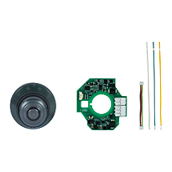
Page 7: Scope Of Supply
[7] Three-core connection cable for connecting the LED safety printed circuit board with the E-STOP pushbutton (included in Order No. 400 342) [8] Assembly aid for the terminals X1 and X2 on the LED safety printed circuit board Operating Manual PIT es Set10u-5c PCB 1004385-EN-03... -
Page 8: Marking On E-Stop Pushbutton
PIT es Set10u-5c PCB Marking on E-STOP pushbutton [1a] [1b] [1c] [1d] Legend [1a] Order number [1b] Date of manufacture mmyy [1c] Batch number [1d] Address Pilz homepage Operating Manual PIT es Set10u-5c PCB 1004385-EN-03... -
Page 9: Safety
In active state, the E-STOP device PIT es Set10u-5c PCB is lit (the actuator lights up red) and it fulfils the requirements in accordance with EN ISO 13850. In inactive state, the E-STOP pushbutton PIT es Set10u-5c PCB is not lit and it can not be detected as an emergency stop device. The E-STOP function is deactivated. -
Page 10: Safety Regulations
Are familiar with the basic regulations concerning health and safety / accident prevention, Have read and understood the information provided in the section entitled Safety Have a good knowledge of the generic and specialist standards applicable to the specific application. Operating Manual PIT es Set10u-5c PCB | 10 1004385-EN-03... -
Page 11: Warranty And Liability
The unit meets all the necessary conditions for safe operation. However, please note the following: Check the function of the pushbutton before commissioning for the first time and then at regular intervals (at least annually). Operating Manual PIT es Set10u-5c PCB | 11 1004385-EN-03... -
Page 12: Block Diagram/Terminal Configuration
The two safety circuits are opened (fully operated). The actuator is illu- minated red, the bevelled protective collar is illuminated yellow. Corresponding to the wir- ing, the yellow light is lit permanently, or it flashes. Operating Manual PIT es Set10u-5c PCB | 12 1004385-EN-03... -
Page 13: Installation
Prepare a cutout (Ø 22.3 mm) in the mounting plate. Material thickness of the mounting plate: 1 … 5 mm. The surface of the mounting plate should be smooth. Prepare another opening in the mounting plate (Ø 9 mm) for the lighting connection. Operating Manual PIT es Set10u-5c PCB | 13 1004385-EN-03... - Page 14 Fix the LED safety printed circuit board [2] with the plastic nut [3]. Note the torque setting of 1.3 ... 2.1 Nm. We recommend that you use the "PIT es wrench" installation wrench for fixing the plastic nut [3] (see Order data [ 27]). Operating Manual PIT es Set10u-5c PCB | 14 1004385-EN-03...
- Page 15 Plug the pre-installed contact blocks [5] with the bracket [4] on the neck of the E-STOP pushbutton [1] and secure it by turning it to the right. Check that the locking is correct and audible. Operating Manual PIT es Set10u-5c PCB | 15 1004385-EN-03...
-
Page 16: Wiring
E-STOP devices that have only N/C contacts. Note that when operating a conventional E-STOP device which is in the chain before the PIT es Set10u-5c PCB, the PIT es Set10u-5c PCB is not electrically supplied and therefore it is not illuminated. - Page 17 Connection X5.2 with X2.2 Yellow Connection X5.1 with X1.2 NOTICE Check the function of the emergency stop device before commissioning for the first time and then at regular intervals (at least annually). Operating Manual PIT es Set10u-5c PCB | 17 1004385-EN-03...
-
Page 18: Requirements And Connection To Evaluation Devices
PIT es Set10u-5c PCB Requirements and connection to evaluation devices For use of PIT es Set10u-5c PCB an evaluation device must be connected. Connect the PIT es Set10u-5c PCB either with a Pilz evaluation device or with an evaluation device with defined properties (see section... - Page 19 GND connection of the LED safety circuit board (see also Check wiring [ 22]). The evaluation device must switch off then. When an evaluation device does not switch off, there is a wiring error. Operating Manual PIT es Set10u-5c PCB | 19 1004385-EN-03...
- Page 20 24 V or bridge to X1.1 Yellow X1.2 Input on the evaluation device channel 1 Output on the evaluation device channel 1 X1.1 X2.1 Fig.: Connection example, flashing function is not active Operating Manual PIT es Set10u-5c PCB | 20 1004385-EN-03...
-
Page 21: Wiring Table
LED safety printed circuit board X1.2 (yellow cable) X5.2 Evaluation device input from channel 1. If a flashing func- IMx/Ix/controller input 1/ tion is required: Connect with LED safety printed circuit board X2.2 (white cable) Operating Manual PIT es Set10u-5c PCB | 21 1004385-EN-03... -
Page 22: Examples For Connection To Pilz Evaluation Devices
PIT es Set10u-5c PCB Examples for connection to Pilz evaluation devices Evaluation Internal supply voltage External supply voltage (24 V) device PNOZ s5 PIT es Set10u PCB PNOZ s5 Contact blocks LED safety printed circuit board X2.3 X2.2 X1.2 X2.1 X1.1... -
Page 23: Care And Maintenance
E-STOP pushbutton is still clearly visible, however at least once per year as part of the function test. Dust, soot and other deposits have an influence on brightness. If necessary, the E-STOP pushbutton must be cleaned or the device must be exchanged. Dimensions in mm 28.2 Operating Manual PIT es Set10u-5c PCB | 23 1004385-EN-03... -
Page 24: Technical Details
0,35 mm Amplitude Acceleration max. 50 m/s² Airgap creepage EN 60947-5-1 In accordance with the standard Overvoltage category Pollution degree 50 V Rated insulation voltage Rated impulse withstand voltage 0,5 kV Operating Manual PIT es Set10u-5c PCB | 24 1004385-EN-03... -
Page 25: Safety Characteristic Data
Please note that the Performance Level in accordance with EN 13849-1 can be reduced because of reduced fault detection when several E-STOP devices are cascaded. NOTICE Only one PIT es Set10u may be used per circuit (no cascading). Operating Manual PIT es Set10u-5c PCB | 25 1004385-EN-03... -
Page 26: Supplementary Data
From an operating height of 2000 m the max. permitted ambient temperature is reduced by 0.5 °C/100 m Operating height Permitted ambient temperature 3000 m 50 °C 4000 m 45 °C 5000 m 40 °C Operating Manual PIT es Set10u-5c PCB | 26 1004385-EN-03... -
Page 27: Order Reference
European Parliament and of the Council. The complete EC Declaration of Conformity is available on the Internet at www.pilz.com/downloads. Authorised representative: Norbert Fröhlich, Pilz GmbH & Co. KG, Felix-Wankel-Str. 2, 73760 Ostfildern, Germany Operating Manual PIT es Set10u-5c PCB...
Need help?
Do you have a question about the PIT es Set10u-5c PCB and is the answer not in the manual?
Questions and answers